SAMSUNG Proprietary-Contents may change without notice
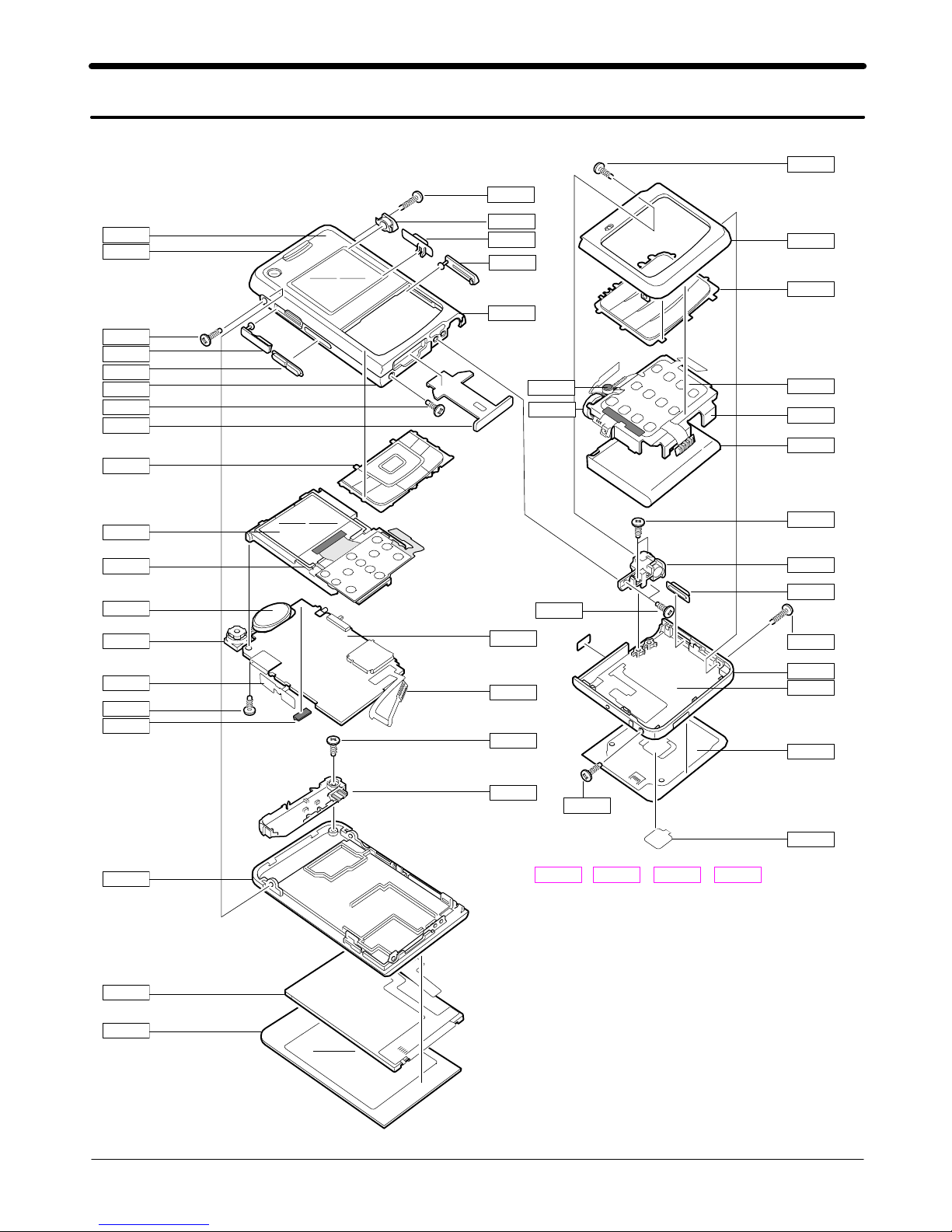
Main Electrical Parts List
2-2
This Document can not be used without Samsung's authorization
Design LOC Discription SEC CODE
QAN02 INTENNA-SGHF500 GH42-01094A
QAN05 ASSY MEC-RUBBER ANT CON GH75-09161A
QBA00 COVER BATTERY PACK-950MAH,BLK, GH43-02844A
QBA01 INNER BATTERY PACK-880MAH,BLK, GH43-02588A
QBR02 ASSY BRACKET-SUB GH98-03560A
QBR17 ASSY BRACKET-BATT GH98-02339A
QCA01 UNIT-PHONE CAMERA GH59-03593A
QCK03 PMO-KEY TOUCH OK GH72-35526A
QCR03 SCREW-MACHINE 6001-001811
QCR03 SCREW-MACHINE 6001-001811
QCR05 SCREW-MACHINE 6001-001478
QCR05 SCREW-MACHINE 6001-001478
QCR12 SCREW-MACHINE 6001-001530
QCR67 SCREW-MACHINE 6001-002083
QHI15 NDC-CASE SWING UPPER V2 GH71-07017A
QKP01 ASSY KEYPAD-MAIN(OPEN/BLK) GH98-02861A
QKP02 ASSY KEYPAD-SUB(OPEN/BLK) GH98-02860A
QKP03 MEA-TOUCH KEYPAD KIT GH97-07638A
QLC01 LCD-SGHF500 GH07-01032A
QLC02 LCD-MODULE SGHF500 GH07-00992A
QMC01 PMO-SIM COVER GH72-35542A
QME01 UNIT-TF KEY PBA GH59-03767A
QME16 UNIT-CON TO CON FPCB GH59-03792A
QMI03 ASSY RUBBER-MIC HOLDER GH98-03682A
QMO01 MOTOR DC-SPHB6400 GH31-00271A
QMP01 PBA MAIN-SGHF500 GH92-03070A
QMW01 ASSY COVER-WINDOW MAIN GH98-02870A
QRE01 ASSY COVER-REAR GH98-02868A
QRF01 PMO-COVER RF V2 GH72-35129A
QSP01 SPEAKER 3001-002109
QVK01 UNIT-SIDE KEY GH59-03762A
QWD01 ASSY COVER-WINDOW SUB GH98-02869A
QFR01 ASSY COVER-FRONT GH98-02863A
QSD01 PMO-COVER MICRO SD GH72-35529A
QHI16 ASSY COVER-SWING LOWER GH98-05068A
QCR12 SCREW-MACHINE 6001-001530
QFL01 ASSY CASE-SWING LOWER GH98-02337A
QHI01 ASSY HINGE GH98-03747A
QHI17 ASSY COVER-SWING BELT GH98-05119A
QCK01 PMO-CAMERA KEY GH72-33543A
QBR18 ASSY COVER-MAIN BELT RGH98-02864A
QCK02 PMO-HOLD KEY GH72-35531A
QBR19 ASSY COVER-MAIN BELT LGH98-02865A
QRF03 PMO-EAR JACK COVER GH72-35534A
QVO01 PMO-VOLUME KEY GH72-33544A
2-2. Cellular phone Parts list