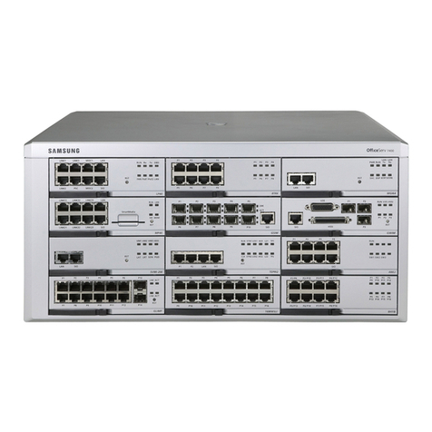
Samsung DCS 70 User manual

INSTALLATION MANUAL FOR THE
SAMSUNG DCS 70
DIGITAL COMMUNICATIONS SYSTEMS
REV 02

SAMSUNG DCS 70 10th January, 2000
INSTALLATION MANUAL
i
TABLE OF CONTENTS
CHAPTER ONE................................................................................................................... : INTRODUCTION 1-1
CHAPTER TWO........................................................................................................: SITE REQUIREMENTS 2-1
CHAPTER THREE...................................................................................: INSTALLATION OF THE DCS 70 3-1
UNPACKING AND INSPECTION.....................................................................................................................3-1
KEY SERVICE UNIT INSTALLATION............................................................................................................3-1
EXPANSION CABINET INSTALLATION .......................................................................................................3-1
PROTECTIVE EARTHING................................................................................................................................3-2
DISTRIBUTION FRAME CABLING.................................................................................................................3-3
CHAPTER FOUR...................................................................: INSTALLING CARDS IN THE DCS 70 KSU 4-1
KSU MOTHERBOARD............................................................................................................................................4-1
MEMORY (MEM) CARD .......................................................................................................................................4-1
3 TRK CARD (3TRKD70) ..................................................................................................................................4-2
6 TRK CARD (6TRKD70) ..................................................................................................................................4-2
4 TRK CARD (4TRK24).....................................................................................................................................4-2
6TRK CARD (6TRK24) .....................................................................................................................................4-2
2 SLI-C CARD.....................................................................................................................................................4-3
MISC1&2 CARDS (MISC1D70 / MISC2D70)..................................................................................................4-3
MODEM CARD (MODEMD70).........................................................................................................................4-3
8 DLI CARD (8DLID70).....................................................................................................................................4-3
8 SLI CARD (8SLID70).......................................................................................................................................4-4
6 MWSLI CARD (6MWSLID70)........................................................................................................................4-4
4BRI CARD (4BRID70)......................................................................................................................................4-4
PRI CARD (DCS CARD)......................................................................................................................................4-5
PLL BOARD (PLLD70).........................................................................................................................................4-5
VDIAL CARD (VDIAL-C) (DCS COMPACT CARD)............................................................................................4-5
BSI CARD (DECTBSI-C) (DCS COMPACT CARD) .............................................................................................4-5
E&M TIE LINE CARD (EMTIEBDD70) ...........................................................................................................4-5
LINE REVERSALS, PRS HYBRIDS & TRANSIT CONNECTIONS...............................................................4-5
METER PULSE MPD HYBRIDS.......................................................................................................................4-6
FITTING MPD & PRS HYBRIDS......................................................................................................................4-6
MODIFYING THE 3TRKD70 AND 6TRKD70 CARDS FOR USE WITH PRS HYBRIDS ............................4-7
MODIFYING THE 4TRK24 AND 6TRK24 CARDS FOR USE WITH PRS HYBRIDS..................................4-7
NOTE : AUTOGUARD ON THE 3TRK, 4TRK24 & 6TRK(D70&24) CARDS...............................................4-8
DCS 70 POWER SUPPLY & FUSING...............................................................................................................4-8
POWERING UP THE SYSTEM .........................................................................................................................4-8
POWER UP PROBLEMS....................................................................................................................................4-9
MEM CARD INDICATIONS..............................................................................................................................4-9
DEFAULT TRUNK AND STATION NUMBERING.........................................................................................4-9
CHAPTER FIVE..............................................................................................: DCS 70 - SYSTEM CABLING 5-1
SAFETY PRECAUTIONS...................................................................................................................................5-1
SYSTEM CABLING............................................................................................................................................5-1
DCS 70 DISTRIBUTION FRAME CIRCUIT ALLOCATION ..........................................................................5-2
TAIL 1 CIRCUIT ALLOCATION (KSU MOTHERBOARD TAIL).............................................................5-2
Tail 1 - First 25 Pair.........................................................................................................................................5-2
Tail 1 - Second 25 Pair.....................................................................................................................................5-3
SAMSUNG DCS 70 10th January, 2000
INSTALLATION MANUAL
ii
3 & 6 TRK CARD CONNECTIONS...................................................................................................................5-3
8 DLI CARD CONNECTIONS.....................................................................................................................................5-4
8 SLI & 6MWSLI CARD CONNECTIONS .................................................................................................................5-5
BRI ISDN CARD CONNECTIONS..............................................................................................................................5-6
DECT BSI CARD CONNECTIONS.............................................................................................................................5-7
3 & 6 TRK CARD CONNECTIONS...................................................................................................................5-8
8 DLI CARD CONNECTIONS.....................................................................................................................................5-9
8 SLI & 6MWSLI CARD CONNECTIONS ...............................................................................................................5-10
BRI ISDN CARD CONNECTIONS............................................................................................................................5-11
DECT BSI CARD CONNECTIONS.............................................................................................................5-12
CHAPTER SIX................................................. CONNECTING STATION AND OPTIONAL EQUIPMENT 6-1
CONNECTING ANCILLARY EQUIPMENT TO THE SYSTEM.....................................................................6-1
MUSIC ON HOLD / BACKGROUND MUSIC..............................................................................................6-1
EXTERNAL PAGING.....................................................................................................................................6-2
COMMON BELL............................................................................................................................................6-2
RING OVER PAGE.........................................................................................................................................6-3
STATION MESSAGE DETAIL RECORDER (SMDR).................................................................................6-3
SYSTEM PROGRAMMING FROM A PC (PCMMC)...................................................................................6-3
REMOTE PROGRAMMING..........................................................................................................................6-4
DCS 70 REMOTE PROGRAMMING MODEM CONNECTION:.....................................................................................6-4
DCS70 Programming Required: ......................................................................................................................6-4
Using an external Modem:...............................................................................................................................6-4
Set up external modem:....................................................................................................................................6-5
REMOTE PROGRAMMING USING INTERNAL OR EXTERNAL MODEM: .....................................................................6-5
CHAPTER SEVEN................................................................: CHANGING SOFTWARE ON THE DCS - 70 7-6
ACCESSING THE EPROMS..........................................................................................................................7-6
REPLACING THE EPROMS..........................................................................................................................7-6
CHAPTER EIGHT...........................................................................................................: DCS 70 PARTS LIST 8-1

SAMSUNG DCS 70 10th January, 2000
INSTALLATION MANUAL
Page1-1
Chapter One : Introduction
This manual describes the procedure to install the Key Service Unit, keysets, single line telephones
and ancillary equipment for the DCS 70 Digital Communication System.
This manual covers the hardware installation and cabling only. The system programming and
configuration is described in the DCS Installation and Maintenance Manual and in the System
Administrators manual.
The operation of the keysets and the single line telephones (SLT’s) is described in the user guides.
The Samsung DCS 70 system should only be installed by fully trained
and qualified personnel.

SAMSUNG DCS 70 10th January, 2000
INSTALLATION MANUAL
Page 2-1
Chapter Two : Site Requirements
The installation site for the Samsung DCS 70 System should meet the following requirements -
•The location for the key service unit (KSU) must provide enough space for easy installation and
have adequate lighting. The Key Service Unit measures 57cm high by 36cm wide by 13cm deep.
•Select a location that will minimize cable lengths. See the maximum cable length limits in Chapter
6.
•The equipment should not be exposed to moisture, direct sunlight, corrosive fumes, dust, constant
vibration or strong magnetic fields such as those generated by motors and copy machines.
•A single phase, correctly earthed, 240V, 10Amp, 50Hz, AC General Purpose Outlet (GPO) must
be provided within two metres of the KSU. The GPO must be easily accessible and kept clear of
obstructions. Extension cords must not be used. A dedicated, separately fused circuit should be
used to minimize the risk of other electrical equipment being connected that could adversely affect
system operation.
•Ensure that all wires and cable going to and coming from the KSU are properly routed. The cables
should not cross fluorescent lights or run parallel with AC wires.
•The equipment must be located in an environment that will remain within the Temperature range
of 0oC to 45oC and 10% to 95% Relative Humidity, non-condensing.
•Allow at least 30cm clearance on both sides and 30cm clearance on top of the KSU to ensure
proper ventilation. Refer to Figure 2.1
•Do not install the KSU in close proximity to a fire sprinkler head or other sources of water.
Meeting these requirements will help to ensure proper performance and greater life expectancy of the
system.
Immunity to Interference.
The DCS 70 System has been designed to be immune to the levels
of interference normally found within residential and commercial
premises (for example, mains dips and breaks, electro-static
discharge, overvoltages and transients, electromagnetic fields).
It is the customer’s responsibility to provide an environment for the DCS 70 system, Keysets and
cabling that does not contain excessive sources of interference that could affect the operation of the
systems.

SAMSUNG DCS 70 10th January, 2000
INSTALLATION MANUAL
Page 2-2
Figure 2-1. Wall Mounting the KSU
Min 300
mm
Min 300
mm
Min 300
mm
Min 380
mm
Max 1800 mm

SAMSUNG DCS 70 10th January, 2000
INSTALLATION MANUAL
Page 3-1
Chapter Three : Installation Of The DCS 70
UNPACKING AND INSPECTION
After unpacking the KSU, inspect the unit for signs of physical damage. KSUs with any sign
of physical damage should be returned to the supplier for replacement.
Check to see that the KSU carton includes the following items:
•DCS 70 Key Service Unit (KSU) which includes:
•Memory card
•20W Ringer
•Paper Mounting Template
•Power cable
•Wall-mount kit consisting of cable ties, four screws, spare fuses and Battery Backup cable
The EXPANSION Cabinet is provided as an add-on option. If provided, check that the
expansion cabinet carton includes the following:
•Expansion Cabinet
•Mounting screws and cable tie.
KEY SERVICE UNIT INSTALLATION
The Key Service Unit (KSU) must be wall-mounted in a vertical position.
The KSU has 4 key holes on the sides of the KSU for wall mounting. See Figure 3.1
Use the mounting template supplied to position the screw holes correctly. Insert the screws
but do not tighten.
Position the KSU on to all screws at the same time and then lower the KSU so that it is
secured in the Keyholes. Tighten all screws to complete the installation.
(see Figure 3-1).
The KSU should be mounted on a section of the wall capable of holding the weight of the
system (approximately 12 Kg fully loaded including Expansion Cabinet) and cables. For
example close to a stud or noggin.
EXPANSION CABINET INSTALLATION
The DCS 70 system is shipped from the factory equipped with the 008 motherboard, Memory
card power supply and ringer.
The expansion metal cabinet is an optional cabinet that provides 3 additional universal
expansion slots and a dedicated expansion slot for future features such as an integrated Voice
mail card, PRI card and E&M tie line card. The expansion cabinet is supplied in separate
packaging and is installed as described below.
1. The Expansion Cabinet has two mounting lugs on the left hand side of the cabinet
which fit into slots on the KSU. In addition the cabinet has 2 key holes on the right
hand side of the cabinet to complete the mounting. (see Fig 3-3)

SAMSUNG DCS 70 10th January, 2000
INSTALLATION MANUAL
Page 3-2
2. Using the mounting template supplied with the DCS 70 KSU to position the mounting
screws supplied. Insert the screws but do not tighten.
3. Switch off the power and remove the cover on the KSU
4. Remove the dummy tabs on the right side of the KSU with the appropriate tools to
allow for connections between the KSU and the Expansion Cabinet. Hole A is for the
tail cable and hole B is for the signal and power cables. (see Fig 3.2)
5. Move the Expansion cabinet to the KSU and slide the lugs on the base of the
Expansion cabinet into the slots on the side of the KSU and lower the Expansion
Cabinet. (see Fig 3.4)
NOTE : Care should be taken to ensure that the ribbon cable and other connecting cables are
not caught between the cabinets.
6. Connect the the flat ribbon cable and the top signal cable to the header marked P12 on
the KSU motherboard. (See Figure 3.5).
Connect the second cable from the header marked RING.GND on the expansion
cabinet backplane to the header marked P8 on the KSU motherboard.
Screw the single green wire to Land marked F.G. on the KSU Motherboard.
7. Insert the cable tail through the KSU and into the Expansion cabinet . Insert new
option cards and close the cabinets with the covers provided, secure the covers with the
screws on the base of the units and switch ON the power. (See Figure 3-6).
PROTECTIVE EARTHING
The protective earth connection to the DCS 70 is provided via the three core mains lead. The
earth wire in the mains cord (Green/Yellow) is connected in the factory to the earth terminal
within the system. The Earth wire is connected directly to the bottom left hand corner of the
Power Supply case
The protective earth (PE) is used for surge protection and for the electrical safety of the
system. The system must be plugged into a GPO socket that is correctly earthed. The PE
provides all system earthing requirements, a TRC is not required and should not be
connected.
WARNING
The equipment, users and service personnel must be protected against possible voltage and
current surges on exchange lines when working on the KSU. This must be done using one, or
both, of the following methods when installing or working on the system -
•Plug the mains lead into the GPO socket, ensuring that the socket is turned off.
•Isolate the exchange lines from the system. This may be done by isolating the lines at a
distribution frame.
The Power Supply has fuses in both the mains active and neutral legs, therefore caution
should be used when working on or near the power supply. Turn OFF the power supply
switch on the KSU before working on the system.

SAMSUNG DCS 70 10th January, 2000
INSTALLATION MANUAL
Page 3-3
DISTRIBUTION FRAME CABLING
Connections to the DCS 70 system are made by way of a customer provided system
distribution frame (SDF). All connections are made via the SDF except for the serial data
ports, 240VAC mains and battery back up.
The KSU and Expansion Cabinet are each connected to the SDF using 2x25 pair AMP
Champ cables and 1x25 pair AMP Champ cable respectively. The retaining screw on the
AMP Champ connectors should be used to hold the connector in place. The 25 pair cables
should be routed via the cable brackets inside the DCS 70 KSU and clamped to the cable
anchoring points using nylon cable ties.. The 25 pair cables should be routed into the KSU
and Expansion cabinet from below. (See Fig 3.6)
Label each cable to correspond with the connector numbers.

SAMSUNG DCS 70 10th January, 2000
INSTALLATION MANUAL
Page 3-4
Figure 3-1 KSU Mounting Holes
Mounting
Holes
MOH
LINK
S
L
O
T
1
S
L
O
T
2
M
I
S
C
M
E
M
2
S
L
I
S
L
O
T
3
Ringer
Power Supply
P2
P1
Mounting
Holes
PLL Card
Connectors

SAMSUNG DCS 70 10th January, 2000
INSTALLATION MANUAL
Page 3-5
Figure 3-2 Knock Outs For Expansion Cabinet
Installation

SAMSUNG DCS 70 10th January, 2000
INSTALLATION MANUAL
Page 3-6
Figure 3-3 Expansion Cabinet
S
L
O
T
3
S
L
O
T
4
S
L
O
T
5
S
L
O
T
6
D
E
D
I
C
A
T
E
D
S
L
O
T

SAMSUNG DCS 70 10th January, 2000
INSTALLATION MANUAL
Page 3-7
Figure 3-4 Expansion Cabinet Installation
S
L
O
T
3
S
L
O
T
6
D
E
D
I
C
A
T
E
D
S
L
O
T
S
L
O
T
4
S
L
O
T
5
M
I
S
C
M
E
M
2
S
L
I
S
L
O
T
3
Ringer
Power Supply
P
P
S
L
O
T
2
S
L
O
T
1

SAMSUNG DCS 70 10th January, 2000
INSTALLATION MANUAL
Page 3-8
Figure 3-5 Connection of Expansion Cabinet Cables
M
I
S
C
M
E
M
2
S
L
I
S
L
O
T
3
Ringer
Power Supply
P2
P1
S
L
O
T
2
S
L
O
T
1S
L
O
T
3
S
L
O
T
6
D
E
D
I
C
A
T
E
D
S
L
O
T
S
L
O
T
4
S
L
O
T
5

SAMSUNG DCS 70 10th January, 2000
INSTALLATION MANUAL
Page 3-9
M
I
S
C
M
E
M
2
S
L
I
S
L
O
T
3
Power Supply
P2
P1
S
L
O
T
2
S
L
O
T
1S
L
O
T
3
S
L
O
T
6
D
E
D
I
C
A
T
E
D
S
L
O
T
S
L
O
T
4
S
L
O
T
5
Battery
- +
P3

SAMSUNG DCS 70 10th January, 2000
INSTALLATION MANUAL
Page 4-1
Chapter Four : Installing Cards In The DCS 70 KSU
Unpack and inspect each card for physical damage before installation. Contact the supplier if
any damage to the card is detected. Do not attempt to install a damaged card.
WARNING. The Samsung DCS 70 system contains many
static sensitive components. To reduce the incidence of
premature equipment failure, observe the following
precautions -
•Always discharge static from yourself before handling any Printed Board Assemblies
(PBA’s) and wear an anti-static wrist strap connected to the KSU earth lug.
•Always handle boards by the edges.
•Never touch PBA tracks or connectors. Contaminants introduced by fingers can cause
corrosion and high resistance connections.
•Never touch or straighten components, especially the ceramic sub-assemblies. They
are physically delicate and finger pressure can fracture component leads (even if the
leads do not actually break).
•To protect PBAs against physical damage and damage due to static discharge, always
wrap them in an anti-static bag and replace them in the packaging provided with the
new item.
WARNING
Power must be switched OFF before any cards are
removed or installed.
KSU Motherboard
The DCS 70 motherboard provides 8 digital extension ports, each of which will support a
daughter board extension, one external MOH/BGM port (see Fig 4.1) one external page
interface, one general purpose dry contact, 3 universal expansion slots, a Memory card slot,
MISC card slot and a 2SLI slot.
Memory (MEM) Card
Insert the MEM card in the KSU slot labelled MEM (see Figure 4-1). Push firmly in the
middle of the MEM card to ensure that it is fully inserted into the backplane connector.
To prevent accidental damage to the MEM card, the connector on the backplane is positioned
to mate only with the MEM card. Other interface cards will not mate with this connector and
the MEM card will not mate with any other connector.
The MEM card has a switch labelled OFF or ON. (The switch connects/disconnects the
supercap to the MEM for backing up the RAM data).

SAMSUNG DCS 70 10th January, 2000
INSTALLATION MANUAL
Page 4-2
When the system is first turned on, the switch should be in the OFF position to erase the
RAM data. Once the system is powered up, the BACK UP switch should be switched to the
ON position.
The MEM card also contains a RUN LED. When the system is first powered on, the LED
will be steady for about ten seconds after which the LED will flash to show that the CPU is
running normally. If the LED does not start flashing after 20 seconds, power the system off
and check the installation.
3 TRK CARD (3TRKD70)
The 3TRK card provides three exchange line interfaces with Caller ID relays.The first two
ports are also equipped with PFT relays. The 3TRK card may be optionally fitted with meter
pulse or polarity reversal detect hybrids (see below). The card is supplied from the factory
with no hybrids fitted.
Insert the card into any universal card slot in the KSU or Expansion Cabinet (see Figure 4-1).
Push firmly in the middle of both card ejectors to ensure that it is fully inserted into the
backplane connector.
6 TRK CARD (6TRKD70)
The 6TRK card provides six exchange line ports, with the first two ports equipped with PFT
relays. This card does not support Caller ID. The 6TRK card may be optionally fitted with
meter pulse or polarity reversal detect hybrids (see below). The card is supplied from the
factory with no hybrids fitted.
Insert the 6 TRK card into any universal card slot in the KSU or Expansion Cabinet(see
Figure 4-1). Push firmly in the middle of both card ejectors on each card to ensure that it is
fully inserted into the backplane connector. A maximum of 3 cards can be installed.
4 TRK CARD (4TRK24)
This 4 trunk card is used in the DCS24 system. It can also be used in the DCS70 system with
Version 6 software. The 4TRK24 card provides four exchange line interfaces with Caller ID
relays. The 4TRK24 card may be optionally fitted with meter pulse or polarity reversal detect
hybrids (see below). The card is supplied from the factory with no hybrids fitted.
Insert the card into any universal card slot in the KSU or Expansion Cabinet (see Figure 4-1).
Push firmly in the middle of both card ejectors to ensure that it is fully inserted into the
backplane connector.
6 TRK CARD (6TRK24)
This 6 trunk card is used in the DCS24 system. It can also be used in the DCS70 system with
Version 6 software. The 6TRK24 card provides six exchange line interfaces with Caller ID
relays. The 6TRK24 card may be optionally fitted with meter pulse or polarity reversal detect
hybrids (see below). The card is supplied from the factory with no hybrids fitted.
Insert the card into any universal card slot in the KSU or Expansion Cabinet (see Figure 4-1).
Push firmly in the middle of both card ejectors to ensure that it is fully inserted into the
backplane connector.

SAMSUNG DCS 70 10th January, 2000
INSTALLATION MANUAL
Page 4-3
WARNING.
The 3TRK, 6TRK, 4TRK24, 6TRK24 and the 2SLI boards are
provided with overvoltage protection against voltage surges
that are typically found on telephone lines in Australia.
In lightning prone areas, additional overvoltage protection
must be fitted to the lines to prevent premature equipment
failure.
2 SLI-C CARD
The 2SLI card is an optional board that provides two single line telephone (SLT) ports.
These ports have been designed for use as Outdoor Extensions (ODX) and provide the same
overvoltage protection as the exchange line ports. These ports may also be used for internal
use. This card has no selectable options. Insert the 2 SLI card into the dedicated 2SLI slot
(see Figure 4-1). Push firmly in the middle of both card ejectors to ensure that it is fully
inserted into the backplane connector. The 2SLI-C Card is the same as that used in the DCS
Compact system.
Note: The DCS 70 only supports DTMF dialling single line telephones, fax or modems.
Decadic dialling is not supported on the DCS 70.
MISC1&2 CARDS (MISC1D70 / MISC2D70)
There are two optional MISC cards MISC 1, which provides two serial data ports, additional
DTMF receivers (4 ch.), a second external Music On Hold input, an additional external page
interface, three general purpose relays and circuitry for an alarm sensor. There are no
options to select on this card. Insert the MISC card into the appropriate slot (see Figure 4-1).
The MISC 2 card is equipped with a built in 4 channel Auto Attendant feature in addition to
the facilities on the MISC 1 card. Both MISC cards support analogue CLIP and also an
optional modem to support remote maintenance. (See Fig 4.2) and
To insert the cards push firmly in the middle of both card ejectors on each card to ensure that
it is fully inserted into the backplane connector.
NOTE: Only one MISC card can be installed in a system.
MODEM CARD (MODEMD70)
The Modem card is an optional daughter card which can be installed on the MISC 1 or MISC
2 card. Align the modem card with the 2 x14 pin male connectors on the MISC card and the
arrow on the Modem card pointed towards the front of the card, and push firmly home. (See
Fig 4.2)
8 DLI CARD (8DLID70)
The 8DLI card is an optional expansion board that provides eight digital extension lines (DLI
ports) These ports do not support daughter card extensions. There are no options to select
on this card. Insert the 8 DLI card into any universal card slot in the KSU or Expansion

SAMSUNG DCS 70 10th January, 2000
INSTALLATION MANUAL
Page 4-4
Cabinet. (see Figure 4-1). Push firmly in the middle of both card ejectors on each card to
ensure that it is fully inserted into the backplane connector.
8 SLI CARD (8SLID70)
The 8SLI card is optional expansion board that provides eight SLT interfaces for connecting
single line telephones, answering machines, faxes etc. The ports on this card are for internal
use only. This card should not be used for Outdoor Extensions (ODX) since its use as an
ODX may cause damage to the KSU.
There are no options to select on this card. Insert the 8 SLI card into any universal card slot
in the KSU or Expansion Cabinet.(see Figure 4-1). Push firmly in the middle of both card
ejectors on each card to ensure that it is fully inserted into the backplane connector.
Note: The DCS 70 only supports DTMF dialling single line telephones, fax or modems.
Decadic dialling is not supported on the DCS 70.
6 MWSLI CARD (6MWSLID70)
The 6MWSLI card is optional expansion board that supports six SLT interfaces for
connecting single line telephones and provides a message waiting signal. The ports on this
card are for internal use only. This card should not be used for Outdoor Extensions (ODX)
since its use as an ODX may cause damage to the KSU.
There are no options to select on this card. Insert the 6 MWSLI card into any universal card
slot in the KSU or Expansion Cabinet.(see Figure 4-1). Push firmly in the middle of both
card ejectors on each card to ensure that it is fully inserted into the backplane connector.
Note: The DCS 70 only supports DTMF dialling single line telephones, fax or modems.
Decadic dialling is not supported on the DCS 70.
4BRI CARD (4BRID70)
The BRI card is an optional expansion board that supports up to four BRA Trunks and BRA
extensions. The selection of BRA trunks or extensions is via MMC 423. The card also
supports optional power feed to basic rate terminals connected to BRA extensions. There are
no options to select on this card. Insert the BRI card into any slot on the universal card slot
(see Figure 4-1). Push firmly in the middle of both card ejectors on each card to ensure that
it is fully inserted into the backplane connector. A maximum of 3 cards can be installed in
the DCS70. Note that the 4BRI-C Card used in the DCS Compact cannot be used in the
DCS70.
The DCS 70 must be the only equipment connected to each Basic Rate trunk when the ISDN
is being used for Indial.
Standard installation procedures should be used for cable lengths, cable types and earthing
when connecting the ISDN lines from the SDF to the NT1.
Note: When the BRI card is installed in the system a PLL daughter board must also be
installed

SAMSUNG DCS 70 10th January, 2000
INSTALLATION MANUAL
Page 4-5
PRI CARD (DCS Card)
The PRI card contains one primary rate ISDN access. This card is the same as the DCS PRI
card without the Plastic case. This card has no selectable options. Insert the card into the
dedicated slot in the Expansion cabinet. Push firmly in the middle of both card ejectors on
each card to ensure that it is fully inserted into the backplane connector.
Note: When the PRI card is installed into the system:
1. A PLL card must also be installed
2. Universal card slot 6 must be left vacant.
PLL Board (PLLD70)
The PLL (Phase Lock Loop) card is required when a BRI or PRI card is installed in the DCS
70. The PLL is a daughter card which is installed on the KSU motherboard (See Fig. 4.1).
Align the PLL card with the 14 pin male connectors on the KSU motherboard and push
firmly on the edges of the PLL card in the middle of the 14 pin female connector on either
side of the card.
VDIAL CARD (VDIAL-C) (DCS Compact card)
The VDIAL card is an optional expansion board that is used to provide the voice dialling
feature. The card stores recorded voice patterns and performs the voice recognition function.
There are no options to select on this card. Insert the VDIAL card into any universal card slot
in the KSU or Expansion Cabinet (see Figure 4-1). Push firmly in the middle of both card
ejectors on each card to ensure that it is fully inserted into the backplane connector.
BSI CARD (DECTBSI-C) (DCS Compact Card)
The BSI card is an optional expansion card used to interface to the DECT Base Stations. The
BSI card on the DCS 70 provides connection for three DECT Base Stations. There are no
options to select on this card. Insert the BSI card into any universal card slot in the KSU or
Expansion Cabinet (see Figure 4-1). Push firmly in the middle of both card ejectors on each
card to ensure that it is fully inserted into the backplane connector. Note that only one BSI
card can be installed in the DCS70.
E&M TIE LINE CARD (EMTIEBDD70)
The E&M Tie Line card supports four 6 wire E&M ports. Insert the card into the dedicated
slot in the Expansion cabinet. Push firmly in the middle of both card ejectors on each card to
ensure that it is fully inserted into the backplane connector.
LINE REVERSALS, PRS HYBRIDS & TRANSIT CONNECTIONS
Polarity reversal (PRS) hybrids may be fitted as an option to the 3TRK, 4TRK and 6TRK
cards. The hybrids detect the polarity change at the end of a call and clear down the call.
The exchange line ports must be programmed correctly (Refer to MMC414) for the PRS
hybrids to work.
The operation of the DCS 70 with the PRS hybrid detects polarity reversals a therefore does
not depend on the exchange line being installed with the “correct” polarity ie. if L+ and L-
are reversed the PRS hybrids will continue to work correctly. (The DCS 70 system
automatically detects the polarity of the line in idle).
Table of contents
Other Samsung Telephone Accessories manuals

Samsung
Samsung SVMi-4 Guide

Samsung
Samsung DCS COMPACT II Operating and maintenance instructions

Samsung
Samsung EF-NG980 User manual

Samsung
Samsung NX-828 User manual

Samsung
Samsung Vehicle Dock User manual

Samsung
Samsung Ubigate iBG3026 User manual

Samsung
Samsung DS 5000 Series User manual

Samsung
Samsung ET-CG930 User manual

Samsung
Samsung iDCS 28D User manual

Samsung
Samsung iDCS 100 Operating and maintenance instructions