Samsung iDCS 100 Operating and maintenance instructions

Digital Communications System
General Description
Every effort has been made to eliminate errors and ambiguities in the information
contained in this guide. Any questions concerning information presented here
should be directed to SAMSUNG TELECOMMUNICATIONS AMERICA, 2700 NW
87th Avenue, Miami, FL 33172, telephone (305) 592-2900. SAMSUNG
TELECOMMUNICATIONS AMERICA disclaims all liabilities for damages arising
from the erroneous interpretation or use of information presented in this guide.
iDCS
100
HOME
PAGE
Table of
Contents

telecommunications
Publication Information
SAMSUNG TELECOMMUNICATIONS AMERICA reserves the right without prior
notice to revise information in this publication for any reason.
SAMSUNG TELECOMMUNICATIONS AMERICA also reserves the right without
prior notice to make changes in design or components of equipment as
engineering and manufacturing may warrant.
Copyright 2002
Samsung Telecommunications America
All rights reserved. No part of this manual may be reproduced in any form or by
any means—graphic, electronic or mechanical, including recording, taping,
photocopying or information retrieval systems—without express written
permission of the publisher of this material.
PRINTED IN USA 06/02
HOME
PAGE
Table of
Contents

TABLE OF CONTENTS
PART DESCRIPTION PAGE
1SYSTEM OVERVIEW
1.1 SIZE AND CONFIGURATION ............................................................ 1.2
1.2 TECHNOLOGY.................................................................................. 1.5
1.3 PROGRAMMING ................................................................................ 1.6
2HARDWARE DESCRIPTIONS
2.1 KEY SERVICE UNIT........................................................................... 2.1
2.2 EXPANSION CABINETS .................................................................... 2.1
2.3 MEM3 AND MEM4 CARDS ................................................................ 2.2
2.4 INTERFACE CARDS .......................................................................... 2.2
2.5 STATION EQUIPMENT ...................................................................... 2.6
3SPECIFICATIONS
3.1 ELECTRICAL SPECIFICATIONS ....................................................... 3.1
3.2 DIMENSIONS AND WEIGHTS .......................................................... 3.1
3.3 ENVIRONMENTAL LIMITS ................................................................. 3.2
3.4 CABLE REQUIREMENTS .................................................................. 3.2
3.5 SYSTEM TONES ............................................................................... 3.2
3.6A KEYSET KEY LED INDICATIONS...................................................... 3.4
3.6B TERMINAL STATUS LED INDICATIONS ........................................... 3.4
3.7A RESERVE POWER DURATION ESTIMATES .................................... 3.5
3.7B RESERVE POWER DURATION ESTIMATES
–WITH/WITHOUT SVMi .................................................................... 3.6
4FEATURES
4.1 SYSTEM FEATURES ......................................................................... 4.1
4.2 STATION FEATURES ...................................................................... 4.28
4.3 DISPLAY FEATURES ....................................................................... 4.36
4.4 SAMPLE SMDR PRINTOUT ............................................................. 4.44
4.5 SAMPLE SMDR PRINTOUT WITH CALLER ID................................ 4.45
4.6 SAMPLE UCD REPORT ................................................................... 4.46
4.7 CALL STATISTICS........................................................................... 4.47
4.8 AGENT STATISTICS........................................................................ 4.49
4.9 SAMPLE TRAFFIC REPORT ............................................................ 4.50
4.10 TRAFFIC REPORT OVERVIEW ....................................................... 4.51
4.11 SAMPLE ALARM REPORT ............................................................... 4.56
HOME
PAGE
Table of
Contents

5GENERAL USER INFORMATION
5.1 RADIO FREQUENCY INTERFERENCE ............................................ 5.1
5.2 FCC REQUIREMENTS ...................................................................... 5.1
5.3 TELEPHONE COMPANY INTERFACES ............................................ 5.2
5.4 SAFETY TESTS ................................................................................. 5.3
5.5 MUSIC ON HOLD WARNING ............................................................ 5.3
5.6 EQUAL ACCESS REQUIREMENTS .................................................. 5.4
HOME
PAGE
Table of
Contents

iDCS 100 GENERAL SYSTEM DIAGRAM
1.1
HOME
PAGE
Table of
Contents

PART 1. SYSTEM OVERVIEW
1.1 SIZE AND CONFIGURATION
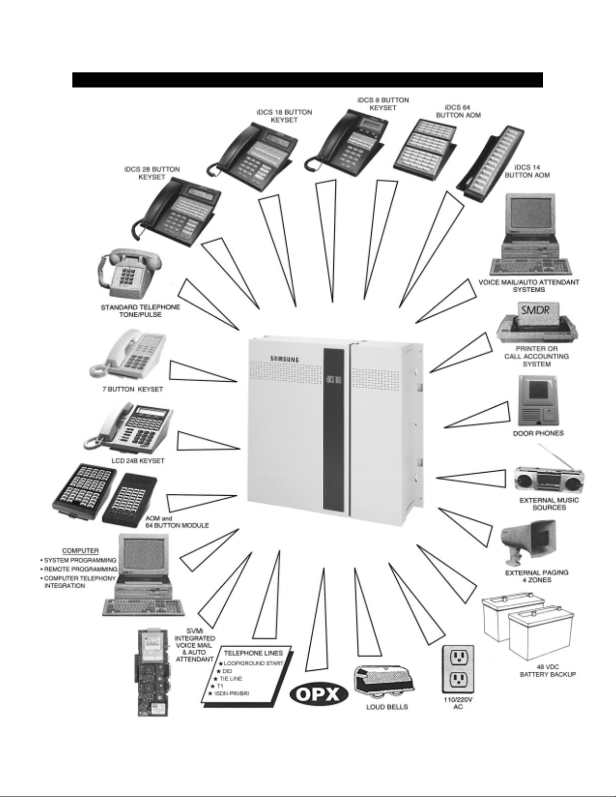
The iDCS 100 is a digital ISDN compatible telephone system designed for small busi-
nesses. It can operate with the functionality of a square key system, PABX or a combina-
tion of both (hybrid). The iDCS 100 employes the very latest DSP (Digital Signal Proces-
sor) digital technology.
The iDCS 100 offers a variety of interface cards that allow connection to the public tele-
phone network or to private networks. These are generally referred to as trunk cards. Two
types of telephones can be connected to the system. Proprietary digital phones called
“keysets”connect to digital line interface cards (DLI). Standard telephones generally called
“single line sets”connect to single line interface cards (SLI). In addition, DLI station ports
are used to connect peripheral devices such as door phones and add-on modules. Mis-
cellaneous circuits are provided to allow such optional features as external paging, mu-
sic on hold, background music, common audible devices, alarms and emergency power
failure telephones.
All keysets utilize a single PCB with surface-mounted components assuring the highest
product quality and long life. Samsung’s customary large, easy-to-read displays and LEDs
in the button design make them much easier to use. In many instances, sophisticated
features are made simple through the use of friendly display prompts or push-on/push-
off feature keys.
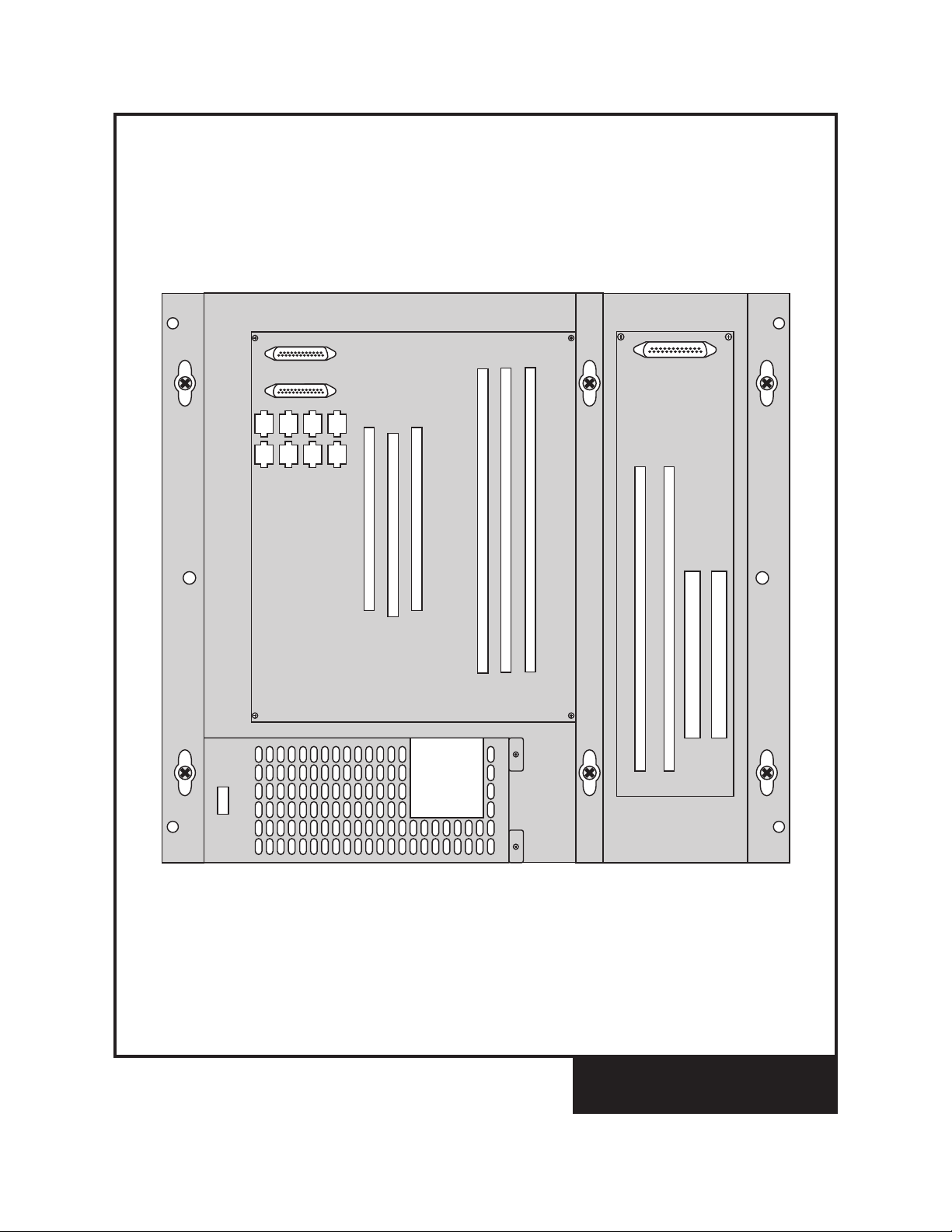
Expanding the iDCS 100 system is both economical and easy. Begin with the basic Key
Service Unit and then add an expansion cabinet as your business grows (See Figure 1–1,
Figure 1–2). The KSU has 8 keyset ports and 3 universal card slots that can be used for
stations, trunks or 2x4 combination cards. In addition, the KSU has dedicated slots for a
2SLI card and a miscellaneous function card. There is one of two expansion cabinets to
choose from (type-A or type-B). A type-A expansion cabinet adds a further 3 universal
slots and a dedicated slot for a Samsung Plug-In Voice Mail card or a T1/PRI card. A type-
B expansion cabinet adds a further 2 universal slots and two dedicated slots for a Samsung
Plug-In Voice Mail card and a T1/PRI card. The systems low density card design allows
greater flexibility when configuring a system for the right combination of lines and sta-
tions. A removable memory card makes it convenient to upgrade to future feature pack-
ages as well as providing quick and easy servicing. The maximum quantities of the vari-
ous station and trunk types can be seen in the table 1–1.
1.2
HOME
PAGE
Table of
Contents

FIGURE 1–1
KEY SERVICE UNIT AND
EXPANSION CABINET TYPE-A
UNIVERSAL SLOT 4
UNIVERSAL SLOT 5
UNIVERSAL SLOT 1
UNIVERSAL SLOT 2
UNIVERSAL SLOT 3
2SLI SLOT
MEM SLOT
MISC SLOT
SVMi-8 /T
EPRI
UNIVERSAL SLOT 6
1.3
HOME
PAGE
Table of
Contents

FIGURE 1–2
KEY SERVICE UNIT AND
EXPANSION CABINET TYPE-B
UNIVERSAL SLOT 4
UNIVERSAL SLOT 5
UNIVERSAL SLOT 1
UNIVERSAL SLOT 2
UNIVERSAL SLOT 3
2SLI SLOT
MEM SLOT
MISC SLOT
SVMi-8
TEPRI
1.4
HOME
PAGE
Table of
Contents

FIGURE 1–1
FIGURE 1–2
1.5
SEITITNAUQECIVEDMUMIXAM
EPYTECIVEDTUOHTIWUSP
MVS
HTIWUSP
MVS
)SECIVEDILD&S'TLS(SNOITATS6584
)SMIPD/SMOA/STESYEK(SECIVEDILD6584
SENOHPELETENILELGNIS2443
SENILTRATSPOOL6363
STIUCRICIRB4242
SLENNAHCIRB8484
SKNURTM&E2121
STROP8-iMVS08
STROP4-iMVS04
sknurTlatigiDIRP/1T)42(1)42(1
TABLE 1–1
CONFIGURATION NOTES
1. Only one 2 SLI card can be installed in the system.
2. Only one SMISC card can be installed in the system.
3. Up to six expansion cards can be installed in the system with Type B Expansion Cabi-
net and five slots for a Type A Expansion Cabinet.
4. Only one SVM card can be installed in the system.
5. Installing SVMi-8 reduces the maximum number of stations by 8. Installing the SVMi-4
card reduces the maximum number of stations by 4.
6. Only eight KDbs can be installed in the system and they must be installed on keysets
connected to the (8) eight 2B+D ports on the KSU motherboard.
7. Only one TE/PRI card can be installed in the system.
8, Only one ITMC card can be installed in the system.
1.2 TECHNOLOGY
System switching is accomplished by means of a custom IC “engine” that provides 128
switchable digital channels. Each of the 128 digital channels is automatically assigned to
carry voice or data as required by system operation in a PCM format. In addition to the 128
channels mentioned above , the system also utilizes Digital Signal Processors or DSPs.
Each DSP may be configured by the switching control program as a DTMF receiver or a
C.O. tone detector on a per-call basis. The engine chip contains four DSPs and four more
are added when an SMISC card is installed. This means that the system contains a total of
HOME
PAGE
Table of
Contents

1.6
eight DSP channels when fully expanded. The DSP channels are fully shared throughout
the system as a common resource.
MEMORY
The system operates using stored program control. This program is stored in EPROMs for
MEM3 or Flash Media for a MEM4 card. All specific customer data is stored in non-volatile
random access memory (NV-RAM) located on the removable MEM3 and MEM4 card. It is
protected by a super capacitor providing seven days of memory protection in the event of
loss of AC power to the system.
MICROPROCESSORS
The iDCS 100 uses distributed processing. The system’s primary processor is a 16 bit
Motorola® MC68000 operating at a clock speed of 16MHz. The secondary level of pro-
cessing is done in the keysets.
1.3 PROGRAMMING
The IDCS 100 comes with default data. This data provides for operation within seconds
after applying power. All trunks and stations are assigned according to the default num-
bering plan. This numbering plan is flexible and may be changed if so desired. The
technician customizes this default data to meet the end user’s requirements.
The system can be programmed from any display keyset without interrupting normal
system operation. There are three levels of programming: TECHNICAL, CUSTOMER and
STATION. The technician level has access to all programs and can allow the customer
access to system programs as needed. Technician and customer access are controlled
by different security passcodes.
The iDCS 100 also allows the use of a proprietary computer program called PCMMC. This
permits a technician to program the system using a personal computer. PCMMC can be
used on-site to modify the customer database or to download (save) the entire customer
database to a file. This file can then be saved as a backup and uploaded when required
to restore the database.
Through the use of modems, PCMMC can access an iDCS 100 system remotely (off-site)
to make database changes or perform uploads or downloads of the customer database
as if the technician were on-site.
HOME
PAGE
Table of
Contents

PART 2. HARDWARE DESCRIPTIONS
2.1 KEY SERVICE UNIT
The iDCS 100 (see Figure 2–1) is a metal cabinet containing the following:
!A power supply (120 VAC) with battery backup (48VDC) connection
!Processing, switching and the system operating program
!Eight 2B + D digital keyset interfaces
!One MOH/BGM input source (switch selectable between internal chimes and external
input)
!One page output
2.2 EXPANSION CABINETS
One of two optional cabinets may be used (see Figure 2–2) and they consist of a metal
case containing a backplane PCB. The first type of expansion cabinet (type-A) comes
with connectors for three expansion cards and a fourth connector for either a Samsung
Plug-In Voice Mail Card or a Digital Trunk Card (TE/PRI). The second type of expansion
cabinet (type-B) comes with connectors for two expansion cards and a third for a Samsung
Plug-In Voice Mail card and a fourth for a Digital Trunk Card (TE/PRI). The expansion
cabinet (type-A or type-B) is installed to the right of the basic KSU and connects to the KSU
motherboard via a ribbon cable and two pairs of wires.
2.1
FIGURE 2–1FIGURE 2–2
HOME
PAGE
Table of
Contents

2.3 MEM3 AND MEM4 CARD
To operate, the KSU must be equipped with an iDCS 100 MEM3 or an iDCS 100 MEM4
card to hold the system software and customer database. The software is stored in EPROM
chips for the iDCS 100 MEM3 card and in Flash Memory on an iDCS 100 MEM4 card. All
specific customer data is stored in non-volatile random access memory (NV-RAM). The
MEM3 and MEM4 cards are both protected by a super capacitor providing up to seven
days of memory protection in the event of loss of AC power to the system.
2.4 INTERFACE CARDS
2 SLI
This card is installed in a dedicated slot on the KSU motherboard. The card provides two
single line telephone interfaces equipped with OPX protection and the ability to provide
a loop disconnect signal. This is the same card used on the DCS Compact and 50si.
2 x 4 DLI
This card provides two Caller ID-compatible loop start C.O. interfaces and four 1B+D DLI
ports. KDb’s cannot be used with this card. This is the same card used on the DCS Com-
pact and 50si.
S8DLI
This card provides eight 1B+D DLI ports. KDb’s cannot be used with this card.
2 x 4 SLI
This card provides two Caller ID-compatible loop start C.O. interfaces, four SLI ports for
industry standard single line telephones and the ability to provide a loop disconnect
signal.
NOTE: This card does not provide OPX protection. This is the same card used on the
DCS Compact and 50si.
S8SLI
This card provides eight SLI ports for industry standard single line telephones and the
ability to provide a loop disconnect signal.
NOTE: This card does not provide OPX protection.
S3TRK
This card provides three Caller ID-compatible loop start C.O. interfaces with power failure
transfer on the first two ports.
2.2
HOME
PAGE
Table of
Contents

2.3
S6TRK
This card provides six Caller ID-compatible loop start C.O. interfaces.
2 E & M x 4 DLI
This card provides two two wire (TL11M) tie line interfaces and four 1B+D DLI ports. KDb’s
cannot be used with this card. This is the same card used on the DCS Compact.
S4BRI
This card provides 4 ISDN Basic Rate Interface (BRI) S/T circuits with the ability to support
two channels per circuit for a total of 8 channels. A system can have up to six of these
cards. These S/T circuits can be configured for station or trunk use. An NT1 is required for
connection to a telephone company BRI circuit. The BRI card requires that an SPLL daughter
board be installed in the KSU.
TE/PRI
When programmed as a T1 this card provides up to 24 trunk circuits in any combination of
the following:
!Loop start lines
!DID (Direct Inward Dialing)
!Ground start lines
!E & M tie lines or two way DID calling
When the card is programmed as a PRI it will provide 23 bearer channels and 1 data
channel (23B+D). This card can only be installed when Type A or Type B Expansion
Cabinet are installed.
SPLL Daughter Board
This daughter board is required to provide clocking for the S4BRI card and/or a TEPRI
card. If an S4BRI or TEPRI card is to be installed an SPLL daughter board must also be
installed.
NOTE: Only one SPLL daughter board is required per system however many S4BRI cards
are installed.
SMISC1
This card provides a second MOH/BGM input, three general purpose relays, an alarm
sensor, two serial I/O ports, caller ID decoding circuits, and four DSP circuits. That may be
required for DID/ANI/DNIS. It is recommended that this card be used in situations requir-
ing heavy single line telephone use.
SMISC2
This card is similar to the SMISC1 but with the addition of four ports of auto attendant.
HOME
PAGE
Table of
Contents

2.4
FKDBD
If your iDCS keyset is connected to a Digital Line Interface (DLI) port that supports 2B+D
operation (your installing company can determine this) you may install a daughter mod-
ule that provides a Digital Line Interface (DLI) port for connection of a digital station device
such as a keyset or 64 button module.
KDb-DLI
This board, if installed in a digital keyset connected to one of the eight DLI ports on the
motherboard, will provide a second DLI port for the connection of a digital station device.
FKDBS
If your iDCS keyset is connected to a Digital Line Interface (DLI) port that supports 2B+D
operation (your installing company can determine this) you may install a daughter mod-
ule that provides a Single Line Interface (SLI) port for connection of a standard telephone
device such as a cordless phone.
KDb-SLI
This board, if installed in a digital keyset connected to one of the eight DLI ports on the
motherboard, will provide an SLI port for the connection of a standard telephone device.
NOTE: The SLI port on a KDb-SLI cannot provide disconnect signal or OPX protection.
FKDBF
The standard speakerphone mode of operation for a iDCS keyset is “half duplex”. This
means that you cannot transmit and receive speech at the same time. Adding a FKDBF to
your keyset will convert the speakerphone into full duplex mode enhancing its operation.
NOTE: The circuitry on a FKDBF does not provide a disconnect signal or have the over-
voltage protection necessary for OPX operation.
SMODEM Daughter Board
The SMODEM Daughter Board plugs on the SMISC card and provides a 14.4 Kbps mo-
dem for remote programming.
SVMi-8
The SVMi-8 is a self contained plug in Voice Mail and Auto Attendant card for the DCS,
DCS 50si, iDCS 500, and iDCS 100. It is designed to meet the demands of the sophisti-
cated voice mail user without sacrificing simplicity.
The SVMi-8 may act as an Auto Attendant system only, a Voice Mail System only or both.
Out of the box the SVMi-8 can handle 4 calls simultaneously. It can be easily upgraded to
handle up tp 8 calls simultaneously.
HOME
PAGE
Table of
Contents

No external line or power connections are necessary, these are accomplished directly
through the phone system.
At the time of this writing the memory capacity is about 100 hours, although as time goes
on, improvements in technology will allow for changes in storage time.
The SVMi-8’s modular design allows it to be expanded to add voice ports as needed.
Only one SVMi-8 card can be installed in a system, do not use other voice mail system in
combination with SVMi-8.
SVMi-4
The SVMi-4 is a self contained plug in Voice Mail and Auto Attendant card for the DCS
Compact, DCS 50si, and iDCS 100. It is designed to meet the demands of the sophisti-
cated voice mail user without sacrificing simplicity.
The SVMi-4 may act as an Auto Attendant system only, a Voice Mail System only or both.
Out of the box the SVMi-4 can handle 2 calls simultaneously. It can be easily upgraded to
handle up tp 4 calls simultaneously.
No external line or power connections are necessary, these are accomplished directly
through the phone system.
At the time of this writing the memory capacity is about 5 hours, although as time goes on,
improvements in technology will allow for changes in storage time.
Note: An upgrade key is required for the SVMi-4 card to work.
2.5
HOME
PAGE
Table of
Contents

2.6
2.5 STATION EQUIPMENT
iDCS 28D KEYSET
(See Figure 2–7)
!32 character display (2 x 16) with three
associated soft keys and a scroll key
!28 programmable keys with tri-colored
lights
!Four fixed function keys
!Terminal Status Indicator
!Built-in speakerphone
!Eight selectable ring tones
!UP/DOWN buttons for digital control of
speaker, handset and ringer volumes
!Desk- or wall-mounted
!Available in dark gray or light gray
iDCS 18D KEYSET
(See Figure 2–8)
!32 character display (2 x 16) with three
associated soft keys and a scroll key
!18 programmable keys with tri-colored
lights
!Four fixed function keys
!Terminal Status Indicator
!Built-in speakerphone
!Eight selectable ring tones
!UP/DOWN buttons for digital control of
speaker, handset and ringer volumes
!Desk- or wall-mounted
!Available in dark gray or light gray
FIGURE 2–7
FIGURE 2–8
HOME
PAGE
Table of
Contents

2.7
iDCS 8D KEYSET
(see Figure 2–9)
!32 character display (2 x 16) with three
associated soft keys and a scroll key
!8 programmable keys with tri-colored
lights
!Four fixed function keys
!Terminal Status Indicator
!Built-in speakerphone
!Eight selectable ring tones
!UP/DOWN buttons for digital control of
speaker, handset and ringer volumes
!Desk- or wall-mounted
!Available in dark gray or light gray
iDCS 64B AOM
(See Figure 2–10)
!64 programmable keys with red lights
!A maximum of 2 can be assigned to any
keyset to provide additional program-
mable keys
!A maximum of 4 per iDCS 100 System
!Available in dark gray or light gray
FIGURE 2–9
FIGURE 2–10
HOME
PAGE
Table of
Contents

2.8
DCS LCD 24B Keyset (See Figure 2–11)
!Built-in speakerphone
!24 programmable keys (16 with tri-col-
ored LEDs)
!Four fixed function keys
!32 character display (2 x 16) with three
associated soft keys and a scroll key
!UP/DOWN buttons for digital control of
speaker, handset and ringer volumes
!Eight selectable ring tones
!Desk- or wall-mounted
!Available in almond or charcoal
DCS LCD 12B Keyset (see Figure 2–12)
!32 character display (2 x 16) with three
associated soft keys and a scroll key
!Built-in speakerphone
!12 programmable keys (six with tri-col-
ored LEDs)
!Four fixed function keys
!UP/DOWN buttons for digital control of
speaker, handset and ringer volumes
!Eight selectable ring tones
!Desk- or wall-mounted
!Available in almond or charcoal
!Also available in a Non-Display version
DCS 7 Button Model Keyset
(see Figure 2–13)
!7 programmable keys
!Three fixed function keys
!UP/DOWN buttons for digital control of
speaker and ringer volumes
!Eight selectable ring tones
!Desk or wall mounted
!Available in almond or charcoal
FIGURE 2–13
FIGURE 2–11
FIGURE 2–12
HOME
PAGE
Table of
Contents

2.9
Single Line Telephone (See Figure 2–14)
!Four fixed function keys: hold, flash, new
call, and monitor.
!Data Port: selectable to share station ex-
tension or utilize a separate extension
!On hook dialing
!Message Waiting/Ring Indicator
!Desk or wall mounted
!Ring volume control
!Four available ring tones.
!Available in almond and black
Note: This single line telephone set is FCC approved for direct connection to the public telephone network.
FCC # A3LKOR-24627-TE-T REN 0.9B. UL LISTED 19X9 FILE # ETI 8093
32 Button Add-On Module (AOM)
(see Figure 2–15)
!32 programmable keys
!Two fixed function keys
!UP/DOWN buttons for digital control of
speaker and ringer volumes
!Available in almond or charcoal
!One or two can be assigned to any keyset to
provide executive off-hook voice announce
and additional programmable keys (see Fig-
ure 2–16)
!Can operate as a stand-alone handsfree tele-
phone unit
FIGURE 2–14
FIGURE 2–15
FIGURE 2–16
HOME
PAGE
Table of
Contents

2.10
64 Button Module (See Figure 2–17)
!64 programmable keys
!Available in almond and charcoal
!A maximum of 2 can be assigned
to any keyset to provide
additional programmable keys
!A maximum of 4 per iDCS 100
System
FIGURE 2–17
Door Phone Interface Module (DPIM) and Door Phone (see Figures 2–18 and 2–19)
!The DPIM adapts any DLI circuit for use with the door phone unit
!Commonly used to request entry through locked doors (interior or exterior) or as a room
monitoring box
!Provides contact control to be used with customer-provided electric door lock
!Door phone is wall-mounted
!Door phone is weather resistant
FIGURE 2–18
FIGURE 2–19
HOME
PAGE
Table of
Contents
Other manuals for iDCS 100
2
Table of contents
Other Samsung Telephone Accessories manuals

Samsung
Samsung Vehicle Dock User manual

Samsung
Samsung DCS Compact User manual

Samsung
Samsung OfficeServ 7400 Operating and maintenance instructions

Samsung
Samsung DS 5000 Series User manual

Samsung
Samsung NX-828 User manual

Samsung
Samsung HS3000 User manual

Samsung
Samsung DCS COMPACT II Operating and maintenance instructions

Samsung
Samsung DCS 70 User manual

Samsung
Samsung ET-CG930 User manual

Samsung
Samsung SVMi-4 Guide