2
IMPORTANT SAFETY INSTRUCTIONS – SAVE THESE INSTRUCTIONS – PLEASE READ ENTIRE MANUAL PRIOR TO USE
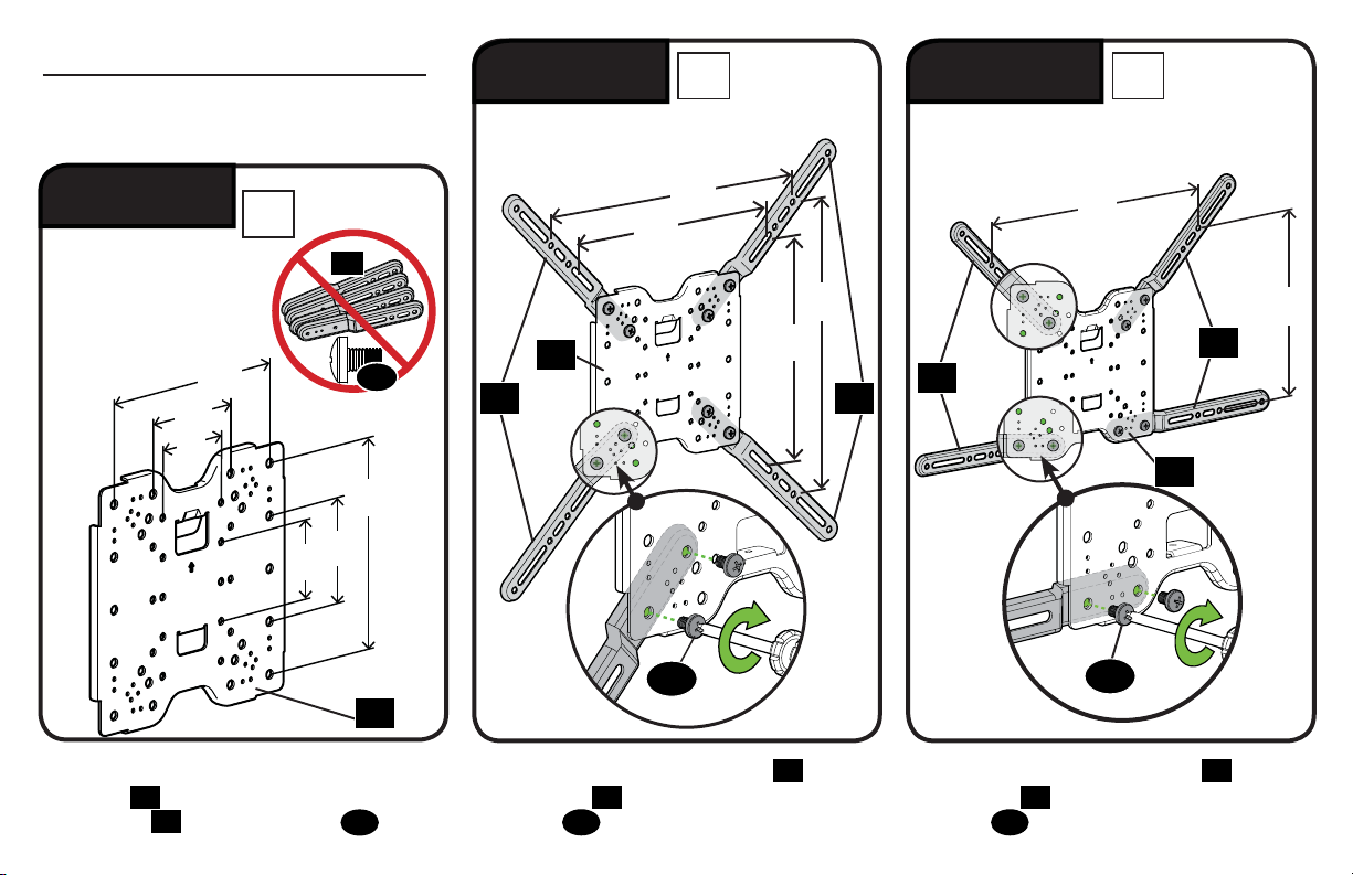
Before getting started, let’s make sure this mount is perfect for you!
No
—
Perfect!
Yes
—
This mount is NOT compatible. Visit vuepoint.sanus.com or call
1-888-333-9952 to find a compatible mount.
Please read through these instructions completely to be sure you’re comfortable with this easy install process.
Also check your TV owner’s manual to see if there are any special requirements for mounting your TV.
If you do not understand these instructions or have doubts about the safety of the installation, assembly or use
of this product, contact Customer Service at 1-888-333-9952.
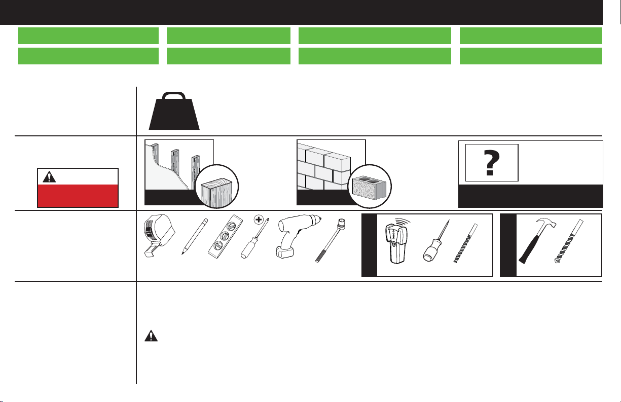
Do you have
all the tools
needed?
1
2
3
4
What is your
wall made of?
100 lbs.
(45.4 kg)
Ready to begin?
Does your TV
(including accessories)
weigh more than
100 lbs. (45.4 kg)?
CAUTION:
DO NOT install
into drywall alone
Unsure?
Drywall with
wood studs? Solid concrete or
concrete block?
Call Customer Service:
1-888-333-9952
Perfect! Perfect!
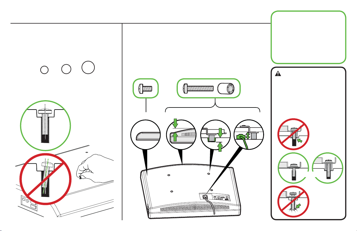
CAUTION: Avoid potential personal injuries and property damage!
●This product is designed for use in wood stud, solid concrete, and concrete block walls - DO NOT install into drywall alone
●The wall must be capable of supporting five times the weight of the TV and mount combined
●Do not use this product for any purpose not explicitly specified by manufacturer
●Manufacturer is not responsible for damage or injury caused by incorrect assembly or use
Wood Stud Install
Concrete Install
Awl
Pencil Level Stud Finder
Screwdriver
Tape
Measure
7/32 in.
(5.5 mm)
Wood
Drill Bit
Electric
Drill Hammer
1/2 in.
(13 mm)
Socket
Wrench Drill Bit
3/8 in.
(10 mm)
Concrete
Texto en español, página 22
Svensk text sida 46
Texte français page 28
日本語は52ページ
Deutscher Text Seiten 34
中文文字说明请参见第 58 页
Nederlandse tekst op pagina 40
Русский текст: стр. 64