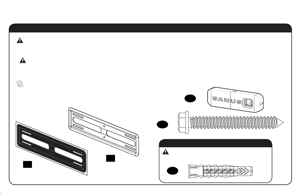
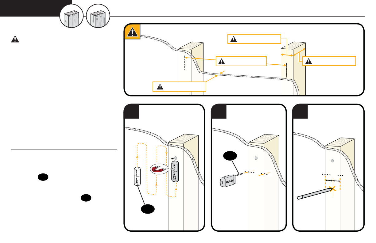
Sanus BML1 User manual

THANK YOU FOR CHOOSING SANUS
THE #1 TV MOUNT BRAND IN THE US.
Scan for easy
install video
BML
1
Instruction Manual

WARNING:This product contains a magnet. If an implanted medical device such as a pacemaker or implantable cardioverter defibrillator (ICD) is in use, magnetic fields may aect the operation of
those devices, resulting in serious injury or death. If you have an implanted medical device, keep at least 13 cm (5in.) between your device and the magnet. Please consult with your physician or medical
professional prior to using this product.
SANUS
MAGNETIC STUD FINDER
Designed to find your studs and make life easier– included in hardware kit.
TWO SIMPLE STEPS
TO FINDING YOUR STUDS:
Holding it vertically, lightly move the SANUS
Magnetic Stud Finder up and down while
sliding across your wall. The magnet within
will be attracted to the screws in the stud.
Once the magnet has landed on a screw,
place a pencil mark on the wall
directly below the magnet.
You can verify this is a stud by moving the
Magnetic Stud Finder up or down to find
a second or third screw within the wall.
Pull apart the SANUS Magnetic Stud Finder to
expose the probing pin within. Starting about
1/2inch away from the first pencil mark insert
the probing pin into the wall every 1/8inch until
it inserts completely into the wall. Once that
happens, you know you've found one edge of
your stud. Repeat this process till you have
found the stud edges and center of the stud.
Step 1 Step 2
magnet
locates screws in drywall
to show exactly where
your studs are
probing pin
helps find the edges of
your stud within the wall
level
attaches to your wall plate
for hands free leveling

3
BML1
Lo haremos sin estrés
Si tiene preguntas mientras realiza la instalación, llámenos.
1-800-359-5520 (Reino Unido: 0800-056-2853) Estamos listos para ayudarlo.
We’ll Make It Stress-Free
If you have any questions along the way, just give us a call.
1-800-359-5520 (UK: 0800-056-2853) We’re ready to help!

4
IMPORTANT SAFETY INSTRUCTIONS – SAVE THESE INSTRUCTIONS – PLEASE READ ENTIRE MANUAL PRIOR TO USE
Please read through these instructions completely to be sure you’re comfortable with this easy install process.
Also check your TV owner’s manual to see if there are any special requirements for mounting your TV.
If you do not understand these instructions or have doubts about the safety of the installation, assembly or use
of this product, contact Customer Service at 1-800-359-5520 (UK: 0800-056-2853).
Do you have
all the tools
needed?
Before getting started, let’s make sure this mount is perfect for you!
1
2
3
4
What is your
wall made of?
Drywall
with wood
studs?
Solid concrete
or concrete
block?
75 lb
(34 kg)
CAUTION: Avoid potential personal injuries and property damage!
●This product includes directions and hardware for use with wood stud, solid concrete and concrete block walls –
DO NOT install into drywall alone. For information on how to use this product with steel stud walls contact Customer
Service and ask about the steel stud mounting kit.
●The wall must be capable of supporting five times the weight of the TV and mount combined.
●Do not use this product for any purpose not explicitly specified by manufacturer.
●Manufacturer is not responsible for damage or injury caused by incorrect assembly or use.
Perfect! Perfect!
Ready to
begin?
CAUTION:
DO NOT install
into drywall alone
Does your TV weigh
(including accessories)
more than 75 lbs.
(34 kg)?
Para Español ver página 28
No
—
Perfect!
Yes
—
This mount is NOT compatible. Visit MountFinder.Sanus.com or call
1-800-359-5520 (UK: 0800-056-2853) to find a compatible mount.
Wood Stud Install
Steel Stud Install
Concrete Install
Pencil Screwdriver
Tape
Measure
7/32 in.
(5.5 mm)
Wood
1/2 in.
(13 mm)
Steel
Drill Bit Drill Bit
Electric Drill Hammer
1/2 in.
(13 mm)
Socket
Wrench Drill Bit
3/8 in.
(10 mm)
Concrete
Drywall
with steel
studs?
Unsure?
Call Customer Service: 1-800-359-5520 (UK: 0800-056-2853)
Steel stud kit required [NOT INCLUDED]

5
M4 x 20mm M5 x 20mm
M6 x 25mm M8 x 25mm M8x30 mm
TV Screws
TV Washers Spacers
TV Brackets
03 x4
05 x4 06 x4
09 x4
07 x4 08 x4
02 x4
04 x4
01 x2
NOTE: Not all hardware included will be used.
WARNING: This product contains small items that could be a choking hazard if swallowed.
Before starting assembly, verify all parts are included and undamaged. If any parts are missing or damaged, do not return the damaged
item to your dealer; contact Customer Service. Never use damaged parts!
Parts and Hardware for STEP 1
9.5 mm
STEP 1 Attach Brackets to TV

6
1.1 Select TV Screws
Hand thread screws into the threaded inserts on the back of your TV
to determine which screw diameter (M4, M5, M6, or M8) to use.
1.2 Spacers
M4 M6 M8M5
If your TV included inset spacers or wall mount adapters,
see Troubleshooting on PAGE 26.
CAUTION: Verify adequate thread engagement of the
screw/washer/spacer combination on your TV.
Too short will not hold the TV and too long will damage the TV.
Too Short Correct Too Long
Mount the spacers 09 above the
TV bracket, for flat back panels
(AND the TV closer to the wall).
Mount the spacers 09 under the
TV bracket to create extra space
needed for irregular shape TV backs
or large cables.
Spacers and screws are supplied to install your TV bracket.
Determine your preference for spacer configuration when
attaching your TV bracket.
Round Back CablesInset HolesFlat Back
TV Bracket
TV Bracket
09
09
ab

7
1.3 Attach TV Brackets
Center the TV brackets 01 over your TV hole pattern as shown. Be sure to use the same holes and that the brackets are level.
NOTE: Loosen the adjustment screws Aon TV brackets 01 to extend the mounting holes over your TV hole pattern.
Install using the spacer, TV screw and washer combination you selected for your TV.
IMPORTANT: Tighten the adjustment screws Aon TV brackets 01 when finished.
CAUTION: Avoid potential personal injuries and property damage! DO NOT use a power screwdriver for this step.
Tighten screws only until TV Bracket is secured in place. DO NOT overtighten M4 screws 02 .
01
Loosen
Tighten
A
Standard
configurations are
shown. For special
applications, or if
you are uncertain
about your hardware
selection, contact
Customer Service at
1-800-359-5520
.
01
09
aSpacer, screw and washer
07 08
02 03 04 05 06
09
bSpacer, screw and washer
07 08
02 03 04 05 06
IMPORTANT:
For ease of access,
straps should
be level with the
bottom of the TV.

8
For wood stud (Single Stud) installations,
follow STEP 2B on PAGE 13
For wood stud (Double Stud) installations,
follow STEP 2A on PAGE 10
For concrete installations,
follow STEP 2C on PAGE 16
For steel stud installations,
follow STEP 2D on PAGE 18
STEP 2 Attach Wall Plate to Wall

9
Parts and Hardware for STEP 2
NOTE: Not all hardware included will be used.
WARNING: This product contains small items that could be a choking hazard if swallowed.
Before starting assembly, verify all parts are included and undamaged. If any parts are missing or damaged, do not return the damaged
item to your dealer; contact Customer Service. Never use damaged parts!
5⁄16 in. x 2 3⁄4 in.
Sanus Magnetic Stud Finder*
13 x4
10 x1 11 x1
12 x1
14 x4
Wall Plate
Wall Plate
Template
Lag Bolt
Concrete Anchor
*WARNING:This product contains a magnet. If an implanted medical device such as a pacemaker or implantable cardioverter defibrillator
(ICD) is in use, magnetic fields may aect the operation of those devices, resulting in serious injury or death. If you have an implanted medical
device, keep at least 13 cm (5 in.) between your device and the magnet. Please consult with your physician or medical professional prior to
using this product.
For concrete installations ONLY
CAUTION: Do not use in drywall or wood
UX10 x 60R

10
CAUTION: Avoid potential
personal injuries and property damage!
●Drywall covering the wall must not
exceed 5/8 in. (16 mm)
●Minimum wood stud size:
common 2 x 4 in. (51 x 102 mm)
nominal 1½ x 3½ in. (38 x 89 mm)
●Minimum horizontal space between
fasteners: 16 in. (406 mm)
●Stud centers must be verified – not all
walls have conventional 16 in. (406 mm)
or 24 in. (610 mm) stud spacing
1. Locate a nail/screw in the studs
using the Sanus magnetic stud
finder 12 provided.
2. Find the edges of the studs using the
probe of the stud finder 12 .
3. Mark the centers of the studs with
a pencil.
1 2 3
12
12
Max. 5/8 in. (16 mm)
Min. 16 in. (406 mm) Min. 3 1/2 in. (89 mm)
Min. 1 1/2 in. (38 mm)
STEP 2A Wood Stud Option (Double Stud Install)

11
4. Place the wall plate template 10 at your desired height and position the slotted holes over your stud center lines. Level the wall plate
template 10 and tape in place.
IMPORTANT: Be sure you mark and drill into the center of the stud.
5. Drill the four pilot holes using a 7/32 in. (5.5 mm) diameter drill bit.
IMPORTANT: Pilot holes must be drilled to a depth of 3 in. (75 mm).
1010
12
4 5 3 in. (75 mm)
7/32 in.
(5.5 mm)

12
13
6. Remove the wall plate template 10 .
7. Install the wall plate 11 using four lag bolts 13 . Firmly tighten all four lag bolts 13 until they are pulled flush against the wall plate 11 .
NOTE: Hold the wall plate 11 in place when tightening the first lag bolt 13 to keep the plate from shifting out of place.
CAUTION: Avoid potential personal injury or property damage! All four lag bolts 13 MUST BE firmly tightened to prevent unwanted
movement of the wall plate 11 .Ensure the wall plate is securely fastened to the wall before continuing on to the next step.
Go to STEP 3 on PAGE 22.
10 11
67

13
Max. 5/8 in. (16 mm)
Min. 1 1/2 in. (38 mm)
Min. 3 1/2 in. (89 mm)
1 2 3
12
12
CAUTION: Avoid potential
personal injuries and property damage!
●Drywall covering the wall must not
exceed 5/8 in. (16 mm)
●Minimum wood stud size:
common 2 x 4 in. (51 x 102 mm)
nominal 1½ x 3½ in. (38 x 89 mm)
●Minimum horizontal space between
fasteners: 16 in. (406 mm)
●Stud center must be verified
1. Locate a nail/screw in the stud
using the Sanus magnetic stud
finder 12 provided.
2. Find the edges of the stud using the
probe of the stud finder 12 .
3. Mark the center of the stud with
a pencil.
STEP 2B Wood Stud Option (Single Stud Install)

14
4. Place the wall plate template 10 at your desired height and position the MIDDLE HOLES over your stud center lines. Level the wall plate
template 10 and tape in place.
CAUTION: Avoid potential personal injury or property damage! You MUST install using the center holes in the stud as shown
IMPORTANT: Be sure you mark and drill into the center of the stud.
5. Drill the middle two pilot holes (into the stud) using a 7/32 in. (5.5 mm) diameter drill bit.
IMPORTANT: Pilot holes must be drilled to a depth of 3 in. (75 mm).
10 10
12
4 5 3 in. (75 mm)
7/32 in.
(5.5 mm)

15
6. Remove the wall plate template 10 .
7. Install the middle two lag bolts 13 (into the stud), and firmly tighten until they are pulled flush against the wall plate 11 .
CAUTION: Avoid potential personal injury or property damage! Both lag bolts 13 MUST BE firmly tightened to prevent unwanted
movement of the wall plate 11 . Ensure the wall plate is securely fastened to the wall before continuing on to the next step.
CAUTION: Avoid potential personal injury or property damage! The middle two lag bolts MUST be installed into a wood stud – this
product was not designed to be used in drywall alone.
Go to STEP 3 on PAGE 22.
1310 11
6 7

16
CAUTION: Avoid potential personal injuries and property damage!
●Mount the wall plate 11 directly onto the concrete surface
●Minimum solid concrete thickness: 8 in. (203 mm)
●Minimum concrete block size: 8 x 8x 16 in. (203 x 203 x 406 mm)
●Minimum horizontal space between fasteners: 16 in. (406 mm)
1. Position the wall plate template 10 on the wall at your desired height. Level the wall plate template and mark the hole locations.
2. Drill four pilot holes using a 3/8 in. (10 mm) diameter drill bit.
IMPORTANT: Pilot holes must be drilled to a depth of 3 in. (75 mm). Never drill into the mortar between blocks.
10
10
12
1 2
3/8 in.
(10 mm)
3 in. (75 mm)
Min.
16 in.
(406 mm)
STEP 2C Solid Concrete or Concrete Block Option

17
13
3. Remove the wall plate template 10 and insert four anchors 14 .
CAUTION: Be sure the anchors 14 are seated flush with the concrete surface.
4. Install the wall plate 11 using four lag bolts 13 . Firmly tighten all four lag bolts 13 until they are pulled flush against the wall plate 11 .
NOTE: Hold the wall plate 11 in place when tightening the first lag bolt 13 to keep the plate from shifting out of place.
CAUTION: Avoid potential personal injury or property damage! All four lag bolts 13 MUST BE firmly tightened to prevent unwanted
movement of the wall plate 11 .Ensure the wall plate is securely fastened to the wall before continuing on to the next step.
Go to STEP 3 on PAGE 22.
10
11
14
36

18
Steel Stud Anchor Kit [NOT INCLUDED]
1/4-20 x 1.75
1/4-20 Snap Toggle BB
.734 x .312 x .065 in.
Min. 16 in.
(406 mm)
CAUTION: Avoid potential personal
injuries and property damage!
●Studs must be at least 2x4 / 25 ga.
●If back side of wall is unfinished, drywall
must be installed to a minimum of one stud
left and right of the stud(s) being used to
install the mount.
●Drywall must be a minimum of 1/2 in. (13 mm)
thick on each side of the studs, and a
minimum clearance of 1 7/8 in. (48 mm)
behind the wall is required.
●This product must be centered on the studs.
●Stud type and structural strength
must conform to the North American
Specification for the Design of Cold-Formed
Steel Structural Members
[362 S 125 18, C-Shape, S - Stud Section].
●Drywall must be secured to studs with
screws 12 in. (304.8 mm) on center.
STEP 2D Steel Stud Option (Double and Single Stud Install)
S1 x4
S2 x4
S3 x4
Screw
Washer
Anchor
Contact Customer Service at
1-800-359-5520 to have this
additional hardware shipped
directly to you.
1 2 3
13
13
1. Locate a nail/screw in the stud using the Sanus magnetic stud finder 13 provided.
2. Find the edges of the stud using the probe of the stud finder 13 .
3. Mark the center of the stud with a pencil.

19
4. Place wall plate template 11 at your desired height and position over your stud center line(s). Level wall plate template 11 and tape in place.
CAUTION: Avoid potential personal injury or property damage! SINGLE STUD installs MUST use the center holes in the stud as shown.
NOTE: For assistance in determining wall plate location, see HeightFinder at sanus.com.
IMPORTANT: Be sure you mark and drill into the center of the stud.
5. Drill the four pilot holes using a 1/2 in. (13 mm) diameter drill bit in the locations illustrated for double stud or single stud installs.
IMPORTANT: Pilot holes must be drilled to a depth of 1 in. (25 mm).
4
STUD
STUD
STUD
STUD
STUD
STUD
DRYWALL
DRYWALL
5
1 in. (25 mm)
1/2 in.
(13 mm)
12 12
12 12
DOUBLE STUD DOUBLE STUD
SINGLE STUD SINGLE STUD

20
6
8
7
9
6. Insert the four anchors S1 *into the drilled holes (DOUBLE STUD installs = four in studs. SINGLE STUD installs = two in studs / two in dryway).
7. Pull to rotate the anchor S1 *inside the wall.
8. Hold the end of the anchor S1 *, while sliding the cap Pagainst the drywall.
9. Snap off the ends of the anchor S1 *to lock in place.
CAUTION: Be sure the cap Pis seated against the drywall surface and the ends of the anchor do not extend beyond the cap P- cut if neccessary.
S1 S1
S1 S1
PP
Table of contents
Other Sanus TV Mount manuals

Sanus
Sanus LL11 User manual

Sanus
Sanus CILT3 User manual

Sanus
Sanus Classic MLT15 User manual

Sanus
Sanus DLL1 User manual

Sanus
Sanus VDLT16 User manual

Sanus
Sanus VisionMount MF215 User manual

Sanus
Sanus SLF428-B2 User manual

Sanus
Sanus Premium VLT5B1 User manual

Sanus
Sanus HMF115 User manual

Sanus
Sanus VSL4 User manual

Sanus
Sanus BLL2 User manual

Sanus
Sanus VMFL1 User manual

Sanus
Sanus SLT4 User manual

Sanus
Sanus Vuepoint F58c2 User manual

Sanus
Sanus Classic MLT13 User manual

Sanus
Sanus SLF5 User manual

Sanus
Sanus Classic MLL12 User manual

Sanus
Sanus 65PFL5604/F7 User manual

Sanus
Sanus 6901-170131 User manual

Sanus
Sanus VLF613 User manual