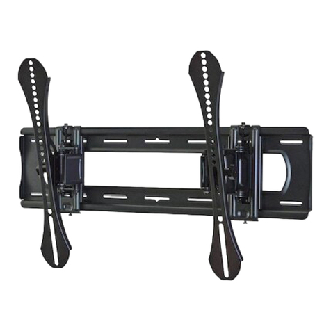
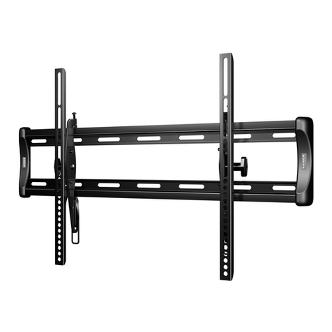
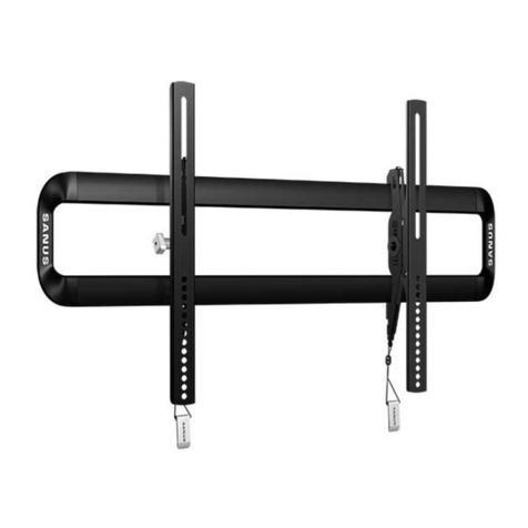
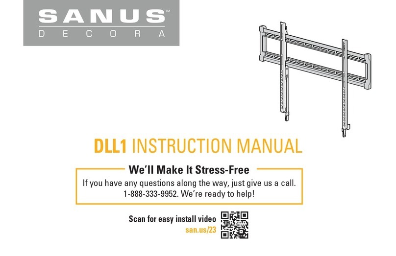
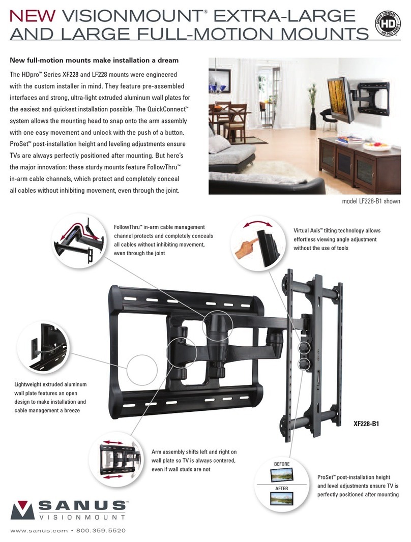
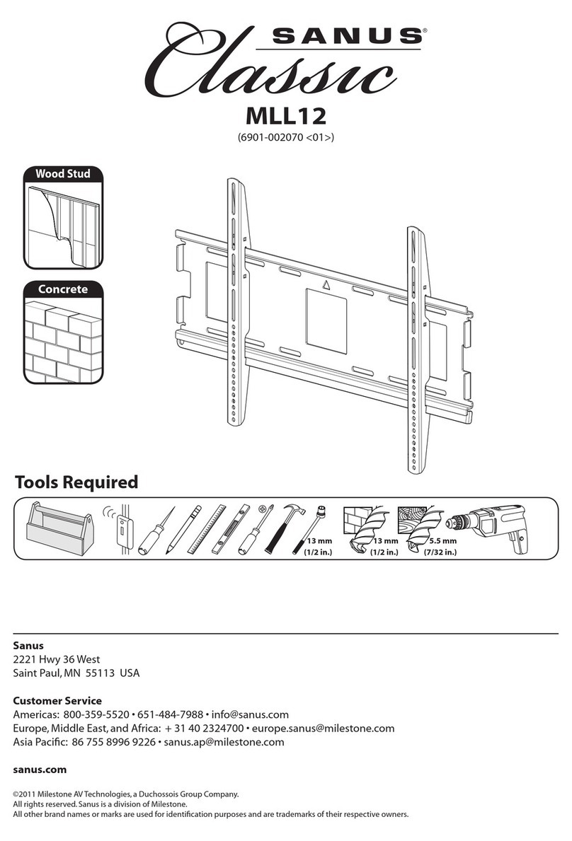
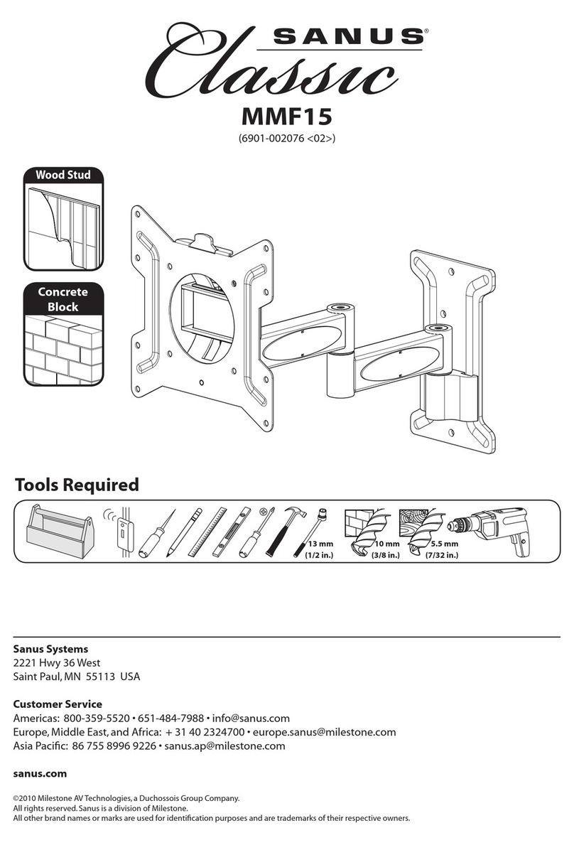
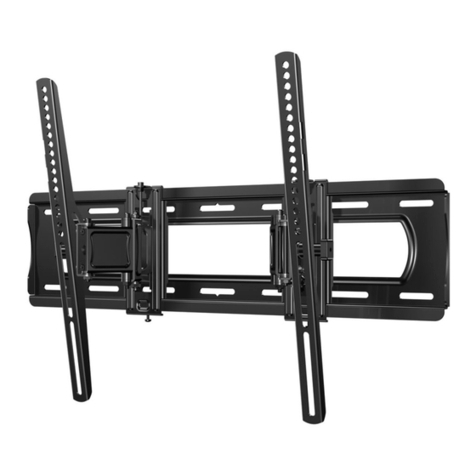
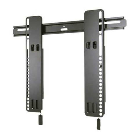
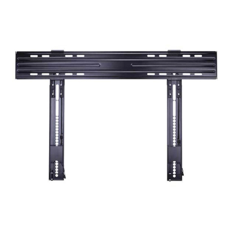
Sanus CILT3 User manual

CILT
3
TILTING
TV WALL MOUNT
INSTRUCTION MANUAL
We’ll Make It Stress-Free
If you have any questions along the way, just give us a call.
1-800-359-5520. We’re ready to help!
NOTE TO
INSTALLER:
Please leave this
manual with the
homeowner
Texto en español, página 12

2
IMPORTANT SAFETY INSTRUCTIONS
PLEASE READ ENTIRE MANUAL PRIOR TO USE – SAVE THESE INSTRUCTIONS
Please read through these instructions completely to be sure you’re comfortable with this easy install process.
Check your TV owner’s manual to see if there are any special requirements for mounting your TV.
If you do not understand these instructions or have doubts about the safety of the installation, assembly or use of this product,
contact Customer Service.
CAUTION: Avoid potential personal injuries and property damage!
●This product is designed ONLY to be installed into wood studs, solid concrete or concrete block.
—DO NOT INSTALL INTO DRYWALL ALONE — DRYWALL ALONE WILL NOT HOLD THE WEIGHT OF YOUR TV.
●This product is designed for INDOOR USE ONLY.
●The wall must be capable of supporting five times the weight of the TV and mount combined.
●Do not use this product for any purpose not explicitly specified by manufacturer.
●Manufacturer is not responsible for damage or injury caused by incorrect assembly or use.
TV Weight Limit
(including accessories)
DO NOT EXCEED
If your TV, plus accessories, weighs MORE
than indicated, this mount is NOT compatible.
Visit SANUS.com or call customer service to
find a compatible mount.
Call Customer Service
Tools
Needed
Wall
Construction
ONLY install on
these acceptable
wall types.
Unsure
125 lbs.
(56.6 kg)
Drywall alone
will NOT hold
the weight of
your TV.
wood studs Solid concrete or
concrete block
ACCEPTABLE ACCEPTABLE
CAUTION:
DO NOT install
in drywall alone
Wood Stud
Install
Concrete
Install
Pencil Level
Stud
Finder
ScrewdriverTape
Measure
7/32 in.
(5.5 mm)
Wood
Drill Bit
Electric
Drill
Hammer
1/2 in.
(13 mm)
Socket
Wrench
Drill Bit
3/8 in.
(10 mm)
Concrete
Legrand AV Inc. and its aliated corporations and subsidiaries (collectively, “Legrand”), intend to make this manual accurate and complete. However, Legrand makes no claim that the information contained herein covers all details,
conditions, or variations. Nor does it provide for every possible contingency in connection with the installation or use of this product. The information contained in this document is subject to change without notice or obligation of any kind.
Legrand makes no representation of warranty, expressed or implied, regarding the information contained herein. Legrand assumes no responsibility for accuracy, completeness or suciency of the information contained in this document.
©2020 Legrand AV Inc. All rights reserved. Sanus is a division of Legrand. SANUS and the SANUS logo are registered trademarks.
3
DIMENSIONS in. [mm]
7.87in
200mm
MIN
29.53in
750mm
MAX
15.75in
400mm
MAX
3.94in
100mm
MIN
2.00in
50.8mm
29.28in
743.8mm
3.01in
76.4mm
4.00in
101.6mm
16.00in
406.4mm
24.00in
609.6mm
30.51in
775mm
17.25in
438.1mm
3.31in
84mm
2deg
ROLL
0.92in
23.5mm
TV INTERFACE
WALL PLATE
TOP VIEW - TV MOUNTED
TOP VIEW
FULLY ASSEMBLED MOUNT
10deg
TILT
SIDE VIEW

4
M3
Fischer UX10 x 60R
For concrete installations ONLY
5⁄16 in. x 2 ¾ in.
5/16 in.
Parts and Hardware for STEP 2 Tool for Adjustments
06
(qty. 1)
07
(qty. 3)
09
(qty. 3) 08
(qty. 3)
10
(qty. 1)
Lag Bolt
Wall Plate
Washer
Concrete Anchor
Hex Key
PARTS AND HARDWARE
WARNING: This product contains small items that could be a choking hazard if swallowed. Before starting assembly, verify all parts are included
and undamaged. If any parts are missing or damaged, do not return the damaged item to your dealer; contact Customer Service. Never use damaged parts!
NOTE: Not all hardware included will be used.
M8 x 30 mm
M8 x 25mm
M6 x 12mm M6 x 20mm
M8 x 40mm
M8 x 45mm
M8 x 50mm
2.5mm
22mm
M6 x 35mm
M8 x 35mm
M8 x 20mm
M8 x 16mm
Parts and Hardware for STEP 1
TV Screws (qty. 4 each) [Only one size fits your TV] Washer
(qty. 4 each)
Spacers
[If necessary]
(qty. 4 each)
03
02
01
M6/M8 M6/M8
M6
M8
TV Brackets
04
(qty. 1) 05
(qty. 1)

5
NOTE:
Use any TV
supplied spacer
UNDER the
mount hardware.
CAUTION: Verify adequate thread engagement with your
screw/washer/spacer combination AND the TV brackets.
TOO SHORT will not hold the TV and TOO LONG will damage the TV.
Too Short Correct Too Long
ATTACH TV BRACKET TO TV
STEP 1
• Flat Back TV
[TV brackets lay flat
on your TV]
NO SPACER
SPACER NEEDED
• Flat Back TV with Extra Space Needed
[for deep inset holes or cable interference]
• Rounded or Irregular Back TV
[TV brackets NOT resting flat on your TV]
A B
03 03
02 02
01 01
01
02
04
05
NO SPACER
A
01
02
SPACER NEEDED
B
03
02
01
NOTE: Combine spacers
if needed.

6
STEP 2A ATTACH WALL PLATE
Wood Stud Installation
Skip to STEP 3 on PAGE 8.
CAUTION: Avoid potential personal injury or property damage!
●Drywall covering the wall must not exceed 5/8 in. (16 mm)
●Minimum wood stud size: nominal 2 x 4 in. (51 x 102 mm) actual 1½ x 3½ in. (38 x 89 mm)
●Minimum horizontal space between fasteners: 16 in. (40 cm)
●Stud centers must be verified
CAUTION: Avoid potential personal injury or property damage! Tighten lag bolts 07 ONLY until the washers 08 are pulled firmly against
the wall plate 06 .Ensure the wall plate is SECURELY fastened to the wall before continuing on to the next step.
08
06
07
2¾in. (70 mm)
7/32 in. (5.5 mm)
07 08
2X

7
STEP 2B ATTACH WALL PLATE
Solid Concrete or Concrete
Block Installation
●Mount the wall plate 06 directly onto the concrete surface
●Minimum solid concrete thickness: 8 in. (20.3 cm).
●Minimum concrete block size: 8 x 8 x 16 in. (20.3 x 20.3 x 40.6 cm)
●Minimum horizontal space between fasteners: 8 in. (20 cm)
CAUTION: Avoid potential personal injury or property damage!
CAUTION: Avoid potential personal injury or property damage! Tighten lag bolts 07 ONLY until the washers 08 are pulled firmly
against the wall plate 06 .Ensure the wall plate is SECURELY fastened to the wall before continuing on to the next step.
08
09
06
07
3 in. (75 mm)
07 08 09 3/8 in. (10 mm)
3X 3X

8
ATTACH TV TO WALL PLATE
STEP 3
HEAVY!
You may need
assistance
with this step.
3
21
05
04
06

9
MANAGE CABLES
1. Pull down and hold both release cords Rwhile
gently pulling the bottom of the TV away from the
wall until the kick stands Kfall into place.
CAUTION: To prevent breaking the locking
latch: always pull and hold the release cords R
down while pulling the TV away from the wall.
2. Temporarily rest the TV on the kick stands K
while connecting the cables to the TV.
CAUTION: TV is not secured to the wall
when it is in the kick stand Kposition.
Assistance is recommended for this step.
3. Lift the kick stands Kup while holding the TV.
4. Gently rest the TV back until the brackets click
and lock the TV in place.
1 2 34
R
K
KK
R

10
ADJUSTMENTS
LEVEL
TILT
To level your TV, turn the
level adjustment screw L
on the top of either bracket
using hex key 10 to raise
or lower that respective
side of the TV.
Raise
Lower
10
Loosen
Tighten
Your TV should adjust easily
when moved, then stay in place.
If your TV is too loose or too
tight, adjust the tension knobs
Tusing hex key 10 .
NOTE: Once your TV is
in place, tighten the tension
knobs Tto prevent unwanted
movement.
10
T
L

11
ADJUSTMENTS
HEAVY! You may need assistance with this step.
REMOVING THE TV
SIDE-TO-SIDE
Slide the TV left or right along
the wall plate 06 to reposition.
06
To remove your TV from the wall plate 06 :
1. Pull down and hold both release cords
Rwhile gently pulling the bottom of
the TV away from the wall until the kick
stands Kfall into place.
CAUTION: To prevent breaking the
locking latch: always pull and hold the
release cords Rdown while pulling
the TV away from the wall.
2. Rest the TV on the kick stands Kwhile
disconnecting the cables from your TV.
3. Lift TV up and off the wall plate to
remove.
To reattach your TV: Follow the procedures
in STEP 3 on PAGE 8.
1 2 3
K
R

12
Español
INSTRUCCIONES DE SEGURIDAD IMPORTANTES
LEA TODO EL MANUAL ANTES DE UTILIZAR ESTE PRODUCTO
Y CONSERVE ESTAS INSTRUCCIONES DE SEGURIDAD IMPORTANTES
Llame al Servicio de Atención al Cliente
La construcción
de su pared
SOLAMENTE instalar
en estos tipos
aceptables de la pared.
Instalación en panels de
yeso solo NO soportará
el peso de su TV.
¿No está seguro?
Montantes de madera Hormigón macizo o
bloque de hormigón
ACEPTABLE ACEPTABLE
PRECAUCIÓN:
NO
instalar en
panel de
yeso solo
56,6 kg
(125 lbs.)
Lea atentamente estas instrucciones en su totalidad para asegurarse de que está familiarizado con el sencillo proceso de instalación.
Consulte igualmente el manual de su televisor para conocer si existen requisitos especiales para el montaje de su aparato.
Si no entiende las instrucciones o si tiene dudas acerca de la seguridad de la instalación, el montaje o el uso del producto, póngase en contacto
con el Servicio de Atención al Cliente o llame a nuestro servicio técnico.
PRECAUCIÓN: Evite posibles lesiones personales y daños materiales.
●Este producto se ha diseñado para su uso en montantes de madera, hormigón macizo y paredes de bloques de hormigón:
NO lo instale en paredes únicamente de yeso
●Este producto está diseñado SOLO PARA USO EN INTERIORES.
●La pared debe ser capaz de soportar hasta cinco veces el peso combinado del televisor y la montura
●No utilice este producto para ningún otro propósito que no sea el explícitamente especificado por el fabricante
●El fabricante no se responsabiliza de ningún daño o lesión resultante del montaje incorrecto o el uso indebido
Peso máximo
(incluidos los accesorios)
NO EXCEDAS
Si su TV (incluidos los accesorios) pesa MÁS, esta
montura NO es compatible.
Visite sanus.com o llame al Cliente o llame a nuestro
servicio técnico para encontrar una montura compatible.
Lápiz Nivel
Localizador
de montantes
Destornillador
Cinta
métrica
Broca para
madera
de 5,5 mm
(7/32 pulg.)
Taladro
eléctrico
Martillo
Llave de
tubo de
13 mm
(1/2 pulg.)
Broca para
hormigón
de 10 mm
(3/8 pulg.)
Instalación en montantes
de madera
Instalación en
hormigón
herramientas
necesarias

13
Fijar el soporte del televisor al televisorPASO 1
PRECAUCIÓN: Compruebe el enrosque adecuado de la combinación tornillo/arandela/espaciador y los soportes del televisor.
Si el tornillo es DEMASIADO CORTO, no sostendrá el televisor. Si es DEMASIADO LARGO, el televisor se dañará.
Español
PÁGINA 5
Fijar la placa mural a la pared
PASO 2A Instalación en pared con montantes de madera
PÁGINA 6
Vaya al PASO 3 en la PÁGINA 8.
Dimensiones PÁGINA 3
Piezas y accesorios suministrados
NOTA: No todos los accesorios incluidos deberán utilizarse.
ADVERTENCIA: Este producto contiene piezas pequeñas que, si fuesen tragadas, podrían producir asfixia.
Antes de iniciar el ensamblaje, compruebe que todas las piezas estén incluidas y en buenas condiciones. Si faltan piezas o alguna está dañada,
no devuelva el artículo al distribuidor; póngase en contacto con el servicio de atención al cliente. Nunca utilice piezas deterioradas.
PÁGINA 4
PRECAUCIÓN: Evite lesiones personales y daños materiales.
●El yeso que recubre la pared no debe exceder los 16 mm (5/8'')
●Tamaño mínimo del montante de madera: nominal 51 mm x 102 mm (2'' x 4'') actual 38 mm x 89 mm (1 ½'' x 3 ½'')
●Espacio horizontal mínimo entre los elementos de sujeción: 40 cm (16'')
●Debe comprobar los montantes centrales
• TV con parte posterior plana [los soportes del televisor se apoyan planos sobre su TV]
SIN ESPACIADOR
ESPACIADOR NECESARIO
• TV con parte posterior plana que necesita espacio extra [para agujeros profundos o interferencia de cables]
• TV con parte posterior redondeada o irregular [los soportes de televisor NO se apoyan completamente planos en su TV]
A
B
NOTA: Use el separador proporcionado con el televisor
PRECAUCIÓN: Evite posibles lesiones físicas y daños materiales.
Apriete los tornillos 07 SOLO hasta que las arandelas 08 queden firmemente sujetas contra la placa de pared 06 . Asegúrese de que la
placa de pared esté bien fijada a la pared antes de continuar con el paso siguiente.

14
Español
¡ELEMENTO PESADO! Es posible que necesite ayuda en este paso.
Fijar el televisor en la placa muralPASO 3
Organizar los cables
PÁGINA 8
PÁGINA 9
Fijar la placa mural a la pared
PASO 2B Instalación en paredes de hormigón sólido
o en bloques de hormigón
PRECAUCIÓN: Evite posibles lesiones físicas y daños materiales.
Apriete los tornillos 07 SOLO hasta que las arandelas 08 queden firmemente sujetas contra la placa de pared 06 . Asegúrese de que la
placa de pared esté bien fijada a la pared antes de continuar con el paso siguiente.
PÁGINA 7
PRECAUCIÓN: Evite lesiones personales y daños materiales.
●Instale la placa mural 06 directamente sobre la superficie de hormigón
●Espesor mínimo del hormigón: 203 mm (8'')
●Tamaño mínimo del bloque de cemento: 203 x 203 x 406 mm (8'' x 8'' x 16'')
●Espacio horizontal mínimo entre los elementos de sujeción: 30 cm (12'')
1. Jale hacia abajo y sostenga ambos cordones de desenganche Rmientras tira con cuidado de la parte inferior del televisor
para separarlo de la pared hasta que los pies de apoyo Kse ubiquen en su lugar.
PRECAUCIÓN: Para que el pasador de seguridad no se rompa, siempre jale y sostenga los cordones de desenganche R
mientras retira el televisor de la pared.
2. Apoye temporalmente el televisor sobre los pies de apoyo Kmientras instala los cables en el televisor.
PRECAUCIÓN: El televisor no está fijo en la pared cuando se encuentra en la posición de los pies de apoyo K. Para este
paso, se recomienda que procure asistencia.
3. Levante los pies de apoyo Kmientras sostiene el televisor.
4. Con cuidado, apoye el dorso del televisor hasta que las placas de sujeción emitan un chasquido y fijen al televisor en su lugar.

15
Español
Ajustes
NIVEL
INCLINACIÓN
DESPLAZAMIENTO LATERAL DEL TELEVISOR
RETIRAR EL TELEVISOR ¡ELEMENTO PESADO! Es posible que necesite ayuda en este paso.
¡ELEMENTO PESADO! Es posible que necesite ayuda en este paso.
PÁGINAS 10-11
Para nivelar el televisor, gire el tornillo de ajuste de nivel Lque se encuentra en la parte superior de cualquiera de las
placas de sujeción usando la llave hexagonal 10 para subir o bajar el lado correspondiente del televisor.
Para retirar el televisor en la placa mural 06 :
1. Jale hacia abajo y sostenga ambos cordones de desenganche Rmientras tira con cuidado de la parte inferior del
televisor para separarlo de la pared hasta que los pies de apoyo Kse ubiquen en su lugar.
PRECAUCIÓN: Para que el pasador de seguridad no se rompa, siempre jale y sostenga los cordones de
desenganche Rmientras retira el televisor de la pared.
2. Apoye el televisor sobre los pies de apoyo Kmientras desconecte todos los cables en el televisor.
3. Tire de la parte inferior del televisor desde la pared lo suficiente como para inclinar el televisor hacia arriba y fuera de la placa mural 06 .
Para volver a colocar el televisor, siga el procedimiento del PASO 3 en la PÁGINA 8.
El televisor debe acomodarse fácilmente al moverlo, y luego quedar en su lugar. Si el televisor está demasiado suelto o
demasiado ajustado, ajuste las perillas de tensión Tusando la llave hexagonal 10 .
NOTA: Una vez que el televisor esté en su lugar, ajuste las perillas de tensión Tpara evitar un movimiento indeseado.
Deslice el televisor a la derecha o a la izquierda a lo largo de la placa mural 06 para reposicionarlo.

REGISTER YOUR PRODUCT
SANUS • 6436 City W est Parkway • Eden Prairie, MN 55344 USA
©Legrand AV, Inc
IT’S TIME TO SHOW OFF
Register your new mount to
make the most of your SANUS
warranty.
Visit SANUS.com to register
now– it takes 25 seconds!
When you share your handiwork
with your friends, tag
#sanusspaces
for a chance to be
featured on SANUS.com
@sanussystems SanusSystems pinterest.com/SANUS SanusSystems
6901-602480 00
Table of contents
Languages:
Other Sanus TV Mount manuals

Sanus
Sanus VisionMount LT25 User manual

Sanus
Sanus BML1 User manual

Sanus
Sanus Classic MLL12 User manual

Sanus
Sanus New VisionMount VXF220-B1 User manual

Sanus
Sanus 65PFL5604/F7 User manual

Sanus
Sanus SLT4-B2 User manual

Sanus
Sanus SLT3-B8 User manual

Sanus
Sanus VMFL1 User manual

Sanus
Sanus VisionMount VMPl50A User manual

Sanus
Sanus SA405 User manual

Sanus
Sanus New VisionMount VST15-B1 User manual

Sanus
Sanus HMF115 User manual

Sanus
Sanus 6901-170131 User manual

Sanus
Sanus VXT7-B2 User manual

Sanus
Sanus VMF322 User manual

Sanus
Sanus SASP1 User manual

Sanus
Sanus VisionMount MF215 User manual

Sanus
Sanus HLF112 User manual

Sanus
Sanus VMD2 User manual

Sanus
Sanus VLT7-B3 User manual