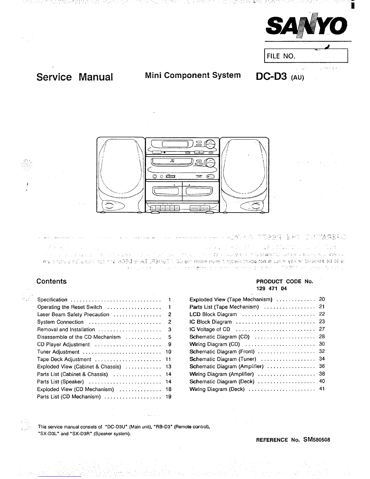
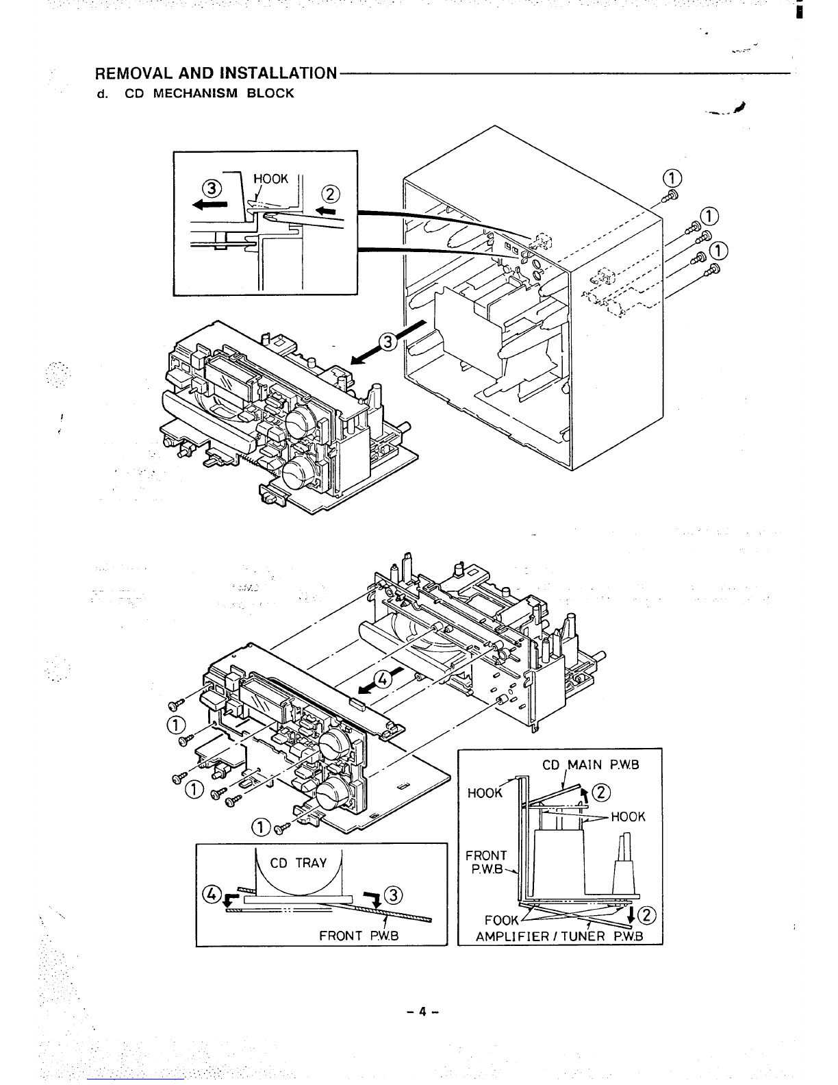
....”
TUNER ADJUSTMENTS TAPE DECK ADJUSTMENTS
●Use aplastic screw driver for ad,ustmen;s. .Speaker impedanCe :8Ohm
●Standard Output :500mW ●FM MODE switc.h :STEREO
a. PREPARATIONS FOR ADJUSTMENTS
●Measuring instruments, tools.
(1) Test tape MTT-t t4M (10 kHz) (4)
TCW-211 (1,500 Hz) (Optional)
MTT-111 (3,000 Hz) (5)
AC-224 (NORMAL) (6)
(2) Oscilloscope: (Atleast 10MHz, dual channel) (7)
(3) Oigital voltmeter (lnputimpedancel ML20r more) (8)
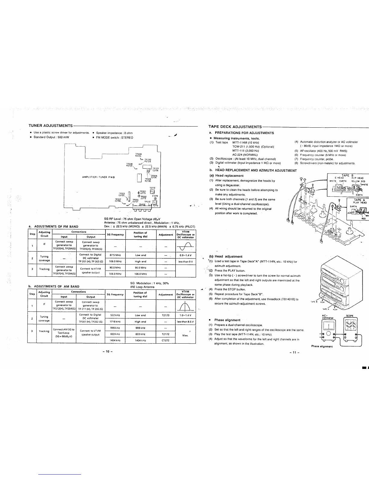
b. H;ADREPLACEMENTAND AZIMUTH ADJUSTMENT
(a) Head replacement
Automatic distortion analyzer or AC voltmeter
( - 80dB, input impedance 1ML7 or more)
AF-oscillator (400 Hz,500mV RMS)
Frequency counter (5 MHz or more)
Frequency counter, probe.
Screwdrivers (non-metalic) for adjustments.
L~TP209
R2124
rl ~~
AMPLIFIER/TuNER PWB TP206
C2134
7P205
R2130
12173
(1)
(2)
(3)
(4)
(b)
“(!)
-1.2)
(?3)
After replacement, demagnetize the heads by
using adegausser.
Be sure to clean the heads before attempting to
make any adjustments.
Besureboth channels(l and2)are the same
level (Using adual-channel oscilloscope).
All wiring should be returned to the origkal
position after work is completed.
1
1P203 ,: L&:, ❑
c2103 1’ CT272
TP207 ‘It! ~2% ‘2’72
C2156, %, #’, ~,o;’’r,~,
r-f IUud
SG RF Level :75 ohm Open Voltage dB~V
Anlenha: 750hmunbalanced direct, MocJulation:l kHz.
a. ADJUSTMENTS OF FM BAND Dev. :~22.5 kHz (MONO) ~22.5 kHz(MAlN) ~6.75 kHz(PlLOT)
x
VTVM
Oscilloscopeor
DC voltmeter
Adjusting
I
Connections
Step Position of
Circuit I
56 Frequency
Input Adjustment
output tuning dial
Connect swwp
IF Connect swwp
1generatorto generatorto — —
TP203(H), TP204(G) TP205(H). TP206(G) “
Connect to Digital
Tuning 87.s MHz Low end —
2—DC voltmeter
coverage TP 201 (H), TP 202 (G) 108.0 MHz High end —
Head adjustment
4
0.9-1.4V .
Iessthan 9VLoad atesttape in Tape Deck”A” (MTT-114N,etc.:l OkHz)for
azimuth adjustment.
Press the PLAY button.
Use aflat-tip ( - ) screwdriver to turn the screw for normal azimuth
adjustment so that the left and right outputs are maxlmtzed at the
same phase during playback.
Press the STOP butfon.
Repeat procedure for Tape Deck” B”.
After completion of the adjustment, use thread lock (TB 1401 B) to
secure the azimuth-adjustment screws.
1
Connect swwp
3Trackjng Connect to VTVM 90.0 MHz 90.0 MHz —
generator to
TP207(H), TP204(G) speaker outgut 106.0 MHz 106.0 MHz .-
SG Modulation :1kHz, 30%
IRE LooD Antenna
]. ADJUSTMENTS OF AM BAND
Step
1
2
3
—
Position of VTVM
SG Frequency Adjustment Oscilloscope or
tuning dial DC voltmeter
a‘(4)
(5)
(6)
.,
●
(1)
(2)
(3)
(4)
Adjusting Connections
Circuit Input output
IConnectswwp IConnect swwp
IF generator to aeneratorto —I I —h
ITP212(H).TPZ04(G)I TP ~1 (H),TP 206(G)
522 kHz Low end T2 t73 1.O-1.4V
1710kHz High end Iessthan 8.5 V
Vol Inwter
~b] [E] II
,hase&
0
Phase alignment
Prepare adual-channel oscilloscope.
Set so that the left and right ranges of the oscilloscope are the same.
Play the test tape (MTT-114N, etc.: 10 kH.z).
Adjust so that the waveforms for the left and right channels are in
alignment, as shown in the illustration.
Connect AM SG to
Track, ng Connect to VTVM
Test Loop
(SG =80dBpV) speaker output
-1o- -11-