Sartorius TopMix TM01-X User manual

98648-011-50
Installation Instructions
Sartorius
TopMix
Model TM01-X
Electronic Paint-mixing Weighing System

2
General View of the Equipment
1 Terminal/display and control unit (TM01-X
2 LC-display (VGA
3 QWERTY keypad
4 Mouse
5 Connector for equipotential bonding
conductor
6 Scale connection (e.g., PMA
7 Ex-link cable connection
Cable: YCC01-0038M20; length: 20 m
Connects the TopMix system to the
Ex-link box
8 VGA monitor connection
Cable: YCC01-0037M20; length: 20 m
Connects the TopMix system to the
Ex-link box
9 Bore holes (3 + for attaching the terminal
retainer to the wall
10 Connector for the power cord;
power supply: 90 to 264 VAC
11 Connector for monitor (VGA test monitor,
800x600 pixels outside the hazardous area
12 Connector for the VGA video cable
(YCC01-0039M3; length: 3 m . Connects the
Ex-link box to a standard PC outside the
hazardous area
13 USB port
14 Connector for equipotential bonding
conductor
15 Connector for the VGA cable
(YCC01-0037M20; length: 20 m . Connects
the TopMix system to the Ex-link box
16 Connector for the Ex-link cable
(YCC01-0038M20; length: 20 m . Connects
the TopMix system to the Ex-link box
17 Bore holes (2 + on mounting
bracket (wall installation device
18 Ex-link box (YCO09-Z
18
17
16
15
14
13
12
11
10
1
2
3
4
5
6
7
8
9

3
Contents Intended Use
The Sartorius TopMix paint-mixing weigh-
ing system consists of the operator termi-
nal/control panel (TM01-X, monitor and
keypad for installation in a hazardous area
and the Ex-link box (YCO09-Z for installa-
tion outside the hazardous area. These
components are connected using two
special cables which are included with the
equipment supplied (cable length: 20 m .
The TM01-X is approved for use within
Zone 1 hazardous areas. An explosion-
protected, intrinsically safe weighing
instrument must be connected to the
TM01-X unit.
A VGA video cable and USB cable are used
to connect a computer located outside the
hazardous area to the Ex-link box
(YCO09-Z .
The weighing instrument connected to the
TM01-X can be controlled through user
software installed on the computer.
Process data can be viewed on the VGA
monitor of the TM01-X at any time during
the mixing process. An additional VGA test
monitor (800x600 pixels can be connected
to the Ex-link box (YCO09-Z outside the
hazardous area.
Note:
Read the installation and operating
instructions carefully before connecting
the TopMix and putting it into operation.
2 General View of the Equipment
3 Intended Use
4 Warnings and Safety Precautions
6 Getting Started
9 Installing the TopMix System
14 Care and Maintenance
17 Specifications
17 Accessories
18 Declaration of Conformity
The followin symbols are used in
these instructions:
§indicates required steps
$indicates steps required only under cer-
tain conditions
> describes what happens after you have
performed a particular step
– indicates an item in a list
!indicates a hazard
Make sure you observe the warning
and safety information in its entirety
during installation and operation, as
well as while performing maintenance
and repair work on the equipment. It is
important that all personnel using the
equipment understand this information
and have access to it at all times.
This warning and safety information
can be supplemented by the equipment
operator. Make sure all operating per-
sonnel are informed of any additions to
these instructions.

4
Warnin s and Safety Precautions
– The TopMix meets the requirements for
electromagnetic compatibility (EMC .
Avoid exposing the equipment to
stronger interference than that specified
in the applicable standards (see “Decla-
ration of Conformity” .
– The casing on all connecting cables,
as well as the casing on wires inside the
equipment housing, is made of PVC
materials. Chemicals that corrode these
materials must be kept away from these
cables.
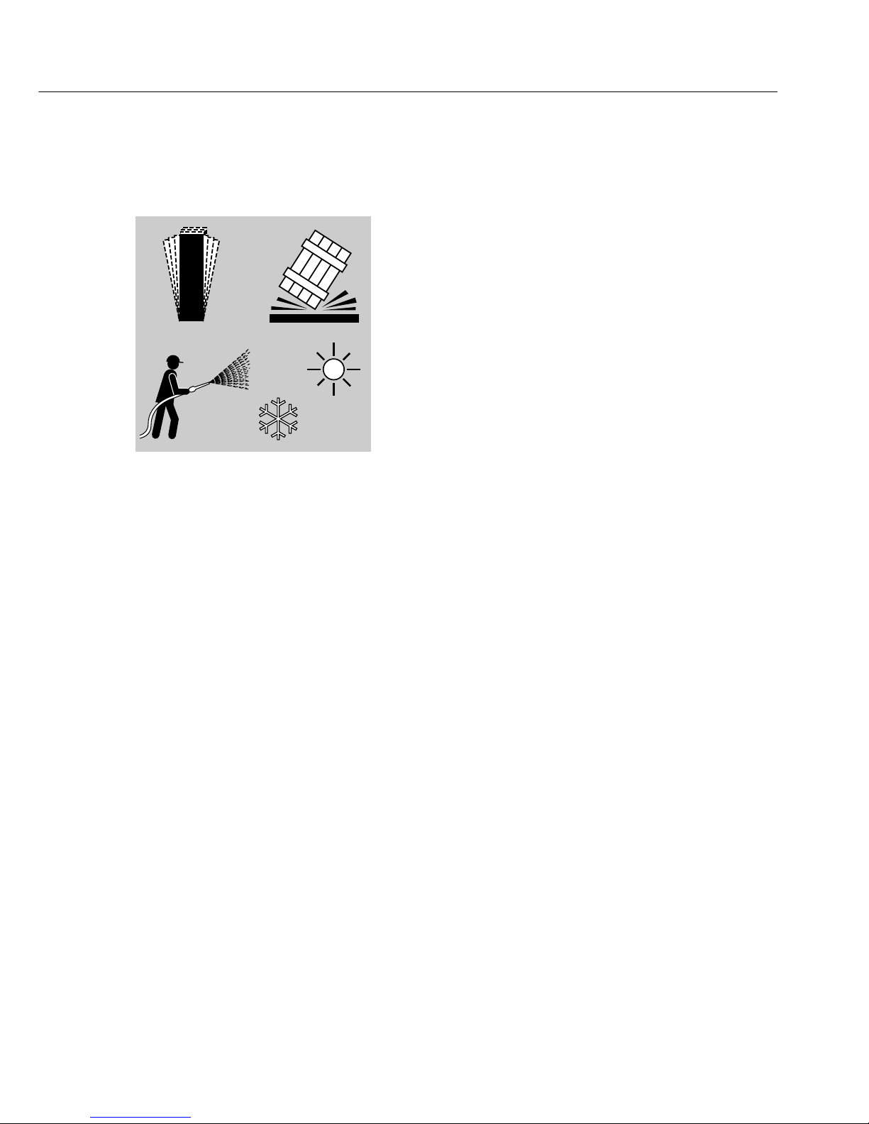
All components of the TopMix (TM01-X
paint-mixing weighing system are
restricted to an ambient operating tem-
perature range of 0°C to 40°C (32°F to
104°F . Make sure the place of installa-
tion is adequately ventilated to prevent
build-up of excessive heat.
!Do not use electrical equipment out of
doors. Prevent build-up of static elec-
tricity; e.g., on the dust cover or glass
parts. Provide an adequate connection
from the TM01-X terminal and the Ex-
link box (YCO09-Z to the equipotential
bonding conductor.
– Use the dust cover supplied to protect
the equipment from splashes of paint.
Observe the cleaning instructions when
cleaning the equipment.
– Have the equipment inspected at appro-
priate intervals for correct functioning
and safety by a trained technician.
Inspect the cables for damage regularly.
– Make sure operating personnel receive
sufficient training to recognize faulty
operating states and to introduce the
required measures in such cases (for
example, disconnecting the Ex-link box
from power .
Le al Notices
This equipment meets the prescribed
safety requirements. Improper use or
handling, however, can result in damage
and/or injury.
The manufacturer accepts no liability for
damage or injury resulting from failure
to observe these warnings and safety
precautions.
– When you use electrical equipment in
installations and under ambient condi-
tions subject to higher safety standards,
you must comply with the provisions as
specified in the applicable regulations
for installation in your country.
– The terminal and the Ex-link box
(YCO09-Z are not permitted for use in
legal metrology, medical applications,
hazardous areas or areas in which poten-
tially explosive dusts are present.
– The intrinsically safe terminal and the
Ex-link box (YCO09-Z are manufactured
in compliance with the valid harmonized
European standards of CENELEC:
EN 50014: 1997 A1+ A2
EN 50020: 2004
The TopMix can be operated with
intrinsically safe Sartorius weighing
instruments (e.g., PMA7500-X in Zone 1
hazardous areas (see “Verification of
Intrinsic Safety,”
Drawing No. 35960-740-60 A4
or 35960-740-61 A4
– The industrial protection rating of the
terminal and the Ex-link box (YCO09-Z
is IP40 in accordance with EN60529.
Handle the equipment carefully in keep-
ing with its IP rating. The place of use
must be secured accordingly.

5
Zone 1 Hazardous Areas
(Cate ory 2 Equipment)
– The TopMix (TM01-X is a Category 2
device in accordance with Council Direc-
tive 94/9/EC, approved for use in Zone 1
hazardous areas.
EC Type-Examination Certificate:
– KEMA 04ATEX1021X.
Explosion protection designation:
– EEx ib d[ib] IIB T4 and II 2 G
– The Ex-link box (YCO09-Z with the
designation:
– [EEx ib]IIB and II (2 G
according to EC Type-Examination
Certificate No.
– KEMA 04ATEX1021X,
is suited for installation only as peripher-
al electrical equipment outside the haz-
ardous area. It must be connected to
a power supply of at least 90 V and no
more than 264 V at a frequency of
48-62 Hz.
!If you use the equipment in a Zone 1
hazardous area outside Germany, you
must comply with the national electrical
code and safety regulations applicable in
your country. Ask your local Sartorius
office or dealer for information on the
legal regulations applicable in your
country.
!Proceed with extreme caution when
using pre-wired connecting cables, as
the pin assignments may not be compat-
ible with Sartorius equipment.
Use only cables and cable lengths
approved by Sartorius.
– The operator shall be solely responsible
for any damage or injuries that occur
when using cables not supplied by Sar-
torius.
!The Ex-link box (YCO09-Z may be
opened only when it is disconnected
from power, and only by trained techni-
cians. If the equipment is not discon-
nected from power, touching conductive
parts in the power supply wiring may be
fatal.
!Make sure the glass panel on the display
cannot be damaged (for example, by
falling objects during installation and
operation of the TM01-X terminal.
If the glass panel is damaged, the equip-
ment must be disconnected from power
immediately.
!Repair work may be performed only
by authorized service technicians who
have been trained by Sartorius and who
follow Sartorius’ standard operating pro-
cedures. Use only Sartorius spare parts.
Always make sure the equipment is dis-
connected from power before perform-
ing any installation, cleaning, mainte-
nance or repair work. If the equipment
housing is opened by anyone other than
persons authorized by Sartorius, this will
result in forfeiture of all claims under the
manufacturer’s warranty.
If you need assistance, contact your
Sartorius dealer or the Sartorius Service
Center.

6
Gettin Started
Unpackin the Equipment
§After unpacking the equipment, check it immedi-
ately for any visible sign of damage resulting
from rough handling during shipment.
$If any sign of damage is visible, refer to the
section entitled “Safety Inspection” in the chapter
entitled “Care and Maintenance.” It is a good
idea to save the box and all parts of the packaging
until you have successfully installed the equip-
ment. Only the original packaging provides the
best protection for shipment. Before packing the
equipment for shipment, unplug all connected
cables to prevent damage.
Equipment Supplied
The TopMix paint-mixing weighing system
includes the following components:
– Terminal (TM01-X with LC display and keypad
for use in Zone 1 hazardous areas
– Ex-link box (YCO09-Z for use outside the haz-
ardous area
– TopMix—Ex-link cable, part no. YCC01-
0038M20, for connecting the terminal (TM01-X
to the Ex-link box. Cable length: 20 m.
– TopMix–VGA video cable, part no. YCC01-
0037M20, for connecting the display and control
unit to the Ex-link box. Cable length: 20 m.
– PC video cable, part no. YCC01-0039M3, for
connecting a standard computer to the Ex-link
box outside the hazardous area. Cable length: 3 m
– TopMix—PC USB cable, part no. YCC01-0040M3,
for connecting a standard computer to the Ex-
link box outside the hazardous area. Cable
length: 3 m
– TopMix—PMA series cable, part no. YCC01-
0041M3, for connecting a weighing instrument.
Cable length: 3 m
– Dust cover, part no. YDC01TM, for the display
and control unit
– Power cord for the Ex-link box
– Installation instructions (this manual

7
Installation Instructions
To ensure fast and reliable results, avoid the
following when choosing locations for setting
up your terminal (TM01-X and Ex-link box
(YCO09-Z :
– Unstable or uneven surfaces
– Drafts
– Excessive moisture or chemical vapors
– Excessive heat (e.g., from a heater or exposure
to direct sunlight . Do not install the equipment
in a control cabinet or other poorly ventilated
location. If you use multiple Ex-link boxes,
do not stack them.
– Excessive vibration
Note:
Observe the warnings and safety precautions
included in these instructions.
– Before putting the equipment into operation,
make sure the power cord is properly connected.
It is particularly important to make sure the pro-
tective grounding conductor is connected to the
housing of the Ex-link box. All equipment must
be connected to the equipotential bonding con-
ductor by connecting the grounding cable (not
included in delivery to the grounding terminals
on each device.
The dimensions of the grounding cable are speci-
fied in national regulations for electrical installa-
tions. Installation must be performed by a trained
technician in accordance with national regula-
tions and acknowledged technological standards.
– Use only cabling and extensions approved by
Sartorius, as these are made in accordance with
the restrictions on permissible cable lengths
imposed by both the capacitance and inductivity
values (see the “Schedule to EC Type-Examina-
tion Certificate” and the requirements for electro-
magnetic compatibility.
– Do not connect devices to the Ex-link box that
are capable of subjecting the Ex-link box to peak
voltages exceeding 375 V.
°C

8
– Before putting the system into operation for the
first time, make sure there is no hazard of explo-
sion present at the place of installation of the
Ex-link box.
– If there is any indication that the equipment does
not function properly (e.g., display remains blank,
no display backlighting, etc. due to damage dur-
ing transport, disconnect the equipment from
power and notify your nearest Sartorius Service
Center.
Before connecting or disconnecting data cables
or control lines to or from the device, make sure
all equipment is disconnected from power.
The explosion-protected paint-mixing weighing
system must be set up in accordance with
acknowledged technological standards. These
include the national laws and regulations appli-
cable at the place of use.
– Before the paint-mixing system is operated in
a hazardous area, it must be inspected either by
a certified electrician or under the guidance and
supervision of a certified electrician to make sure
that the weighing system complies with the
applicable regulations.

9
Installin
the TopMix System
§Connect the TopMix—Ex-link cable
(YCC01-0038M20; length: 20 m to the terminal.
Tighten the connector.
§Connect the TopMix—VGA video cable
(YCC01-0037M20; length: 20 m to the terminal.
Tighten the fastening screws.
§Connect the weighing instrument
(e.g., PMA scale using the TopMix—PMA
series cable (YCC01-0041M3 .
Tighten the fastening screws.

10
§Connect the equipotential bonding conductor.
Use grounding cable (not included in delivery
to connect the grounding terminals on all devices
to the equipotential bonding conductor of the
power supply in use at the place of installation.
The dimensions of the grounding cable are speci-
fied in national regulations for electrical installa-
tions. Installation must be performed by a trained
technician in accordance with national regula-
tions and acknowledged technological standards.
§The terminal (TM01-X can be affixed to the wall
using the bore holes indicated (see arrows on the
mounting bracket (wall installation device .
Installin the Ex-link Box (YCO09-Z)
§Connect the TopMix—Ex-link cable
(YCC01-0038M20; length: 20 m to the Ex-link
box (YCO09-Z (Ex side .
Tighten the connector.

11
§Connect the TopMix—VGA video cable
(YCC01-0037M20; length: 20 m to the Ex-link
box (YCO09-Z (Ex side .
Tighten the fastening screws.
§USB port (see illustration :
Connect the TopMix—PC USB cable (YCC01-
0040M3; length: 3 m for a standard computer
to the Ex-link box outside the hazardous area
(PC side .
§Connect the PC video cable (YCC01-0039M3;
length: 3 m for a standard computer to the
Ex-link box outside the hazardous area (PC side .
Tighten the fastening screws.

12
§Monitor connection:
VGA control monitor, 800x600 pixels, outside the
hazardous area (PC side .
Computer setting: high color (16-bit
§Connect the equipment to power (PC side .
Note:
Observe the warnings and safety precautions
included in these instructions.
Note:
§The Ex-link box (YCO09-Z can be mounted
on the wall or on the underside of the table or
workbench.

13
Connectin the System to AC Power
The equipment is powered through the power
cord supplied. The Ex-link box (YCO09-Z has
a built-in AC adapter for operation with a power
supply between 90 and 264 V and a frequency
of 47 to 63 Hz. If the line voltage or frequency
exceeds these limits, or if the plug on the cable
does not match the standard used in your area,
please contact your supplier for assistance.
!The Ex-link box (YCO09-Z must be installed
outside the hazardous area.
Observe the following when operating the
TopMix (TM01-X in a Zone 1 hazardous area:
– Make sure the currently valid regulations and
guidelines for installing equipment in a Zone 1
area (in Germany, ElexV of 27 Feb 1980 are
strictly observed.
Switchin the TopMix On and Off
§The TopMix terminal (TM01-X is switched
on/off when the computer is switched on/off.
> The Ex-link box (YCO09-Z remains in standby
mode when the computer is switched off.
The standby mode is indicated by the LED on the
D-Sub connector.
When the computer is switched on, all five LEDs
are lit. The terminal switches on when the video
signal is detected.
§The backlighting of the weighing instrument dis-
play is activated when the supply voltage reaches
the TopMix display and control unit.
Note:
The TopMix runs a self-test when the computer
is switched on.
§Switch off the system when not in use.

14
Care and Maintenance
Cleanin
!Make sure no liquid enters the equip-
ment housing.
Do not use aggressive cleaning agents.
!Using jets of water or compressed air to
clean the equipment is not permitted.
Cleanin Stainless Steel Surfaces
Clean all stainless steel parts regularly.
Use a damp cloth or sponge to wipe
down stainless steel parts. You can use
any household cleaning agent that is
suitable for use on stainless steel. Then
wipe the equipment thoroughly to
remove all residues. Afterwards, allow
the equipment to dry. If desired, you
can apply oil to the cleaned surfaces as
additional protection.
Note:
Do not apply any cleaning agents to the
manufacturer’s ID label or printed
labels.
Corrosive Environment
$Remove all traces of corrosive sub-
stances on a regular basis.
Stora e and Shippin Conditions
– Allowable storage temperature:
-40 °C to +70 °C (-40° to +158°F
Service
Regular servicing by a Sartorius techni-
cian will ensure continuous correct
functioning of your equipment. Sarto-
rius offers service contracts with regular
maintenance intervals ranging from 1
month to 2 years. The optimum mainte-
nance interval depends on operating
conditions and tolerance requirements.
Repairs
!Defective equipment must be discon-
nected from power immediately. Repair
work must be performed by authorized
Sartorius service technicians using origi-
nal spare parts. Repairs performed by
untrained persons may result in consid-
erable hazards for the user. If the equip-
ment is still under warranty, send the
entire system to the factory for repairs.
Safety Inspection
Safe operation of the device is no
longer ensured when:
– there is visible damage to the device
– the device no longer functions properly
– the equipment has been stored for a rel-
atively long period under unfavorable
conditions
In this case, notify your nearest Sarto-
rius Service Center. Only service techni-
cians who are authorized by Sartorius
and who have access to the required
maintenance manuals are allowed to
perform maintenance and repair work
on the equipment. Before shipping your
TopMix to the factory for repairs:
– remove all paint residues
– disconnect all cables to prevent damage
to the equipment
– enclose a description of the defect

15
CMarkin
The TopMix equipment complies with the
following EC Directives and European
Standards:
Council Directive 89/336/EEC
“Electromagnetic compatibility (EMC ”
Applicable European Standards:
Limitation of emissions:
In accordance with product standard EN
61326-1 Class B
(residential area
Defined immunity to interference:
In acc. with product standard EN 61326-1
(industrial area
Note:
The operator shall be responsible for any
modifications to Sartorius equipment and
must check and, if necessary, correct these
modifications. On request, Sartorius will
provide information on the minimum oper-
ating specifications (in accordance with the
Standards listed above for defined immuni-
ty to interference .
73/23/EEC “Electrical equipment designed
for use within certain voltage limits”
Applicable European Standards:
EN 60950
Safety of information technology equip-
ment including electrical business equip-
ment
EN 61010
Safety requirements for electrical equip-
ment for measurement, control and labora-
tory use
Part 1: General requirements
If you use electrical equipment in installa-
tions and under ambient conditions subject
to higher safety standards, you must com-
ply with the provisions as specified in the
applicable regulations for installation in
your country.
Recyclin
The packaging protects the equipment
from damage during transport. After suc-
cessful installation of the equipment, you
should return this packaging for recycling.
For information on recycling options,
including recycling of used equipment,
contact your municipal waste disposal cen-
ter or local recycling depot.
Serial Number Codin
The month and year of manufacture are
encoded in the serial number as follows:
Y M M x x x x x
Y Year
1 2000–2006
2 2007–2013
3 2014–2020
4 2021–2027
5 2028–2034
6 2035–2041
7 2042–2048
8 2049-2055
9 2056-2062
The first digit represents a 7-year period
(see the table above ; the next 2 digits rep-
resent the month. Months are numbered
consecutively over the entire 7-year period,
starting at 13. Thus the number represent-
ing the month also indicates the specific
year of manufacture.
2000 13-24
2001 25-26
...
Example:
113xxxxx →January 2000
The individual devices are numbered con-
secutively in the last 5 digits, starting from
00000 again at the beginning of each
month.

16

17
Specifications
TopMix TM01-X with Ex-link box (YCO09-Z
Model TM01-X
Allowable ambient operating temperature range °C +5 to +40 (41° to 104°F
Housing dimensions (WxDxH :
TopMix display and control unit mm 420 x 444 x 396
Ex-link box mm 375 x 175 x 73
Net weight:
TopMix display and control unit, approx. kg 16.5
Ex-link box, approx. kg 3.2
AC power source V 100 – 240V ~
Frequency Hz 50 – 60
Power consumption (average VA 25
Designation [type of explosion protection]
Terminal TM01-X EEx ib d[ib] IIB T4 and II 2 G
(KEMA 04ATEX1021X
Ex-link box YCO09-Z [EEx ib] IIB II (2 G
(KEMA 04ATEX1021X
The terminal is suitable for use in
hazardous areas (in accordance with Council
Directive 94/9/EC rated to Zone 1 or 2 (Category 2 equipment
IP protection IP40
Accessories (Options)
Dust cover for display and control unit YDC01TM

Declaration of Conformity
18

19

20
Table of contents
Other Sartorius Accessories manuals

Sartorius
Sartorius Combics 3 Series User manual

Sartorius
Sartorius WZA224-LC User manual

Sartorius
Sartorius TopMix TM01-Y User manual

Sartorius
Sartorius IS...-X Series User manual

Sartorius
Sartorius IS 64 FEG-S0CE User manual

Sartorius
Sartorius WZA25-NC User guide

Sartorius
Sartorius Factory Series User manual

Sartorius
Sartorius BioPAT Pressure User manual

Sartorius
Sartorius Midrics 1 User manual

Sartorius
Sartorius WZ-L Series User manual