APS-30 SATEL 3
7. If necessary, connect the wiring from the alarm control panel to AWS output (output for
signalling 230 V AC power loss) and (or) to AWB output (output for signalling battery low
voltage or battery failure). During normal operation of the power supply unit, the signaling
output is shorted to the ground (0 V), but when any of the above mentioned causes
occurs, it becomes cut off from the ground.
Figure 2. Schematic view of AWS and AWB outputs.
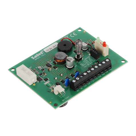
8. Using jumpers, set the time delay on the AC FAIL DELAY pins after which 230 V AC
power failure shall be signaled. Possible time delay settings:
0 seconds – Pins open
60 seconds – Pins shorted
600 seconds –
1800 seconds –
9. Using the BEEPER pins, determine, whether the beeper is to be switched on (jumper
on), or not (jumper off).
10. Using the BATT. CHARGE pins, determine the battery charging current (jumper on
- 0.5 A; jumper off – 1 A)
11. Switch on 230 V AC mains supply (if all connections are properly made, LEDs marked as
POWER and BATTERY should be ON).
12. After connecting the power supply, it is possible to measure the voltage across battery
cables. The correct voltage should be approx. 13.7 V.
13. Connect the battery according to the colour marking. If the battery is discharged, green
LED (BATTERY) will start flashing after approx. 4 minutes from switching on 230 V AC
mains supply. In case that the battery is connected after this period (green LED is
already flashing), the battery charging conditions shall be known after performing the
next test by the power supply – after approx. 12 minutes. Charging the battery is
signalled by a steady light of yellow LED, its brightness depends on charging current.
The second function of the yellow LED is signalling the test procedure for checking the
battery voltage. Every 4 minutes this diode is ON for several seconds, during which the
processor reduces the power supply voltage and the loads are powered from the battery.
The battery test function can be disabled by removing the jumper BATT. CHECK.
Disabling the test will also deactivate the battery failure signaling on the AWB output,
without, however, switching off the circuit which protects the battery from complete
discharge.
14. Next, the proper operation of failure monitoring circuits can be checked (with the BATT.
CHECK jumper set on):
Switch off AC power – the red LED (POWER) shall start flashing and the failure of AC
power shall be acoustically signalled by the power supply. After the time delay, set on the
pins, the status of AWS output shall change. When AC power is restored, LED will light
permanently, audible signaling shall be switched off and AWS output shall stop signalling
the AC power failure after the time delay set on the pins.

