Satel APS-30 S User manual

APS-30 S
Power supply aps-30_s_en 05/21
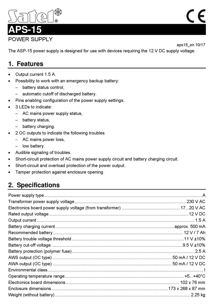
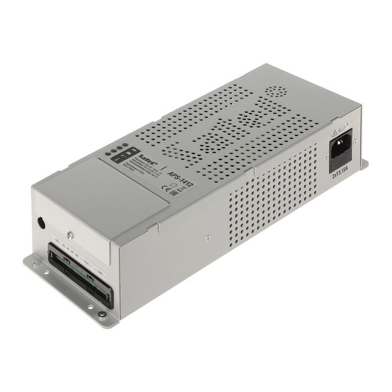
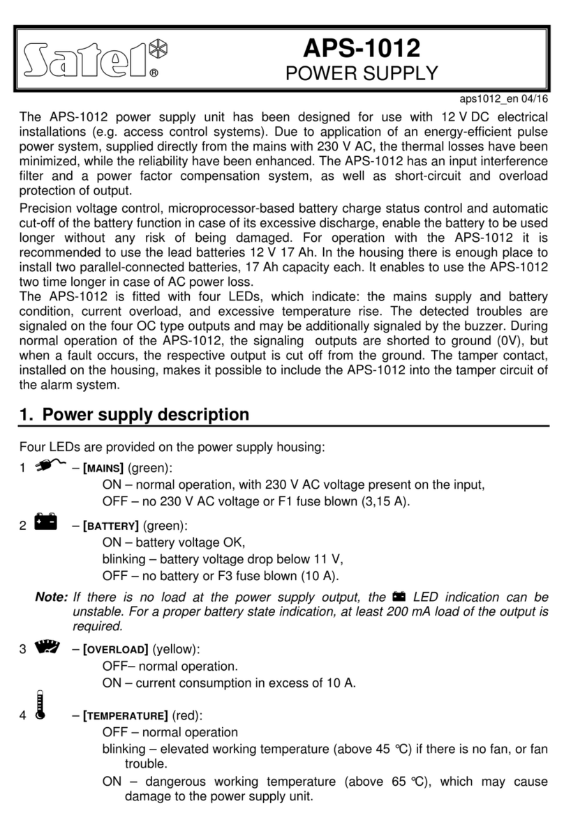
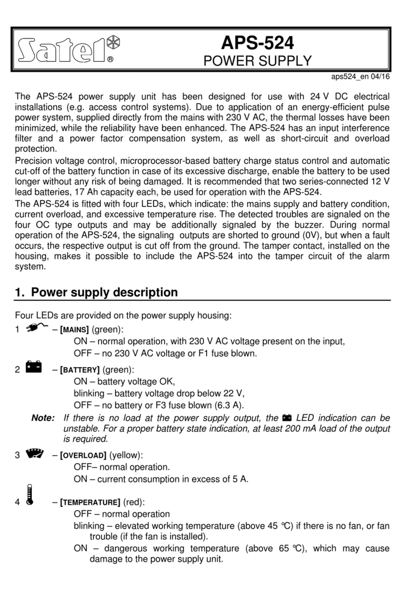
The APS-30 S switch mode power supply is designed for devices that require 12 VDC
nominal voltage.
The set includes: power supply, transformer, enclosure and additional accessories: tamper
switches, spacers, connecting cables for transformer, wall plugs (anchors) and screws.
1. Features
Nominal output voltage (according to IEC 38): 12 VDC.
Output voltage stabilization.
Battery status control and low battery disconnect system.
Ability to work without a battery connected.
Output current:
–operation with battery: 2,5 A / 2 A,
–operation without battery: 3 A.
Battery charging current: 0,5 A / 1 A (selectable).
Pins enabling configuration of the power supply settings.
3 LEDs to indicate:
–AC mains power supply status,
–battery status,
–battery charging.
2 OC outputs to indicate the following troubles:
–AC mains power loss,
–low battery.
Acoustic signaling of troubles.
Electronic short-circuit protection of AC mains power supply circuit.
Short-circuit protection fuse for battery charging circuit (T 3,15 A).
Electronic short-circuit and overload protection of the power output.
Tamper protection against enclosure opening and removal from mounting surface.

2 APS-30 S SATEL
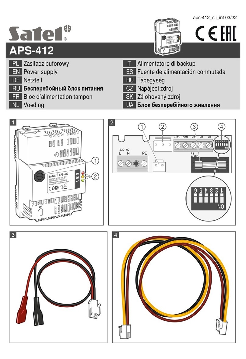
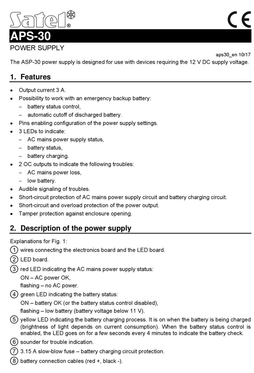
2. Description of the power supply
wires connecting the electronics board and the LED board.
LED board.
red LED to indicate the AC mains power supply status:
ON –AC power OK,
flashing –no AC power.
green LED to indicate the battery status:
ON –battery OK (or the battery status control disabled),
flashing –low battery (battery voltage below 11 V).
yellow LED to indicate the battery charging process. It is ON when the battery is being
charged (brightness of light depends on current consumption). When the battery status
control is enabled, the LED goes ON for a few seconds every 4 minutes to indicate that
the battery is tested.
sounder to indicate trouble.
3.15 A slow-blow fuse –battery charging circuit protection.
cables to connect the battery (red +; black -).
pins for configuring the power supply operating parameters. For how to configure the
power supply, refer to figures 2-5 (see: “Configuring the power supply”).

SATEL APS-30 S 3
Terminals
AC –power input (17-24 VAC).
COM –common ground.
+12V –power output (13.6-13.8 VDC).
AWS –OC type output to indicate the loss of 230 VAC power.
AWB –OC type output to indicate low voltage or failure of the battery.
In the normal state, the OC type outputs are shorted to ground (0 V), but when a trouble
occurs, the output is disconnected from ground.
3. Configuring the power supply
Beeper for signaling trouble
You can enable / disable the acoustic signaling of trouble (Fig. 2):
jumper on –signaling enabled,
jumper off –signaling disabled.
Delay of AC power failure reporting
You can select the time that must pass after AC power loss before the AWS output turns on.
Available settings are shown in Fig. 3.

4 APS-30 S SATEL
Battery charging current
You can select the battery charging current (Fig. 4):
jumper on –0.5 A,
jumper off –1 A.
Battery check
You can enable / disable the battery testing mode (Fig. 5):
jumper on –mode enabled,
jumper off –mode disabled.
If you disable this mode, indication of low voltage / power supply failure on the AWB output
will be turned off.
4. Installation
Disconnect power before making any electrical connections.
The transformer should be permanently connected to the 230 VAC mains supply. Before you
make the cabling, familiarize yourself with the electrical installation of the facility. Make sure
that the circuit you choose for powering will be always alive. The circuit should be protected
with a proper safety device. The owner or user of the power supply should be instructed on
how to disconnect the transformer from the mains (e.g. by indicating the fuse which protects
the supply circuit).
A 12 V lead-acid sealed battery can be connected to the power supply as a backup power
source. The power supply enclosure can accommodate a battery with 7 Ah capacity.
Do not use batteries other than the recommended ones.
Do not discard used batteries. They should be disposed of in accordance with
the existing rules for environment protection.

SATEL APS-30 S 5
The sum of currents consumed by the devices to be supplied by the APS-30 S power supply
may not exceed:
2,5 A / 2 A if a battery is connected to the power supply,
3 A if no battery is connected to the power supply.
1. Place the enclosure base on the wall and mark the location of mounting holes (Fig. 6).
During installation, remember about the mounting hole in the tamper element indicated by
the symbol in Fig. 6.
2. Drill the holes for wall plugs (anchors). The wall plugs (anchors) delivered with the power
supply are intended for concrete, brick, etc. For other types of surface (drywall,
styrofoam), use the appropriately selected wall plugs.
3. Run the wires through the openings in the enclosure base (Fig. 6).
4. Fasten the enclosure base to the wall with four screws (Fig. 6). If you have trouble laying
the cables, use spacers to mount the enclosure at a distance of 6 mm from the surface.
5. Using a screw, secure the tamper element to the wall (Fig. 6).
6. Screw down the transformer to the enclosure with three screws (Fig. 7).
7. Connect the 230 VAC power cables to the corresponding transformer terminals.
Never connect two devices with a power supply unit to a single-section
transformer.
Before connecting transformer to a circuit from which it will be powered, make
sure the circuit is de-energized.
8. Solder the leads to the included tamper switches.

6 APS-30 S SATEL
9. Place the tamper switches in the appropriate holders (Fig. 7). One of the switches should
be placed in the holder on the post so that it is closed after the cover is replaced.
The other switch should be placed in the enclosure base holder so that the metal plate is
pressed against the tamper element.
10.Insert the plastic plugs for fastening the PCB into the holes marked with the symbol
(Fig. 8).
11.Break off the separate LED board from the electronics board.
12.Mount the electronics board on the plugs.
13.Using two screws, secure the LED board from above to the post inside the enclosure
(Fig. 9). Make sure the LEDs enter their corresponding holes according to the symbols on
the enclosure cover:
–red LED (AC supply),
–green LED (battery status),
–yellow LED (battery charging).
14.Connect the terminals of transformer secondary winding to the power supply AC terminals
(use the black leads delivered in the bag).
15.Connect the devices to the power supply outputs (+12V and COM terminals).
16.You can connect e.g. LEDs to the outputs that signal troubles or connect these outputs to
the zones of the alarm control panel or other device which is to supervise the power
supply operation.

SATEL APS-30 S 7
17.Using jumpers, set the power supply operating parameters (see: “Configuring the power
supply”).
18.Insert the battery in the enclosure (Fig. 9) and connect it to the dedicated leads
(the battery’s positive terminal to RED lead, negative terminal to BLACK lead).
19.Replace the cover and secure it to the enclosure base with two screws. Cover the screw
holes with special hole plugs included in the delivery set.
20.Turn on 230 VAC power supply in the circuit to which the transformer is connected.
The power supply unit will start (LEDs will light up).
5. Battery testing by the power supply
The battery is tested every 4 minutes which is indicated by lighting up of the yellow LED .
A full test of the battery charge status can take up to 12 minutes. If the battery voltage drops
below 11 V, the power supply will indicate trouble on the AWB output, and the green LED
will start flashing (optionally, the trouble can be signaled acoustically). If the voltage
drops to about 9.5 V, the battery will be disconnected.
6. Specifications
Power supply type (according to EN 50131)............................................................................A
Transformer power supply voltage...............................................................................230 VAC
Electronics board power supply voltage (from transformer)....................................17...24 VAC
Nominal output voltage (according to IEC 38) ...............................................................12 VDC
Output current
operation with battery connected..................................................................................3 A
operation without battery connected................................................................. 2.5 A / 2 A
Battery charging current (selectable)........................................................................ 0.5 А / 1 А
Recommended battery ............................................................................................ 12 V / 7 Ah
Current consumption of power supply circuits .................................................................80 mA
Battery failure voltage threshold ...............................................................................11 V ±10%
Battery cut-off voltage..............................................................................................9.5 V ±10%
OC type outputs (AWS, AWB).........................................................................50 mA / 12 VDC
Environmental class..................................................................................................................I
Operating temperature range...................................................................................+5...+40 °C

8 APS-30 S SATEL
Electronics board dimensions...............................................................................140 x 99 mm
Enclosure dimensions............................................................................... 266 x 286 x 100 mm
Weight (without battery).................................................................................................2.45 kg
The declaration of conformity may be consulted at www.satel.eu/ce
SATEL sp. z o.o. •ul. Budowlanych 66 • 80-298 Gdańsk • POLAND
tel. +48 58 320 94 00
www.satel.eu
Table of contents
Other Satel Power Supply manuals