6 APS-1412 SATEL
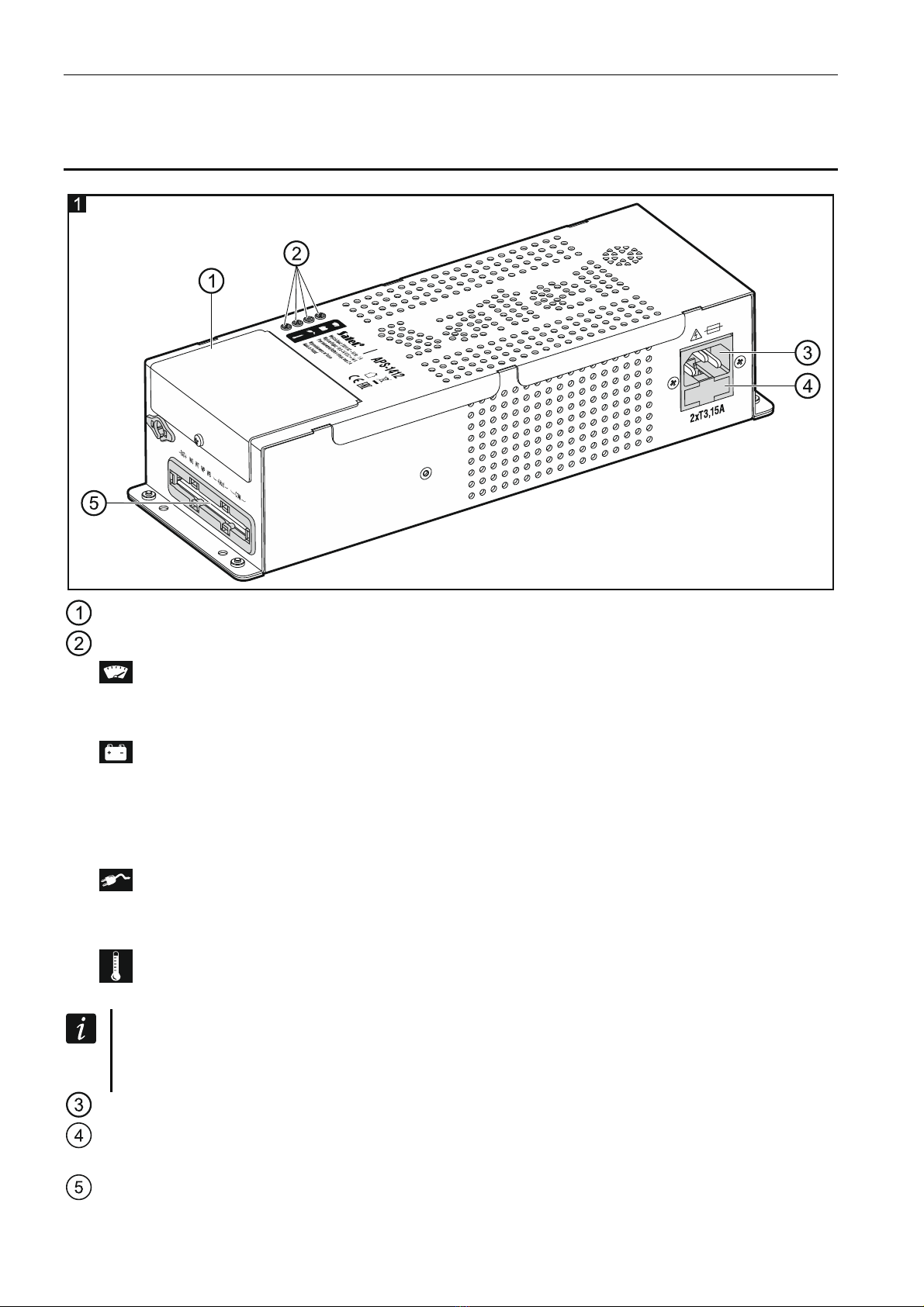
1. Remove the screw securing the cover of power supply terminals (Fig. 5).
2. Remove the cover of power supply terminals (Fig. 6).
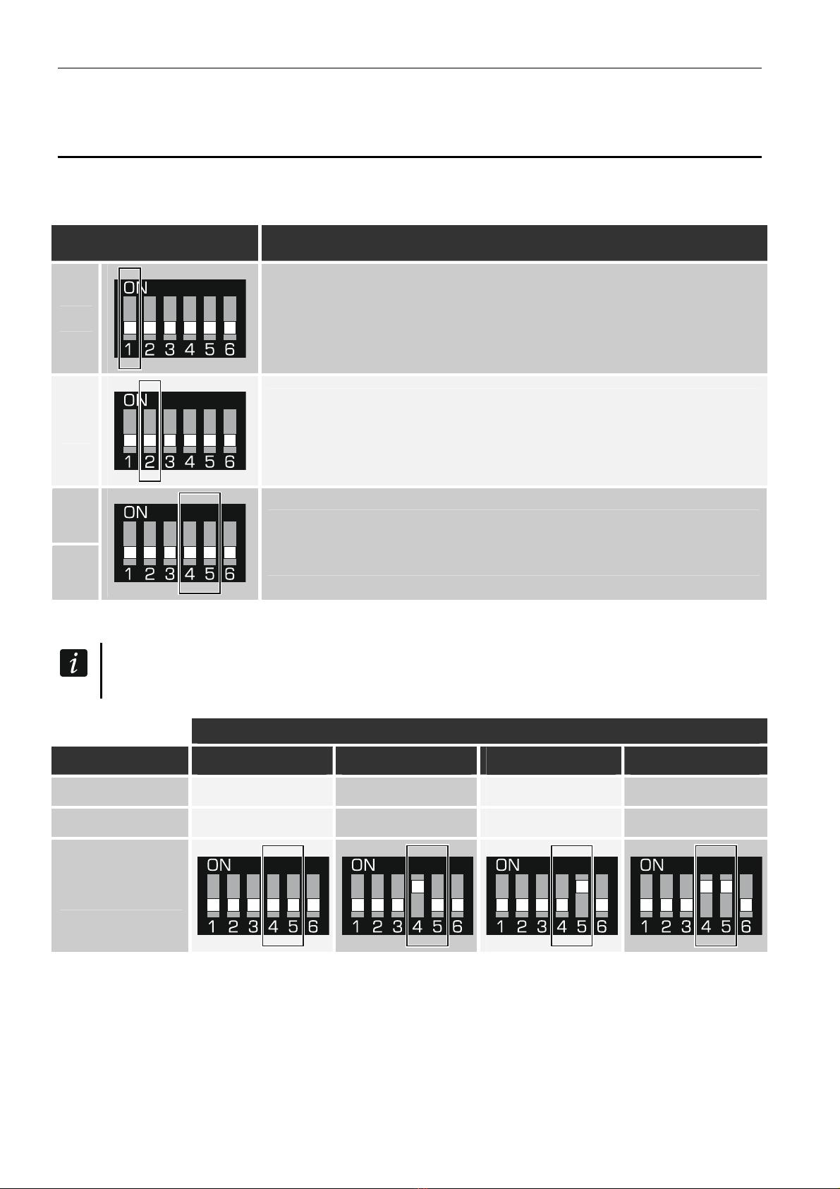
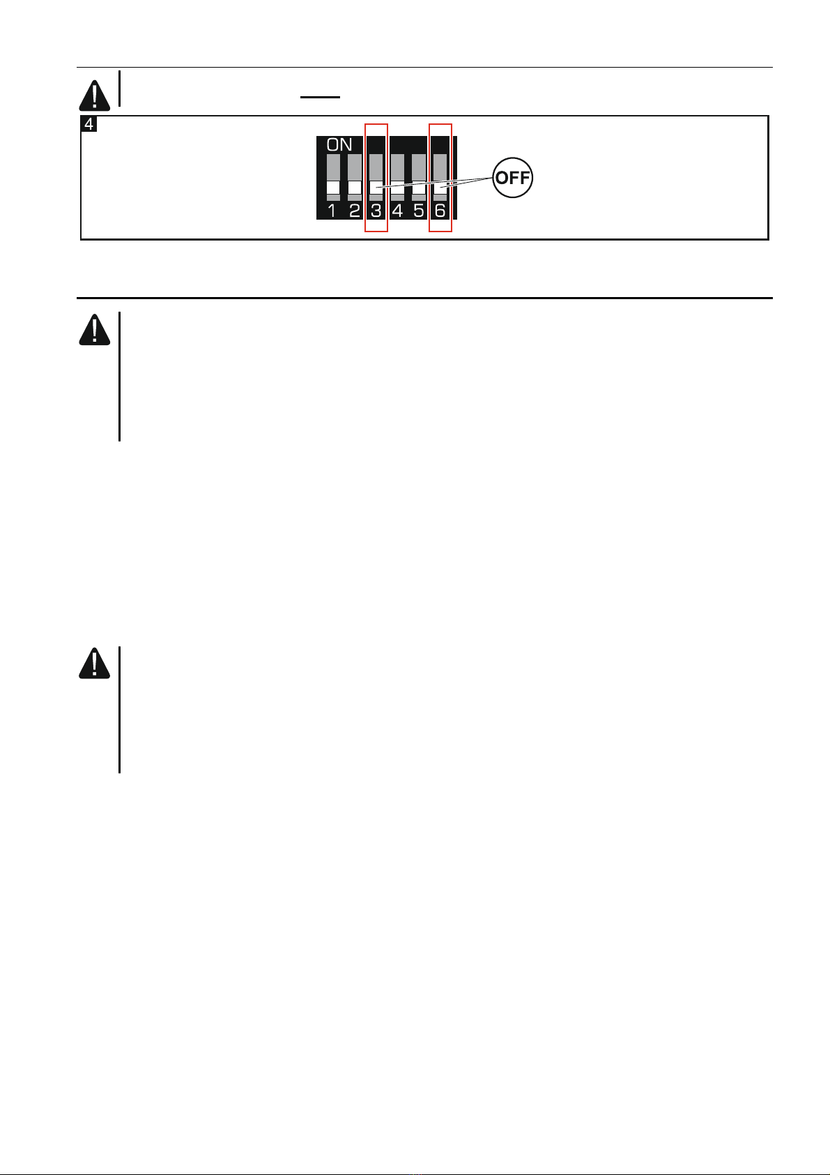
3. Use the DIP switches to configure the power supply (see “Configuring the power supply”).
4. If the power supply is to be integrated with a SATEL device, use the cable delivered with
the power supply to connect the power supply and the device. Pass the cable through the
opening in the enclosure (Fig. 7).
5. Connect devices to the power supply outputs (terminals +Vout and COM).
Remember that the cables connecting the + Vout power outputs to the devices
should be evenly loaded with current.
If you want to use the maximum power supply current of 14 A, connect the loads
so that each + Vout output supplies devices with a total current consumption of
about 5 A. To make connections, it is advisable then to use wires with
a minimum cross section of 1.5 mm2.
6. To the trouble signaling outputs, you can, for example, connect LEDs, relays, or connect
them to the inputs of control panel or other device which is to supervise the power supply
operation.
7. Connect the battery to the - BAT + terminals.
If the +Vout power supply outputs are loaded with 12 A current, it is
recommended that you use a minimum 4 mm2cross-section wires for battery
connection. The wires should be as short as possible.
8. Replace the cover of power supply terminals.
9. Replace and tighten the screw to secure the power supply terminals cover.
10.Connect the power cable to the power supply socket (Fig. 8).
11.Insert the power cable plug into the 230 VAC socket. The power supply will signal the
presence of voltage with 1 beep, and the LED will go on.