Satel APS-1012 User manual

®
APS-1012
POWER SUPPLY
aps1012_en 04/16
The APS-1012 power supply unit has been designed for use with 12 V DC electrical
installations (e.g. access control systems). Due to application of an energy-efficient pulse
power system, supplied directly from the mains with 230 V AC, the thermal losses have been
minimized, while the reliability have been enhanced. The APS-1012 has an input interference
filter and a power factor compensation system, as well as short-circuit and overload
protection of output.
Precision voltage control, microprocessor-based battery charge status control and automatic
cut-off of the battery function in case of its excessive discharge, enable the battery to be used
longer without any risk of being damaged. For operation with the APS-1012 it is
recommended to use the lead batteries 12 V 17 Ah. In the housing there is enough place to
install two parallel-connected batteries, 17 Ah capacity each. It enables to use the APS-1012
two time longer in case of AC power loss.
The APS-1012 is fitted with four LEDs, which indicate: the mains supply and battery
condition, current overload, and excessive temperature rise. The detected troubles are
signaled on the four OC type outputs and may be additionally signaled by the buzzer. During
normal operation of the APS-1012, the signaling outputs are shorted to ground (0V), but
when a fault occurs, the respective output is cut off from the ground. The tamper contact,
installed on the housing, makes it possible to include the APS-1012 into the tamper circuit of
the alarm system.
1. Power supply description
Four LEDs are provided on the power supply housing:
1 – [MAINS](green):
ON – normal operation, with 230 V AC voltage present on the input,
OFF – no 230 V AC voltage or F1 fuse blown (3,15 A).
2 – [BATTERY](green):
ON – battery voltage OK,
blinking – battery voltage drop below 11 V,
OFF – no battery or F3 fuse blown (10 A).
Note: If there is no load at the power supply output, the LED indication can be
unstable. For a proper battery state indication, at least 200 mA load of the output is
required.
3 – [OVERLOAD] (yellow):
OFF– normal operation.
ON – current consumption in excess of 10 A.
4 – [TEMPERATURE] (red):
OFF – normal operation
blinking – elevated working temperature (above 45 °C) if there is no fan, or fan
trouble.
ON – dangerous working temperature (above 65 °C), which may cause
damage to the power supply unit.

2 SATEL APS-1012
The APS-1012 is fitted with a fan, which ensures air circulation that decreases operation
temperature. When power supply temperature inside housing is above 45 °C, the processor
turns on the fan and, if there is no proper fan rotation, the [TEMPERATURE] LED starts
blinking. When the temperature is above 65 °C the red [TEMPERATURE] LED goes on and the
AWT output goes into active mode (disconnection from common ground). A drop in
temperature below 65°C will extinguish the LED steady light. The fan will stop when the
temperature drops below 45°C.
If the power supply output is shorted to the common ground (mount failure, cable fault) the
power supply is turned off – all four LEDs start blinking. This situation last until the failure is
removed. The short circuit may damage the F3 fuse in the battery circuit (if the battery was
connected).
Explanations to Figure 2:
1 – F1 mains fuse T3.15 A – input circuit protection.
2 – F3 fuse T10 A – protection of battery charging circuit.
3 – battery connecting cables 12 V (red +; black -).
4 – pins for setting power supply working parameters – symbol on the electronics
board denotes shorted pins (jumper on), denotes open pins (jumper off). By default,
jumpers are set on all pins.
AC FAIL DELAY – determination of the time that must elapse from the moment of AC
supply failure to the moment of signaling the same on the AWS output
(1800 or 10 seconds). By default, 1800 seconds.
BATT. CHARGE – determination of the battery charging current (2 A – pins open or 4 A
– pins shorted). By default, 2 A.
Note: To short the charging time of the high capacity battery the battery charging current has
been changed and it is higher than shown on the electronics board.
BATT. CHECK – battery test enabled/disabled. Disabling the test does not disable the
battery discharge control feature. By default, the battery test is enabled.
BEEP – audible trouble signal enabled/disabled. By default, the buzzer is enabled.
5 – buzzer – audible trouble signal.
6 – FAN – connector for connection of a fan.
Fig. 1. Fan connector description.
GND – fan ground
+12V – fan supply output
IMP – impulse input (fan
rotation)

APS-1012 SATEL 3
Fig. 2. View of electronics board.

4 SATEL APS-1012
Description of terminals:
230 and AC – mains power supply inputs (230 V AC).
+U – power supply outputs (13.6 – 13.8 V DC). Total current capacity of outputs
10 A.
COM – common ground (0V).
AWT – alarm output (OC): excessive permissible working temperature.
AWB – alarm output (OC): low battery voltage – below 11 V.
AWP – alarm output (OC): excessive permissible overload current – current
consumption over 10 A.
AWS – alarm output (OC): loss of 230 V AC – output activation delay 1800 s or 10 s.
2. Installation
Prior to commencement of installation, load balance of the power supply should be drawn up.
The current derived from the APS-1012 by external devices must not exceed 10 A.
During operation, the APS-1012 should be permanently connected to the mains supply.
Therefore, get yourself familiar with electrical installation in the building before you proceed to
making the cable connections. To supply the device, you should choose a circuit which is
always alive and suitably protected.
The power supply should only operate while being permanently connected to mains supply.
Hence, before making the connections it is necessary to familiarize with the electric system in
the facility. For powering the device choose the circuit which is always live. The power supply
circuit should be protected with a proper fuse.
Before connecting a device to the power supply circuit from which it will be
powered, make sure the circuit is not alive.
1. Attach the mounting (plastic) pins to the back side of the housing.
2. Mount the power supply housing in selected location and connect all electric leads .
3. Put the APS-1012 board on the pins.
4. Fix the LED board to the housing lid with two steel sheet metal screws (green LEDs in upward
position).
5. Connect the 230 V AC power wires to the 230 V and AC terminals of the APS-1012. Connect the
grounding wire to the terminal situated inside, on the rear panel of the metal housing and marked
by the ground symbol , connect a plug of the fan to the FAN connector.
6. Connect the supply cables for external devices to the terminals +U and COM on the APS-1012
board.
7. If necessary, make use of the trouble signaling outputs (e.g. to control relays or connect to the
control panel zones).
Fig. 3. Schematic view of AWS, AWP, AWB and AWT outputs.
AWS, AWP,
AWB, AWT
AWS, AWP,
AWB, AWT
10 k
4.7 k
10 R
BC847B
SMAJ30

APS-1012 SATEL 5
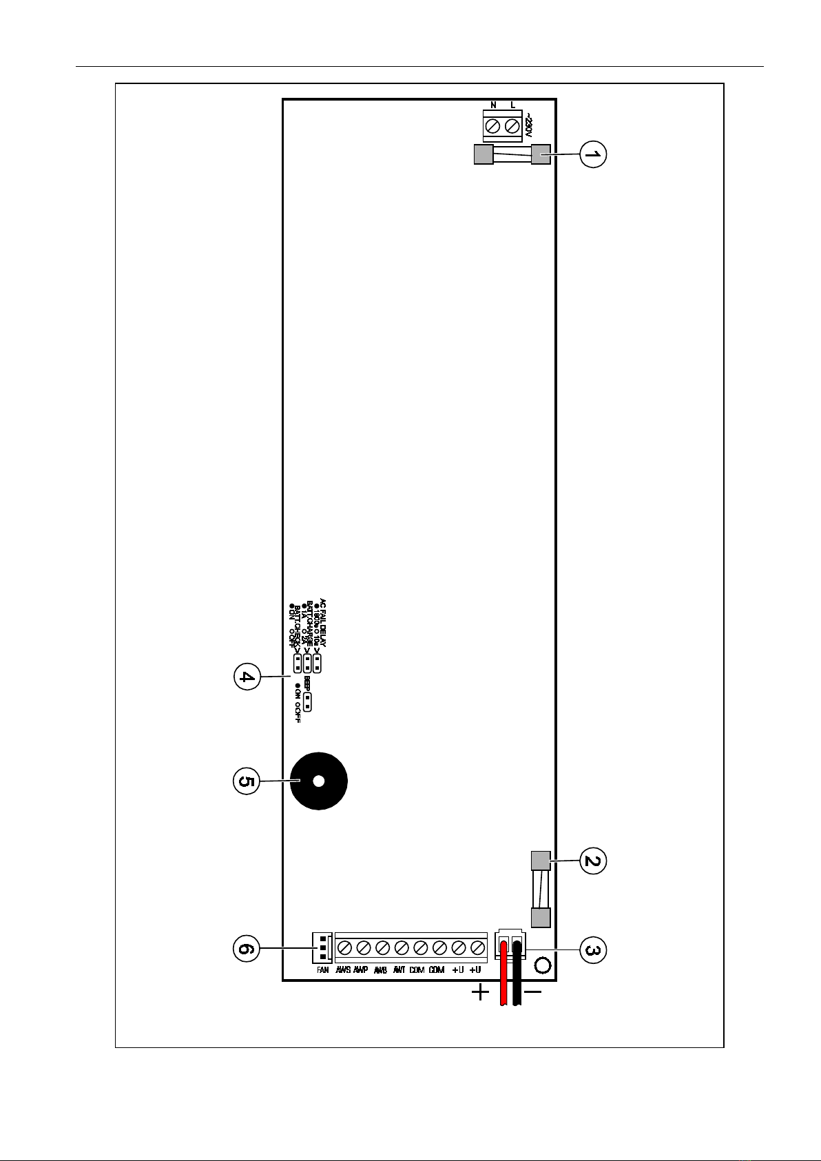
8. By putting jumpers on the AC FAIL DELAY pins, set the time delay after which 230 V AC
mains failure will be signaled on the AWS output. This setting specifies also the AWS
output restore time (when output goes back to its normal state), which must elapse from
the end of a failure.
Possible time delay settings:
1800 seconds – Pins shorted
10 seconds – Pins open
9. Using the BEEP pins, determine, whether the buzzer is to signal troubles (jumper on), or
not (jumper off).
In order to avoid the risk of electric shock, put and remove jumpers only in
deenergized state, i.e. with power supply disconnected.
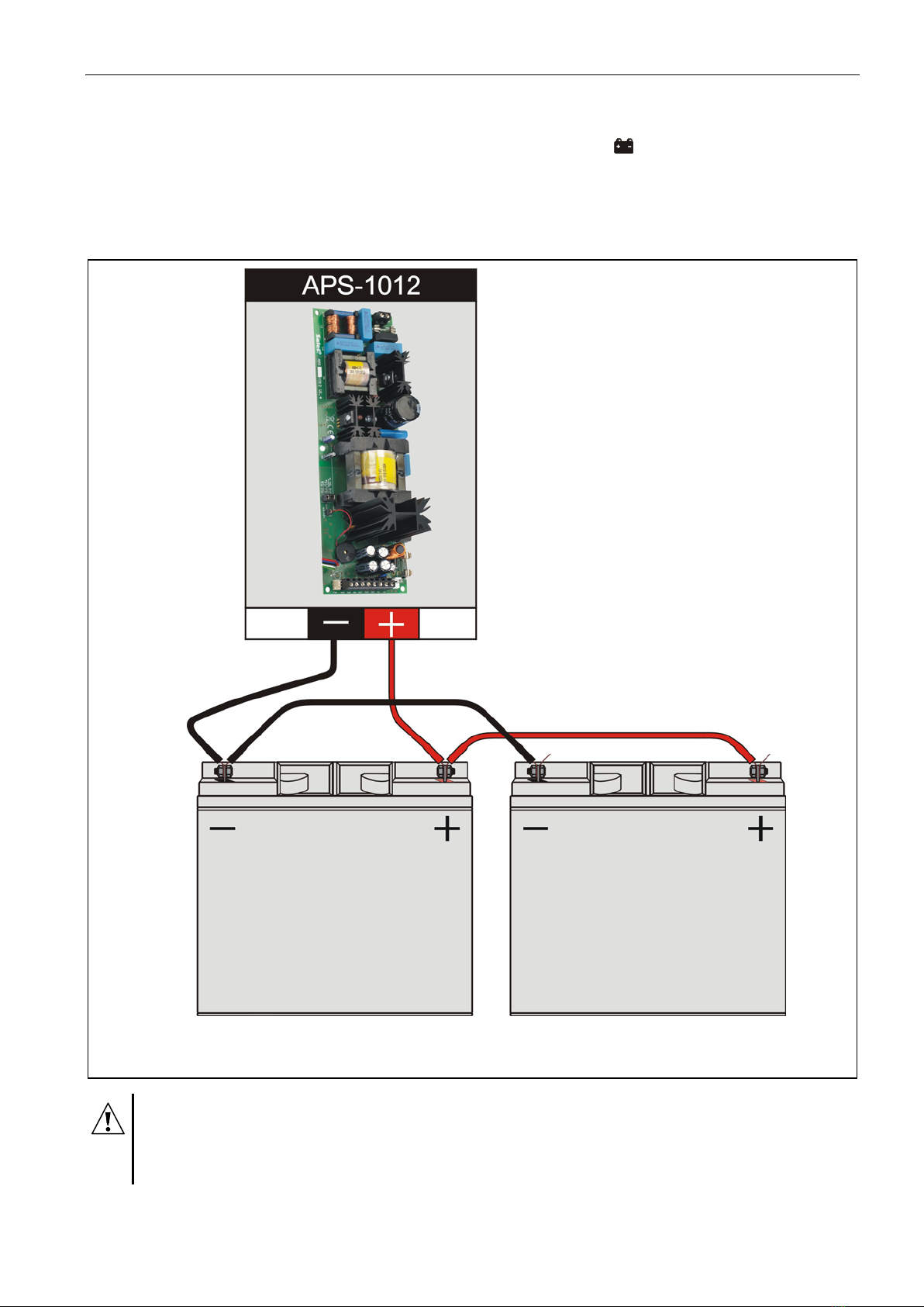
10.Connect the batteries according to the color markings.
The green LED [BATTERY] lights up as soon as 230 V power supply is on, however the
battery charge status will only be known after a full test, i.e. after approx. 12 minutes. The
battery charge status check is performed every 4 minutes and lasts some ten to twenty
seconds. During the tests, the processor reduces the power supply voltage to approx.
10,5 V, and the loads are switched over to battery supply. If the battery voltage drops to
approx. 11 V during three consecutive cycles, the APS-1012 will report a trouble, and
when the voltage drops down to 9,5 V, the APS-1012 will disconnect the battery to
prevent it from being fully discharged and damaged.
After completion of the test, the LED will remain ON if the APS-1012 detects presence of
a charged battery, or will start blinking if the battery is discharged, or will go out, if there is
no battery supply.
Note:If the battery is not detected after reconnection, the power supply circuit will only
detect the presence of the battery on the AWB output when a full test is completed
(approx. 12 min.).
The battery test may be optionally disabled – to do so, remove the BATT. CHECK
jumper. Disabling the test will also deactivate the battery trouble signaling on the AWB
output, however it will not disable the circuit protecting the battery from complete
discharge.
Note: Due to the risk associated with a rapid charge equalization when two batteries with
a capacity of 17 Ah are connected in parallel, the following rules must be respected:
−use only two identical batteries (the same manufacturer and type),
−before connection, charge both batteries independently with an external charging
device until the final voltage is reached, according to the given type of battery,
−if the battery replacement is necessary, replace both batteries at the same time,
making sure that the abovementioned rules are complied with.
11.Switch on 230 V AC power supply (if all connections have been made properly, the LEDs
[MAINS] and [BATTERY] should come on, while the LEDs [OVERLOAD] and
[TEMPERATURE] should remain off).
12.Then, you can check the trouble control circuits for proper functioning (with BATT.
CHECK jumper on):
Disconnect mains supply – the [MAINS] LED will go out and the APS-1012 will start
audibly signaling the trouble. After the time set on the pins has elapsed, the AWS output
status will change. After restoring the mains, the LED will come on with steady light, the

6 SATEL APS-1012
sound will be muted, and – after expiry of the time set on the pins – the AWS output will
stop signaling trouble.
Disconnect battery – after approx. 12 minutes the green [BATTERY] LED will go out
and the APS-1012 will start audibly signaling the trouble. The AWB output will signal
emergency condition. Reconnecting the battery will stop the trouble signaling by the LED
indicator and buzzer after approx. 12 minutes. When the APS-1012 has been installed
and tested for operation, its housing can be closed.
Fig. 4. Parallel connection of two batteries. The connection can be performed using the
cables available in the device delivery set.
As the APS-1012 has no isolating switch to disconnect the mains supply, it is
important that the user/owner of the device be advised on how it should be
disconnected from the mains (e.g. by indicating the fuse which protects the
supply circuit on the electric switchgear).

APS-1012 SATEL 7
3. Specifications
Type of power supply unit........................................................................................................A
Supply voltage............................................................................................................230 V AC
Rated output voltage.....................................................................................................12 V DC
Current capacity..................................................................................................................10 A
Maximum battery charging current (switchable) ........................................................2 A or 4 A
Energy efficiency .......................................................................................................up to 84%
Recommended battery ...................................................................................... 2 × 12 V/17 Ah
Load-carrying capacity, outputs: AWS, AWB, AWP, AWT (OC type) .....................max. 50 mA
Operating temperature range (Class I) ....................................................................+5...+45 °C
Electronics board dimensions............................................................................... 233 x 73 mm
Housing dimensions ..................................................................................403 x 323 x 100 mm
Weight (without battery)................................................................................................. 3.44 kg
WARNING
This is a Class A device. It may cause radio interference in residential environment. In such
cases, the user may be required to apply suitable countermeasures.
The control panel power supply unit has been designed for work with lead
batteries or other batteries with a similar charging curve. Using any other
batteries than recommended may cause a blow-up.
The batteries, when used-up, must not be thrown away, but disposed of as required by the
existing regulations (European Directives 91/157/EEC and 93/86/EEC).
The latest EC declaration of conformity and certificates are available for
downloading on our website www.satel.pl
SATEL sp. z o.o. • ul. Budowlanych 66 • 80-298 Gdańsk • POLAND
tel. + 48 58 320 94 00
www.satel.eu
Table of contents
Other Satel Power Supply manuals