7. Using four screws, fasten the enclosure base to the wall (the two lower screws also
secure the battery shelf).
8. Using a screw, fasten the tamper element to the wall.
9. Using four screws, fasten the inner insert (two extra screws are provided in the plastic
bag).
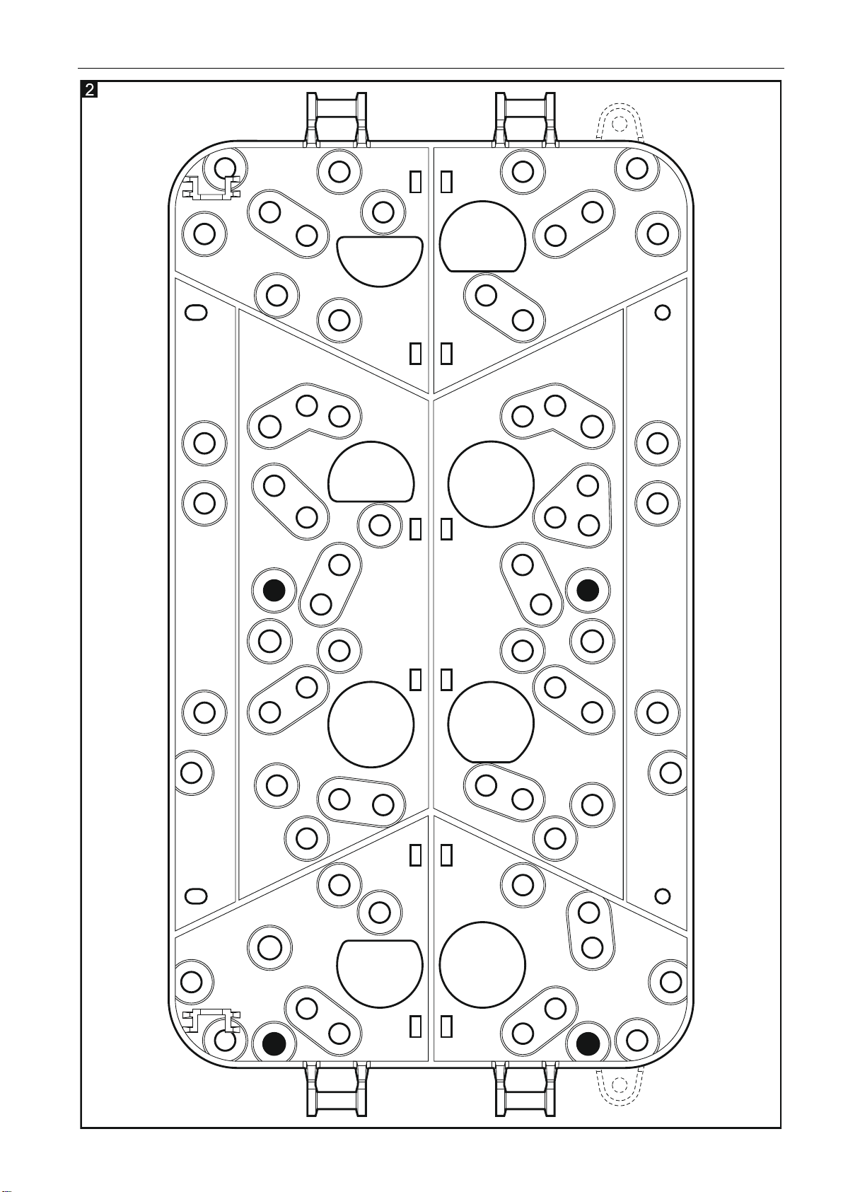
10.Insert the plastic plugs for fastening the electronics board in their respective holes.
The holes are shown in black in Figure 2.
11.Using three screws, attach the transformer to the base.
12.Connect the 230 VAC power leads to the corresponding transformer terminals.
Never connect two devices with a power supply unit to a single-section transformer.
Before connecting transformer to a circuit from which it will be powered, make sure
the circuit is de-energized.
Transformer capacity must match the DC power supply output capacity.
13.The tamper switch with PCB is to be screwed from above to the post inside the enclosure
so that it is closed after the cover is replaced.
14.Solder the leads to the other tamper switch. Place the contact in the enclosure base
holder so that the metal plate is pressed against the tamper element.
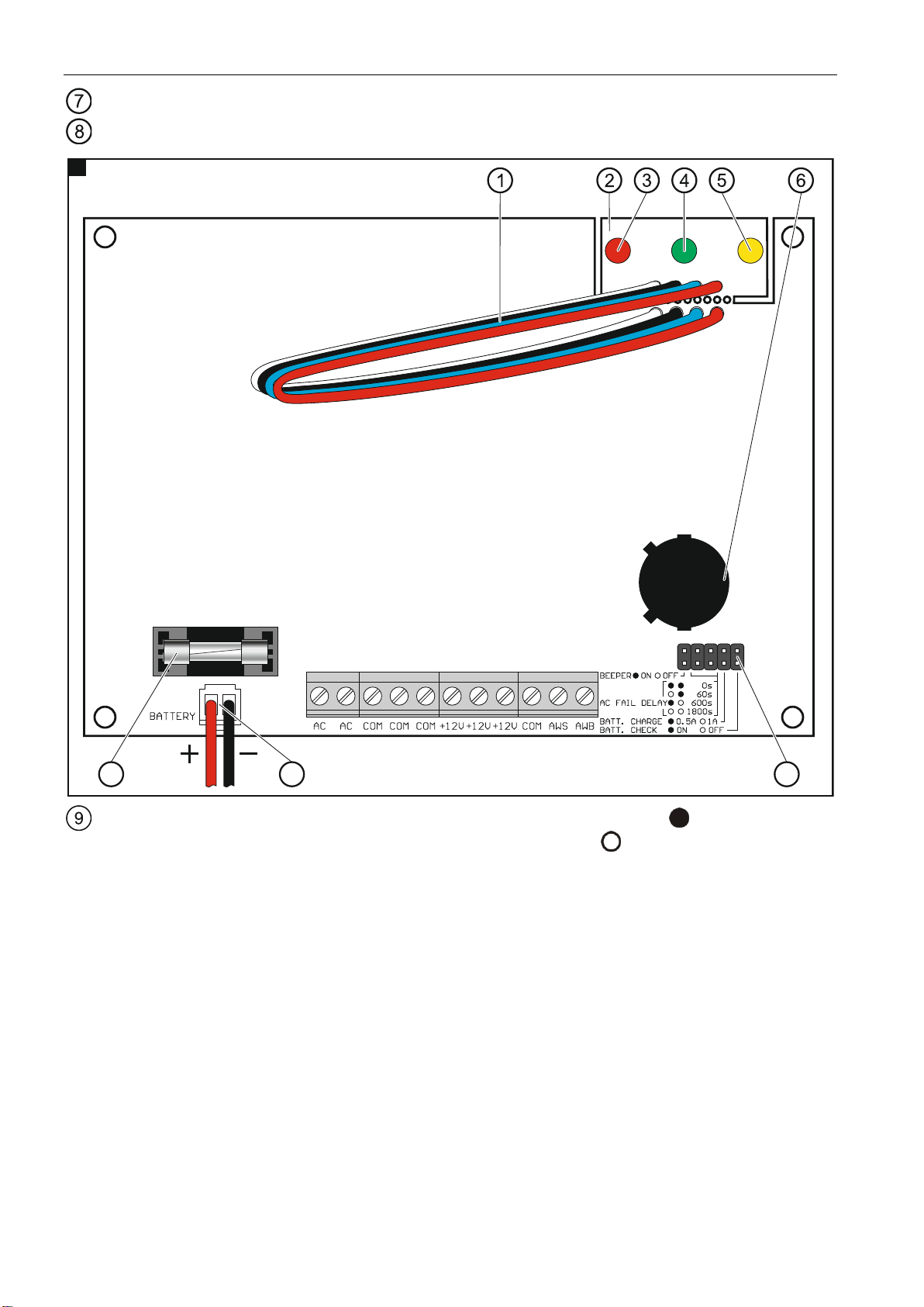
15.Break off the separate LED board from the electronics board.
16.Mount the electronics board on the plugs.
17.Using two screws, secure the LED board from above to the post inside the enclosure.
Make sure the LEDs enter their corresponding holes according to the designations on the
enclosure cover:
–red LED (AC supply),
–green LED (battery status),
–yellow LED (battery charging).
18.Connect the terminals of transformer secondary winding to the power supply AC terminals
(use the black leads delivered in the bag).
19.Connect the devices to the terminals +12V and COM.
20.You can connect LEDs, relays etc. to the outputs signaling troubles or connect these
outputs to the zones of the alarm control panel or other device which is to supervise the
power supply operation.
21.Using jumpers, set the power supply operating parameters.
22.Insert the battery in the enclosure and connect it to the dedicated leads (positive terminal
to RED lead, negative terminal to BLACK lead).
23.Place the outer insert in the catches. You can use it for mounting other SATEL devices in
the enclosure.
24.Replace the cover and secure it with four screws. Cover the screw holes with special hole
plugs included in the delivery set. There are two right-hand and two left-hand hole plugs.
When inserted in the holes and pressed, the hole plugs should not protrude above the
cover surface.
25.Turn on 230 VAC power supply in the circuit to which the transformer is connected.
The power supply unit will start (LEDs will come on).