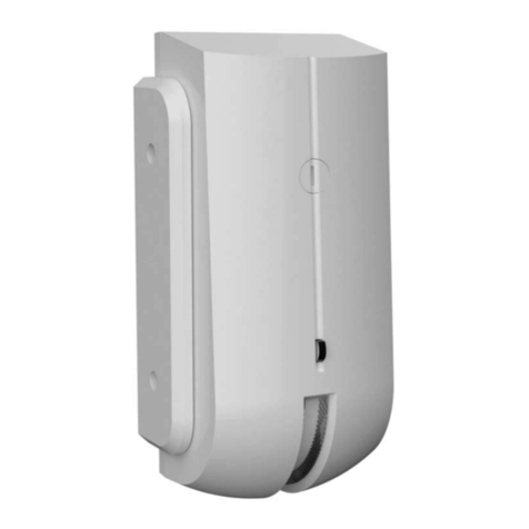
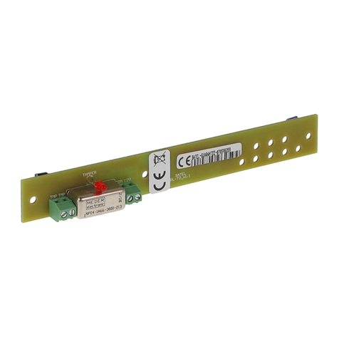
Satel XD-2 User manual

XD-2
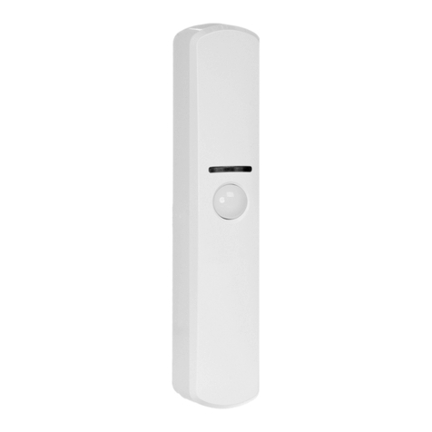
Multipurpose detector
EN
Firmware version 1.00 xd-2_en 05/21
SATEL sp. z o.o. •ul. Budowlanych 66 • 80-298 Gdańsk • POLAND
tel. +48 58 320 94 00
www.satel.eu

IMPORTANT
The device should be installed by qualified personnel.
Prior to installation, please read carefully this manual.
Changes, modifications or repairs not authorized by the manufacturer shall void your rights
under the warranty.
The rating plate of the device is located on the enclosure base.
SATEL aims to continually improve the quality of its products, which may result in changes in
their technical specifications and software. Current information about the changes being
introduced is available on our website.
Please visit us at:
http://support.satel.eu
The declaration of conformity may be consulted at www.satel.eu/ce
The following symbols may be used in this manual:
- note;
- caution.

CONTENTS
1. Features ...........................................................................................................................2
2. Description........................................................................................................................2
Alarms ..............................................................................................................................2
Additional alarm output.....................................................................................................3
Supply voltage control ......................................................................................................3
LED indicator....................................................................................................................3
3. Electronics board..............................................................................................................4
4. Configuring the detector settings......................................................................................5
Selecting the detector type...............................................................................................5
Two output mode enable / disable....................................................................................5
LED enable / disable.........................................................................................................6
Configuring the shock detector settings............................................................................6
5. Installation ........................................................................................................................6
6. Detector test.....................................................................................................................9
7. Specifications ...................................................................................................................9

2 XD-2 SATEL
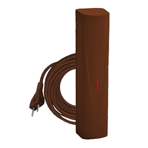
The XD-2 detector can work as:
magnetic contact,
shock detector,
shock detector and magnetic contact,
water flood detector.
This manual applies to the detector with firmware version 1.4.
1. Features
Detector type selected with DIP switches.
LED indicator.
Remote LED enable / disable.
Supply voltage control.
Tamper protection against enclosure opening and removal from mounting surface.
2 magnets included (for surface and flush mounting).
Magnetic contact
Detects open door, window, etc.
Input for connecting an NC type wired detector (e.g. other magnetic contact).
1 alarm output.
Shock detector
Detects shocks and vibrations accompanying attempts to force open a door or window.
Input for connecting an NC type wired detector (e.g. other magnetic contact).
1 alarm output.
Shock detector and magnetic contact
Detects shocks and vibrations accompanying attempts to force open a door or window.
Detects open door, window, etc.
Input for connecting an NC type wired detector (e.g. other magnetic contact).
1 or 2 alarm outputs.
Water flood detector
Detects flooding in spaces provided with plumbing systems.
1 alarm output.
Flood probe is not included with the detector. The FPX-1 probe is offered by SATEL.
2. Description
Alarms
Opening the tamper switch will turn on the tamper output (tamper alarm). The circumstances
in which the alarm output will open depend on the detector type.

SATEL XD-2 3
Magnetic contact
Alarm output will turn on after:
moving the magnet away from the detector (opening the window or door),
opening the SNS input.
Shock detector
Alarm output will turn on after:
detecting a shock caused by a single strong impact,
detecting a defined number of minor shocks caused by a series of light impacts,
opening the SNS input.
Shock detector and magnetic contact
Alarm output will turn on after:
detecting a shock caused by a single strong impact,
detecting a defined number of minor shocks caused by a series of slight impacts,
moving the magnet away from the detector (opening the window or door),
opening the SNS input.
Water flood detector
The alarm output will turn on approximately 1 second after the water level reaches the height
at which the probe contacts are installed. The alarm output will turn off a few seconds after
the water level drops below the height at which the probe contacts are installed.
Additional alarm output
When the detector works as a shock detector and magnetic contact, you can use 1 or 2
alarm outputs. If you enable the two output mode:
the NC output will indicate alarms from the magnetic sensor and the SNS input,
the S output will indicate alarms from the shock sensor.
When the two output mode is disabled, all alarms will be indicated by the NC output.
You can enable / disable the two output mode by using the DIP switch (see: “Two output
mode enable / disable”).
Supply voltage control
If the voltage drops below 9 V (±5%) for more than 2 seconds, the detector will signal
a trouble condition. When the trouble condition is present, the NC alarm output and the LED
indicator are ON. If the two output mode is enabled in the shock detector and magnetic
contact, the trouble condition is indicated by the NC and S outputs. The trouble is indicated
for as long as the condition is present.
LED indicator
The red LED indicates:
minor shock detected (does not reach the sensitivity threshold) –short flash,
alarm triggered by a shock –ON for 2 seconds,
alarm triggered by opening the window or door / opening the SNS input / detecting water
flooding –ON for as long as the condition that triggered the alarm is present,
trouble –ON for as long as the trouble condition is present.
4 XD-2 SATEL
The LED is also used during configuration of the shock detector (see: “Configuring the shock
detector settings”).
You can enable / disable the LED. When disabled, the LED will not indicate the events
described above, except for the trouble condition.
Enabling the LED with a DIP switch
If you enable the LED with a DIP switch (by setting the switch to LED position), the LED will
indicate events but remote LED enable / disable will be impossible. Disable the LED with the
switch if you want to enable / disable the LED remotely.
Remote LED enable / disable
The LED terminal is provided to allow remote LED enable / disable. When the terminal is
connected to common ground, the LED is enabled. When the terminal is disconnected from
common ground, the LED is disabled.
If the detector is used in the INTEGRA / INTEGRA Plus alarm system, you can connect to
the terminal an OC type control panel output programmed e.g. as “Zone test status” or “BI
switch”.
3. Electronics board
Do not remove the electronics board from the enclosure to avoid damage to the
components on the board.
potentiometers for configuring the shock detector (see: “Configuring the shock detector
settings”).
DIP switches for configuring the detector (see: “Configuring the detector settings”).
terminals:
SNS - input for connecting an NC type detector (e.g. magnetic contact) or a flood
probe. Cable length may not exceed 3 m. If no detector or flood probe is
connected to the input, the terminal must be connected to common ground.
LED - enable / disable the LED indicator.
S - alarm output (NC relay) used when the two output mode is enabled (see: “Two
output mode enable / disable”).
NC - alarm output (NC relay).
TMP - tamper output (NC).
COM- common ground.
+12V - power input.

SATEL XD-2 5
tamper switch activated by enclosure opening and removal from mounting surface.
The LED is located on the other side of the electronics board.
4. Configuring the detector settings
Selecting the detector type
Detector type
Switch setting
Magnetic contact
Shock detector
Shock detector and
magnetic contact
Water flood detector
Two output mode enable / disable
Two output mode
Switch setting
Disabled
Enabled

6 XD-2 SATEL
LED enable / disable
LED
Switch setting
Disabled
Enabled
Configuring the shock detector settings
Use the “SENS.” potentiometer to set the sensitivity of the shock detector (Fig. 2). When
a single shock is registered and it reaches the sensitivity threshold, alarm will be triggered.
Use the “SHKS NO.”potentiometer to set the number of shocks that will trigger alarm if they
are registered within 30 seconds (Fig. 2). The shocks do not need to reach the sensitivity
threshold. You can set 0-7 shocks. If you set 0, alarm will be triggered only by a shock that
reached the sensitivity threshold. After the settings are changed, the new value will be
demonstrated by the LED (the number of flashes corresponds to the number of shocks).
The sensitivity and the number of shocks are analyzed independently. Alarm will be
triggered by a single strong shock caused by a hard impact, or several minor shocks
caused by a series of light impacts.
5. Installation
Disconnect power before making any electrical connections.
The detector is designed for indoor installation. Consider the detector type when selecting the
place of installation. Mount the magnetic contact on a fixed surface (window / door frame)
and the magnet on a moving surface (window / door). When selecting the place of installation
for the shock detector, remember that its detection range depends on the type of mounting
surface. Mounting the detector on ferromagnetic surfaces or near strong magnetic and
electrical fields is not advisable, because it can result in malfunction of the detector.

SATEL XD-2 7
If the detector is to be installed on the window frame, select the upper part of the frame
for this purpose. This will reduce the probability of the detector being flooded by
accident, when the window is partially or fully open.
Prepare the cables for making connections and run them to the location where the device will
be installed. The cabling should not be run in close vicinity of low-voltage electrical system
wires, and especially of power wires for high-power equipment (such as electric motors).
You will need the following tools to mount the detector:
blade screwdriver 1.8 mm,
Philips screwdriver,
precision pliers,
drill with a set of drill bits.
1. Open the detector enclosure (Fig. 3). The enclosure opening tool, shown in the
illustration, is delivered with the detector.
2. Configure the detector (see: “Configuring the detector settings”).
3. Make the opening for cable in the enclosure base.
4. Run the cable through the opening (Fig. 4).
5. Using wall plugs (anchors) and screws, secure the enclosure base to the mounting
surface (Fig. 4). The wall plugs delivered with the device are intended for concrete, brick,
etc. For other types of surface (drywall, styrofoam), use the appropriately selected wall
plugs.
6. Place the cable in the enclosure base as shown in Fig. 4.
7. Connect the wires to the appropriate terminals.

8 XD-2 SATEL
8. Close the detector enclosure.
9. For the magnetic contact, install the magnet (Fig. 5), taking into account the maximum
permissible distance from the magnetic sensor (Fig. 6 and 7). The shown distance applies
to the magnet located at the height of the sensor. Location of the sensor in the enclosure
is shown in Fig. 8.
10.Power up the detector.
11.Test the detector (see: “Detector test”).
12.For the water flood detector, when the test is done, install the FPX-1 probe as shown in
Fig. 9. Install the probe just above the floor.

SATEL XD-2 9
6. Detector test
Make sure the LED is enabled, before you test the detector.
Check if the LED turns ON:
magnetic contact: after moving the magnet away from the detector (opening the window
or door),
shock detector: after impact against the surface protected by the detector,
The shock detector range depends on the type of surface on which the detector is
installed. The specified detection range (up to 3 m) should be considered an
approximate value. The actual detection range should be tested.
water flood detector: after submerging the flood probe contacts in water.
If a detector is connected to the SNS input, check if the LED on the XD-2 detector will turn
ON when that detector is violated.
7. Specifications
Supply voltage .................................................................................................... 12 VDC
±
25%
Standby current consumption.......................................................................................12.5 mA
Maximum current consumption........................................................................................14 mA
Outputs
NC alarm (NC relay, resistive load).............................................................40 mA / 24 VDC
S alarm (NC relay, resistive load)................................................................40 mA / 24 VDC
tamper (NC)................................................................................................. 40 mA / 24 VDC
Relay contact resistance
NC alarm output ............................................................................................................ 26 Ω

10 XD-2 SATEL
S alarm output ...............................................................................................................26 Ω
SNS input sensitivity:
NC type detector........................................................................................................150 ms
flood probe........................................................................................................................1 s
Complied with standards.......................EN 50130-4, EN 50130-5, EN 50131-1, EN 50131-2-6
Security grade according to EN 50131-2-6...................................................................Grade 2
Environmental class according to EN 50130-5 ........................................................................II
Operating temperature range...............................................................................-10°C...+55°C
Maximum humidity..........................................................................................................93
±
3%
Enclosure dimensions................................................................................... 20 x 102 x 23 mm
Surface mounted magnet enclosure dimensions.............................................. 15 x 52 x 6 mm
Surface mounted magnet spacer dimensions................................................... 15 x 52 x 6 mm
Flush mounted magnet enclosure dimensions......................................................ø10 x 28 mm
Weight.................................................................................................................................46 g
Magnetic contact
Gap (max.):
surface magnet ..............................................................................................20 mm
flush magnet...................................................................................................18 mm
Shock detector
Detection range (depending on the surface type).......................................................up to 3 m
Table of contents
Other Satel Security Sensor manuals

Satel
Satel ASD-100 User manual

Satel
Satel AQUA PRO User manual

Satel
Satel COBALT User manual

Satel
Satel AQUA RING S User manual

Satel
Satel AQUA PET User manual

Satel
Satel APMD-150 User manual

Satel
Satel SILVER User manual

Satel
Satel COBALT User manual

Satel
Satel FD-1 User manual

Satel
Satel AMD-101 User manual

Satel
Satel ARD-100 User manual

Satel
Satel AXD-200-DG User manual

Satel
Satel AQUA Series User manual

Satel
Satel MGD-300 User manual

Satel
Satel AGD-100 User manual

Satel
Satel FD-1 User manual

Satel
Satel GRAPHITE User manual

Satel
Satel PDB-100 User manual

Satel
Satel ACTIVA-2 User manual

Satel
Satel GREY User manual