2 ASD-100 SATEL
1. Installation
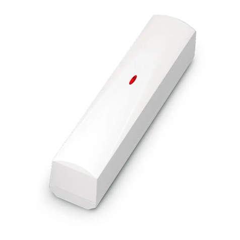
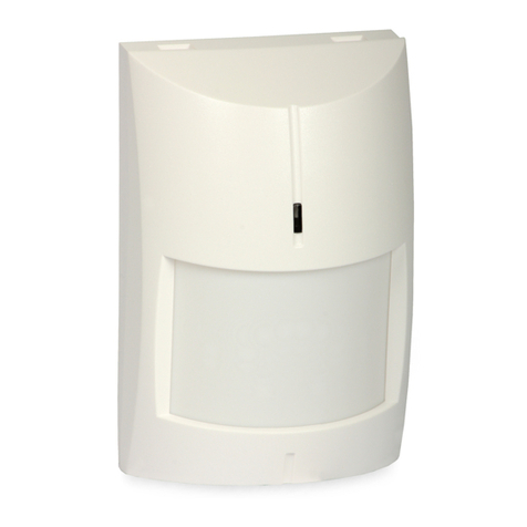
The detector is designed for indoor installation. It should be mounted on the ceiling, at least
0,5 m away from the walls.
Before mounting the detector permanently, check the level of signal received by
the ACU-100 controller from the detector and, if necessary, change the place of
installation so as to select the optimum location in terms of communication.
Install the battery inside the detector just before registering it in the controller. If
unregistered or having no communication with the controller, the detector will
consume more energy, which will reduce the battery life.
Do not install the detector in places with high concentration of dust and/or
formation and condensation of water steam. The detector should not be
mounted in the vicinity of heaters and cookers.
1. Open the housing, turning the cover anticlockwise.
2. Install the battery and add the detector to the wireless system (see the ACU-100 controller
user manual). A label with 7-digit serial number that should be entered during registration of
the detector in the system is provided on the electronics board.
3. Close the housing. Put the cover where the electronics board and the optical chamber are
installed to the base as shown in Fig. 1: the indices on the edges of base and cover must
be aligned. Turn the cover clockwise.
4. Select the place where the detector is to be installed and attach it there temporarily.
5. Check the level of signal reaching the controller from the detector. If necessary, select
another place for installation.
6. Having selected the place which ensures the optimum signal level, open the housing and
secure the housing base to the ceiling.
7. Close the detector housing.
8. Configure the detector as required. For configuration information see the ACU-100
controller user manual. When the configuration is finished, the detector is ready for work.
2. Maintenance
The ASD-100 detector requires periodic checks which should be carried out at least every 6
months. With the passage of time, accumulation of dust inside the optical chamber may
result in false alarms being reported by the detector. In order to check the status of optical
chamber, run remotely the test mode and watch how the LED indicator is flashing in the
detector during polling. When the optical chamber is fouled, the LED indicator flashes 2 times
(normally, the polling period is signaled by a single flash).
Note: When the LED indicates alarm memory by flashing, there is no signaling of
communication with the controller.
When the LED indicates fouling of the chamber, do the following:
1. Open the detector housing.
2. Release catches in the housing and remove the electronics board with optical chamber .
3. Remove the optical chamber cover.
4. Using a soft brush or compressed air, clean the cover labyrinth and the optical chamber
base, paying attention to the recesses where LEDs are situated.
5. Replace the optical chamber cover.
6. Secure the electronics board with optical chamber in the cover catches. The electronics
board must be fastened so that the LED can contact the optical cable.
