SATO D508 User manual

PN: 9001178
D508/D512
PRINTER
SERVICE MANUAL

PN: 9001178
SATO America, Inc.
10350A Nations Ford Road
Charlotte, NC 28273
Main Phone: (704) 644.1650
Technical Support: (704) 644.1660
Technical Support Fax: (704) 644.1661
E-Mail: satosale[email protected]
techsupport@satoamerica.com
www.satoamerica.com

PN: 9001178
Table of Contents
Overview
Introduction ........................................................................................................................................... 1-3
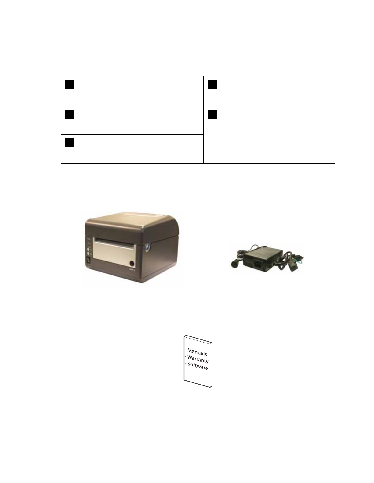
Unpacking ............................................................................................................................................. 1-4
Printer Part Names ............................................................................................................................... 1-5
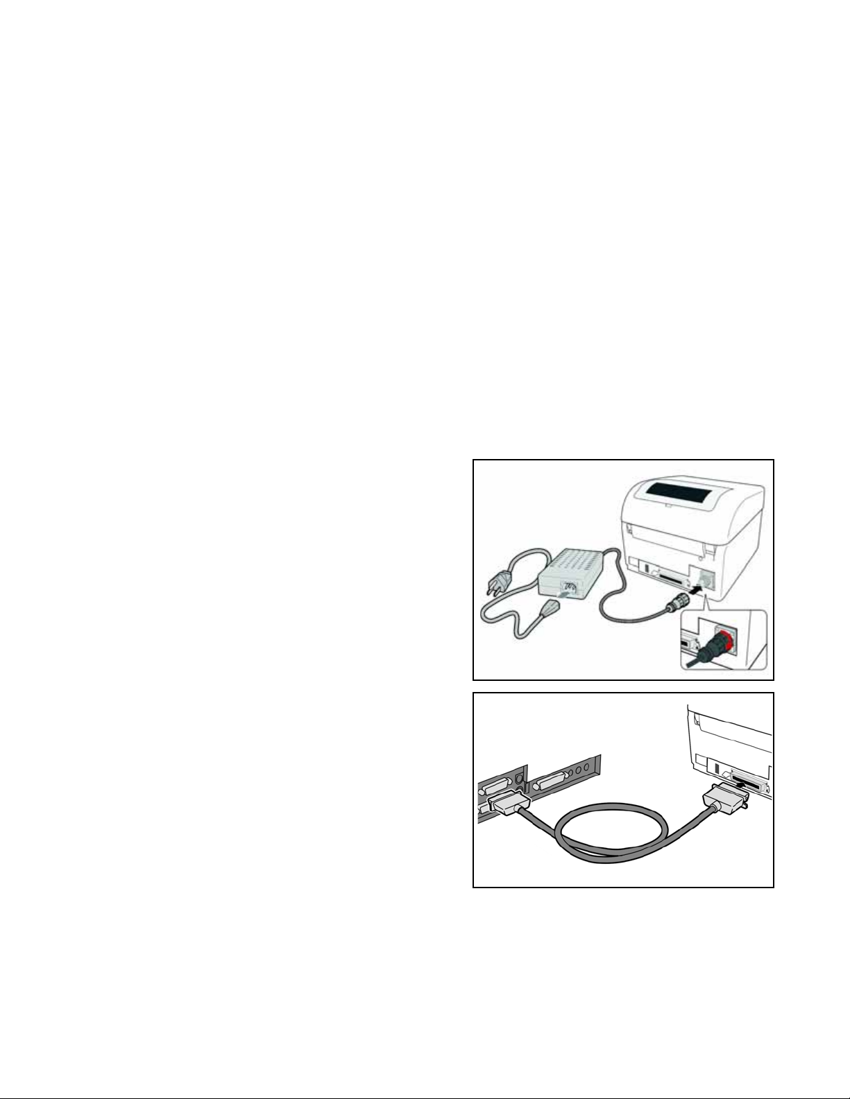
Setting Up The Printer .......................................................................................................................... 1-6
Loading Media ...................................................................................................................................... 1-7
Label Sensing ....................................................................................................................................... 1-9
3.1 Operating Panel ............................................................................................................................ 1-10
Configuration: The Rear Panel ........................................................................................................... 1-11
The Configuration Panel ..................................................................................................................... 1-12
Switch 4: Unused ................................................................................................................................ 1-13
Switch 5: Head Check ........................................................................................................................ 1-13
Switch 6: VR1 Potentiometer Adjustment mode ................................................................................. 1-13
Offsets ................................................................................................................................................ 1-15
Potentiometer Adjustments ................................................................................................................. 1-16
Data Dump Diagnostic Label .............................................................................................................. 1-18
Printing Test Labels ............................................................................................................................ 1-19
Printing Factory/Service Test Prints ................................................................................................... 1-20
Basic and Interface Specifications
1.1 Basic Printer Specifications .......................................................................................................... 2-2
1.1 General Specifications (cont’d) ...................................................................................................... 2-3
Interface types ...................................................................................................................................... 2-6
The Receive Buffer ............................................................................................................................... 2-7
IEEE1284 Parallel Interface .................................................................................................................. 2-9
RS-232C Interface .............................................................................................................................. 2-10
RS-232C Interface Signals ................................................................................................................. 2-11
Universal Serial Bus Interface ............................................................................................................ 2-12
Local Area Network Interface ............................................................................................................. 2-13
Wireless 802.11 LAN Interface ........................................................................................................... 2-13
Troubleshooting
Interface Troubleshooting ..................................................................................................................... 3-5
Troubleshooting Flowcharts .................................................................................................................. 3-7
Problem: Printer Does Not Power Up ................................................................................................... 3-7
Problem: Label Does Not Feed Outward In A Straight Path ................................................................. 3-8
Problem: Printer Does Not Print ........................................................................................................... 3-8
Problem: Printer Does Not Print ........................................................................................................... 3-9
Problem: Printer Does Not Feed Labels ............................................................................................. 3-10
Problem: Printer Does Not Stop At The Correct Position ................................................................... 3-11
Problem: Wireless LAN Printer Is Not Printing ................................................................................... 3-11
Problem: Printing Is Too Dark ............................................................................................................. 3-12
Problem: Printing is Too Light On One Side ....................................................................................... 3-12

Problem: Print Start Position Is Incorrect Vertically ............................................................................ 3-13
Problem: Print Start Position Is Incorrect Horizontally ........................................................................3-14
Problem: White Lines Appear In Printed Labels ................................................................................3-14
Problem: Labels are Not Being Dispensed Properly By The Optional Dispenser Unit ...................... 3-15
Problem: The Cutter Is Not Working ................................................................................................... 3-16
Test Print Troubleshooting .................................................................................................................. 3-17
Test Labels ......................................................................................................................................... 3-17
Data Dump Diagnostic Label .............................................................................................................. 3-19
Printing Factory/Service Test Labels .................................................................................................. 3-20
Replacement Procedures
Print Head Replacement ....................................................................................................................... 4-2
Platen Roller Replacement ................................................................................................................... 4-3
Accessing the Main Board .................................................................................................................... 4-4
Fuse Replacement ................................................................................................................................ 4-5
Main Circuit Board Replacement .......................................................................................................... 4-6
Panel Board Replacement .................................................................................................................... 4-7
Relay Board (Label Sensor Board) Replacement ................................................................................. 4-8
Label Sensor Replacement ................................................................................................................ 4-10
Cover Sensor Replacement ................................................................................................................ 4-12
Drive Motor Replacement ................................................................................................................... 4-14
Drive Gear Replacement .................................................................................................................... 4-16
Cutter Assembly ................................................................................................................................. 4-18
Checks/Adjustment Procedures
Top of Forms Offset .............................................................................................................................. 5-2
Factory Clear ........................................................................................................................................ 5-3
Print Darkness ...................................................................................................................................... 5-4
Printer Counter Clear ............................................................................................................................ 5-6
Cutter Counter Clear (If Cutter Is Installed) .......................................................................................... 5-6
Test Print Counter Clear ....................................................................................................................... 5-7
Cut Position (If Cutter Is Installed) ........................................................................................................ 5-7
Eye Mark / Paper End Sensor Sensitivity ............................................................................................. 5-8
Paper End Sensor Sensitivity (Alternate) ............................................................................................. 5-8
Gap Sensor Sensitivity ......................................................................................................................... 5-9
Gap Sensor Sensitivity (Alternate) ........................................................................................................ 5-9
Power Supply Checks ......................................................................................................................... 5-10

Unit 1: Overview
SATO D508/D512 Service Manual Page 1-1
OVERVIEW

Page 1-2 SATO D508/D512 Service Manual
OVERVIEW
Thank you for your investment in this SATO printer product.
This Service Manual contains information about the specifications, replacement procedures,
checking/calibration procedures, and troubleshooting of common problems associate with the
D508/D512. A total of four topics are covered herein, and they are organized as follows:
Section 1: Overview
Section 2: Basic and Interface Specifications
Section 3: Troubleshooting
Section 4: Replacement Procedures
Section 5: Checks and Adjustment Procedures
The Overview section provides a description of the printer, information on how to access the
main board, how to unpack the printer, how to identify the printer parts, how to set up the printer,
how to load media, information on label sensing and configuration, adjustments, and test labels.
The Basic and Interface Specifications section serves as a guide to personnel who need to
understand the communication protocols needed to control the printer using third party software,
and for troubleshooting interface problems.
The Troubleshooting section aids in the process of diagnosing and correcting common prob-
lems. After troubleshooting, the service personnel can then determine whether any repairs, parts
replacements and/or adjustments are necessary,
The Replacement Procedures section covers the main components of the product, and how the
service personnel can dismantle and reassemble the parts in order to maintain, clean, repair or
replace them.
Finally, the Checks and Adjustment Procedures are needed after certain maintenance or
repair work involving certain precision components.
It is recommended that you become familiar with each section before attempting to service the
product. Refer to the Table Of Contents at the front of this manual to search for the relevant
information needed. All page numbers in this manual consist of a section number followed by the
page number within the stated section.
Note:
All information herein was correct and current at the time of publication. The contents of this doc-
ument are subject to revision and change without prior notification to users. To obtain the most
current version of this document, refer to the SATO website at www.SATOAmerica.com.

Unit 1: Overview
SATO D508/D512 Service Manual Page 1-3
INTRODUCTION
The SATO D508/D512 Printer Service Manual provides information for installing and maintaining
D508/D512 Direct Thermal printers. Step-by-step maintenance instructions are included in this
manual with typical problems and solutions. It is recommended that you become familiar with
each section in this manual before installing and maintaining the printer.
The major difference in the D508 and the D512 printers is the resolution of the print head. The
D508 with its 203 dpi head provides an economical labeling solution for most applications. It can
print labels up to four inches wide. The D512's higher 305 dpi resolution provides greater detail
for graphics and small point size text.
The D5 Series printers use a subset of the standard SATO Command Language. The D508 and
D512 share the same command set, the only differences are the allowable values representing
the print positions on the label. These values are specified in "dots" and will vary depending upon
the resolution of the printer and the amount of memory available for imaging the label. The allow-
able range for each printer is specified in a table for those command codes. In addition, users
can choose an interface—such as parallel (IEEE1284), serial (RS-232C), Ethernet (10/100-
BaseT), USB 1.1and Wireless LAN IEEE 802.11b.

Unit 1: Overview
SATO D508/D512 Service Manual Page 1-4
UNPACKING
When unpacking the printer, take note of the following:
Note:
The following parts shown here are representative only. Due to regional requirements and our policy of
continual improvement, your printer may not be packed with the exact parts as shown here, but the
unpacking steps are similar.
The box should stay right-side up.
Lift the printer out of the box carefully.
If the printer has been stored in the
cold, allow it to reach room
temperature before turning it on.
Remove the plastic covering from the
printer.
Set the printer on a solid, flat surface.
Inspect the shipping container and
printer for any sign of damage that
may have occurred during shipping.
Remove the accessory items from their
protective containers.
1
4
2
5
3
Printer AC adaptor and cable
User documentation and software
package (where applicable)

Page 1-5 SATO D508/D512 Service Manual
PRINTER PART NAMES
Clear window and
fanfold-label Loading
Top Cover
Label Outlet
Front cover
(allows access to optional cutter unit, DIP switches
and potentiometers)
LINE/FEED/
Power
buttons and
LEDs
7-segment
Error Status LED
Release latch for Top Cover
Mini
Screwdriver
Label Holders
Thermal Print
Head assembly
Label Holder Release Knob
Platen Assembly
Label Sensor
Optional Cutter

Unit 1: Overview
SATO D508/D512 Service Manual Page 1-6
SETTING UP THE PRINTER
Consider the following when setting up the printer:
Locate a solid flat surface with adequate room to set the printer. Make sure the AC
adaptor can be located so that the AC power cable can be attached to the printer and
an AC power outlet. The location should be near the host or computer terminal. The
maximum distance recommended is:
- 10 feet for a Parallel interface cable. Make sure it meets IEEE1284 specifications
- 18 feet for the optional Serial RS232 Interface
- 10 feet for the optional USB interface without hub
- the optional 10baseT Ethernet Interface depends upon the LAN cabling
- Up to 100m for the Wireless LAN, depending on structural conditions
Follow these steps to set up your printer:
1. Make sure the power switch on the Operator
Panel is in the OFF (0) position and place the
AC adaptor in a safe and secure location.
2. Connect the Input Power connector to the
printer. This connector is buttoned and must
be turned approximately 3/4 turn clockwise to
secure it to the printer.
3. Connect the AC Power Cable to an AC Outlet
supply of an appropriate voltage.
4. Connect the interface cable to the host system.
If you are using the Parallel Port connection, a
parallel IEEE1284 interface cable must be
used to realize the high data transfer rate of
the printer's parallel port. If another interface is
installed, the appropriate cable should be
used.
5. Load the label media following the instructions
in this section.
6. Configure the printer for label width and operating mode using the instructions in this section.
7. Press the printer power button to the ON (I) position.
8. Print a test label to verify the printer is set up and operating correctly.

Page 1-7 SATO D508/D512 Service Manual
LOADING MEDIA
The SATO D508/D512 printer can print to direct thermal die-cut labels, tags or continuous media.
The media supply can be either in Roll or Fanfold format.
Roll Media
Roll media should be between 0.98" (25 mm) and 4.3" (110 mm) in width and wound face-out on
a core with a minimum internal diameter of 1.6" (40 mm).
1. Make sure the printer is turned OFF.
2. Open the Top Cover by pressing on cover
release points located on the right-hand
side of the printer. This releases the Top
Cover and allows it to swing upward on the
rear mounted hinge points.
3. With the Top Cover in the upright position,
press the Paper Guide Release while
adjusting the Paper Guides until they allow
a media roll to fit between them. A millime-
ter scale is molded into the case to provide
a guide when making the adjustment. The
Paper Guides are center justified and inter-
act with each other so that each moves an
equal distance.
4. Make sure the Roll Holders are in the
released position. If they are not, lift up on
each one and they will snap to the open
position.
5. Unwind approximately 12" of label material
from the roll. The labels should be wound
face-out (printing side to the outside of the
roll). Drop the roll in-between the Paper
Guides so that the labels come off the top
of the roll. The Paper Guides will automati-
cally position the Roll Holders to suspend
the roll.
Cover/Print Head
Release Latch
Roll Holders
Paper
Sensor
Millimeter
scale
Paper Guide
Release
Label path

Unit 1: Overview
SATO D508/D512 Service Manual Page 1-8
6. Route the label material through the Paper
Sensor Assembly and over the Platen. Note
that the Sensor is part of the left Label Roll
Guide so that the Paper Sensor is always
positioned in the same location relative to
the left edge of the label.
7. Close the Top Cover.
8. Press the LINE button so that the printer is
in the OFF LINE mode and then press the
FEED button. The label should advance to
the next index (label gap) position.
Fanfold media
1. Place the fanfold media behind the printer
with the printing surface up.
2. Open the Top Cover by pressing on the cover
release latch located on the right-hand side
of the printer. This releases the cover and
allows it to swing upward on the rear
mounted hinge points.
3. Carefully pull up the Fanfold-label Loading
Slot from the back of the Top Cover.
4. With the Top Cover in the upright position,
press the Paper Guide Release while adjust-
ing the Paper Guides until they allow a media
to fit between them. A millimeter scale is
molded into the case to provide a guide when
making the adjustment. The Paper Guides
are center-justified and interact with each
other so that each moves an equal distance
apart from each other.
5. Route the label material through the Sensor
Assembly and over the Platen.
Paper Sensor Paper Guide
Platen
Pull up
the
loading
slot
Pull
open
the Top
Cover
Load
the
fanfold
paper

Page 1-9 SATO D508/D512 Service Manual
6. Close the Top Cover.
7. After loading the label media, it is
recommended that you run a Test
Print to make sure the labels are
correctly loaded and printed.
LABEL SENSING
The SATO D508/D512 uses label Gap (see-through) or Eye-Mark (reflective) sensing. The
Sensor Assembly is located on the left edge of the media and is automatically positioned by the
Paper Guides.
Fanfold-label path
Roll-label path
Overview of the fanfold-paper loading path

Unit 1: Overview
SATO D508/D512 Service Manual Page 1-10
CONFIGURATION
Before using the printer, it is best to read this manual thoroughly first. Otherwise, you may disturb
default settings around which the instructional procedures in this manual are based upon.
3.1 OPERATING PANEL
The Operator Panel consists of three LED indicators and three switches.
POWER
The green LED lights up when the printer is ON.
ERROR
The red LED lights up when there is a system fault
such as an unlatched print head.
ON LINE
The green LED lights up when the printer is ON LINE
and ready to receive data. The ON LINE button
takes the printer ONLINE or OFFLINE.
LINE Button
If the ONLINE LED is lit, pressing it will take the printer
OFFLINE. Pressing the button again then takes the printer
back ONLINE. When ONLINE, the printer is ready to
receive data from the host. When OFFLINE, the printer
will not print or accept data from the host. While the
printer is printing, press this button to suspend the
printing. To resume printing, press this button again.
FEED BUTTON
Press this button to eject one label in OFFLINE mode.
Hold this button down while power is applied, to print a printer
status label.
POWER SWITCH
A two position switch for turning the printer ON (I) or OFF (0).

Page 1-11 SATO D508/D512 Service Manual
CONFIGURATION: THE REAR PANEL
All of the printer cable connectors are located on the Rear Panel, as follows.
Fanfold-label Loading Slot
Remove this panel to route fanfold paper into the printer
Power
Connector
for DC power
input from the
supplied AC
Adapter
Interface
Slot
(IEEE1284
Parallel
Interface
Connector
shown)

Unit 1: Overview
SATO D508/D512 Service Manual Page 1-12
THE CONFIGURATION PANEL
The Configuration Panel is accessible when you lift up the top cover.
The panel consists of an eight-position DIP switch, four adjustment potentiometers and a seven-
segment LED Error Status display. Receptacles for connecting the optional Cutter (factory
installed) are also located on this panel.
DIP SWITCH SETTINGS
This is an eight-position switch used for setting the operating conditions of the printer. Switches 1
to 3 act as control for both paper handling and the loading of programs or fonts into the printer.
Switches 1–3: Paper Handling settings
These three switches select the method used for
controlling paper handling:
Continuous mode - (default mode) Does not
use the sensor for paper indexing. The paper
movement will stop after all the label data has
been printed.
Tear Off mode - Paper is fed out to the cut/tear
off position after printing is complete. Before the
next label is printed, the paper is pulled back in
to the first print line position.
Cutter mode - Enables the Cutter option if
installed.
Error
Status
LED
DIP switch for
Configuration
VR4
Label Pitch
Offset
VR2
EYE MARK
VR3
GAP
VR1
Offset or
Darkness
DSW1 DSW2 DSW3 Mode
Off Off Off Continuous
On Off Off Tear Off
Off On Off Cutter
On Off On Reserved
Off On On Load Font
Configuration Switch
ON
OFF
12345678

Page 1-13 SATO D508/D512 Service Manual
DIP SWITCH SETTINGS (CONT’D)
Switches 1–3: Font/Graphic loading settings
Enables the loading of fonts and/or graphics into
printer memory for faster retrieval.
Switch 4: Unused
This switch is reserved for future use.
Switch 5: Head Check
Enables or Disables the printer function that checks
the print head automatically.
Switch 6: VR1 Potentiometer Adjustment mode
Selects the function adjusted by VR1. When placed
in the OFF position, VR1 will adjust the media tear-
off / cut (backfeed distance) offset value over a
range of +/- 3.75 mm. When placed in the ON
position, VR1 will adjust the print darkness range.
DSW1 DSW2 DSW3 Mode
Off On On Load Font
Configuration Switch
ON
OFF
12345678
DSW4 Mode
Off DT
On Reserved
Configuration Switch
ON
OFF
12345678
DSW5 Mode
Off Disabled
On Enabled
Configuration Switch
ON
OFF
12345678
DSW6 Mode
Off Media Tear-Off
On Print Darkness
Configuration Switch
ON
OFF
12345678

Unit 1: Overview
SATO D508/D512 Service Manual Page 1-14
DIP SWITCH SETTINGS (CONT’D)
Switch 7: DATA Dump
When ON, the printer will print out the hex value for
each character received. When OFF, the printer will
accept and process the data stream in a normal
fashion.
Switch 8: Unused
This switch is reserved for future use.
DSW7 Mode
Off Disabled
On Enabled
Configuration Switch
ON
OFF
12345678
DSW8 Mode
--
--
Configuration Switch
ON
OFF
12345678

Page 1-15 SATO D508/D512 Service Manual
OFFSETS
There are two offset settings stored in the printer; one for the Cut mode and one for the Tear-Off
mode.
These two offsets can be set independently and will remain in the printer until a new command is
received changing the setting or until power is turned off.
The default settings can be determined by printing a User Test Label.
The following should be used as starting points for establishing the three Offset values:
Mode Length of Offset (mm) Length of Offset (in) Print head resolution
CUTTER 17.9 0.70 143/215
TEAR-OFF 29.2 1.15 234/350

Unit 1: Overview
SATO D508/D512 Service Manual Page 1-16
POTENTIOMETER ADJUSTMENTS
PITCH OFFSET
This can be done using the VR4 potentiometer on the Configuration Panel. This potentiometer is
set at the factory so that it has a range of +/-3.75 mm. The midpoint setting should have no effect
on the label pitch. Turning the potentiometer all the way clockwise should move the print position
3.75 mm upwards towards the leading edge of the label. Turning the it all the way
counterclockwise should move the print position down 3.75mm away from the leading edge of
the label.
1. Place DSW6 on the Configuration Switch in
the OFF position.
2. Turn the power OFF.
3. While pressing the FEED button on the
Operator Panel, turn the power ON.
4. When you hear one beep from the printer,
release the FEED button.
5. Press the LINE button to begin printing
large Test Labels (press the FEED button
if you are using labels smaller than 4.1"
(104 mm) in width).
6. Adjust potentiometer VR4 until the first
print position is at the desired location on
the label.
7. Press the FEED button to stop printing.
Note:
Adjusting the Label Pitch with VR4 will
affect the stop position of the label and the
cut/tear-off positions.
ABCDEFG
ABCDEFG
ABCDEFG
Leading Edge of
Label as detected
by the sensor
Moved with
Positive (+) Offset
to print on trailing
edge of label
Must be moved with Minus (-)
Offset to print on leading edge of
label
Original First Line
Print Position
label movement direction
Other manuals for D508
2
This manual suits for next models
1
Table of contents
Other SATO Printer manuals
Popular Printer manuals by other brands

Evolis
Evolis Elypso user guide

Lexmark
Lexmark 522n - C Color Laser Printer Service manual

Kyocera
Kyocera FS-9530DN specification

Epson
Epson R320 - Stylus Photo Color Inkjet Printer Product information

Roland
Roland SOLJET Pro III XC-540 Service notes

Canon
Canon iP5000 - PIXMA Color Inkjet Printer quick start guide

Brother
Brother QL-570VM - B/W Direct Thermal Printer user guide

Canon
Canon Pixma TS3400 Series Getting started

Epson
Epson WorkForce WF-M1030 Start here

Craind Impianti
Craind Impianti FT190S user manual

AMT Datasouth
AMT Datasouth Documax 5380 quick start guide

Toshiba
Toshiba TEC B-850 Series Key Operation Specification