TABLE OF CONTENTS
iii
2.3 Setting the AT10.1 parameters
2.3.1 Understanding parameter settings.................................................................30
2.3.2 Setting the Float and Equalize voltages.........................................................31
2.3.3 Setting the Equalize timer..............................................................................32
2.3.4 Setting the Alarms..........................................................................................32
Setting the high and low dc voltage alarms ...................................................33
Adjusting ground detection sensitivity............................................................34
Disabling the ground detection alarm ............................................................35
2.3.5 Setting the current limit value.........................................................................35
2.3.6 Enabling the high dc voltage shutdown feature.............................................36
2.3.7 Adjusting the Voltmeter accuracy ..................................................................37
2.3.8 Using the Low Level Detector (LLD)..............................................................38
2.3.9 Using the front panel security feature............................................................39
2.4 Performing routine maintenance ..........................................................................40
Sample preventive maintenance procedure.........................................................42
3Servicing the AT10.1 Battery Charger
3.1 A step-by-step troubleshooting procedure ...........................................................44
3.2 Interpreting front panel error messages ...............................................................45
3.3 Using the troubleshooting chart............................................................................48
3.4 Troubleshooting chart begins on..........................................................................49
3.5 Replacing defective components..........................................................................58
3.6 Ordering replacement parts..................................................................................62
Replacement parts tables (begin on)....................................................................62
APPENDIX A: AT10.1 Performance Specifications................................................................70
APPENDIX B: Field Installable Accessories...........................................................................71
APPENDIX C: Standard Drawings *
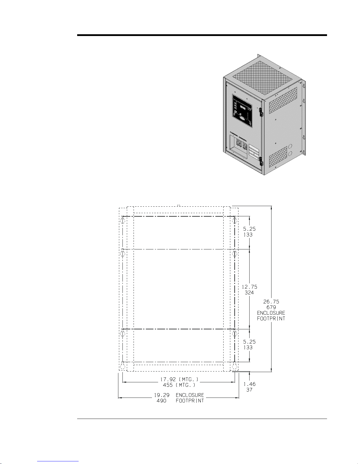
AT10.1 Series Battery Charger Outline: NEMA-1 Style-5017 Enclosure.....................................72
AT10.1 Series Battery Charger Outline: NEMA-1 Style-5018 Enclosure.....................................74
AT10.1 Series Battery Charger Internal Component Layout: Style-5017 Enclosure....................76
AT10.1 Series Battery Charger Internal Component Layout: Style-5018 Enclosure....................78
AT10.1 Series Battery Charger Instrument Panel / PC Board Detail...........................................80
Schematic -AT10.1 Group II Battery Charger -Standard w/o Options........................................82
Schematic -AT10.1 Group II Battery Charger -with Common Options.......................................84
Connection Diagram -AT10.1 Group II Battery Charger -Standard w/o Options........................86
Connection Diagram -AT10.1 Group II Battery Charger -with Common Options.......................88
Wire List -AT10.1 Group II Battery Charger................................................................................90
APPENDIX D: Recommended Float / Equalize Voltages.......................................................92
APPENDIX E: DNP3 Level 2 / Modbus Communications Module.........................................93
MANUAL SPECIFICATIONS (document control information / online availability) .....................94
* Note: A customized record drawing package is available for your AT10.1, featuring an itemized
internal component layout, electrical schematic with component ratings, and a full connection diagram.
If the standard drawings and wire list featured in this manual are not sufficient, please contact your Sales
Representative for drawing availability from the battery charger manufacturer.