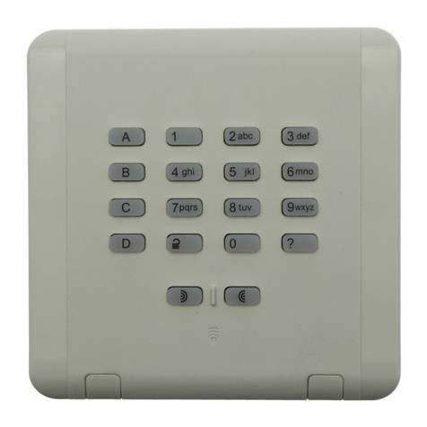
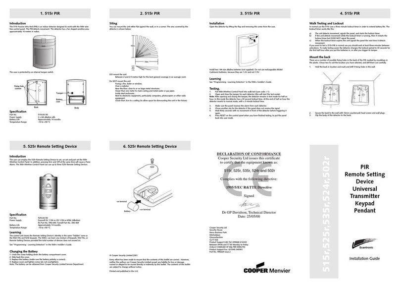
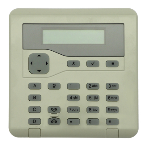
Scantronic KEY-RAS User manual

Scantronic
KEY-RAS
UK
Introduction
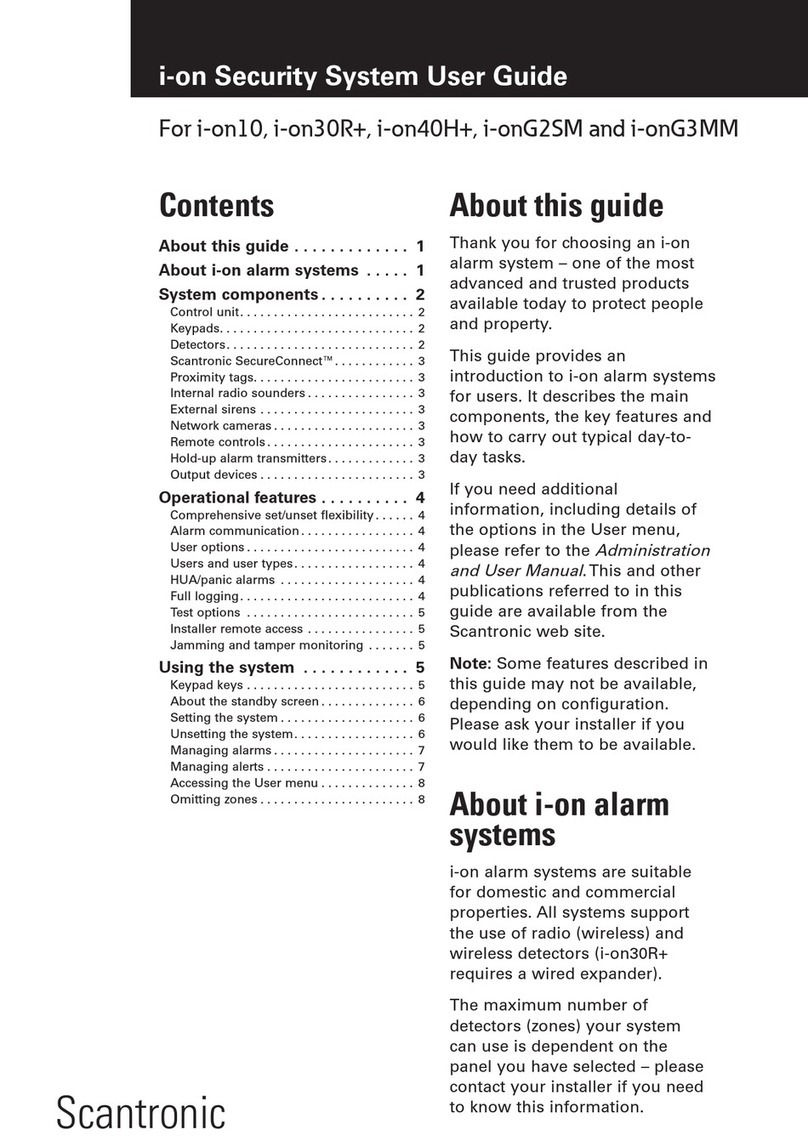
The KEY-RAS allows users to set, unset and
part-set the system, operate output devices,
and query the current set/unset status of the
system.
You can configure the KEY-RAS in either 2-way
or 1-way mode:
•
2-way mode provides full functionality and
is compatible with later-generation control
units (see
Specifications
). It enables the
KEY-RAS to display the current set or unset
status of the system, and to sound entry,
exit and alarm tones.
•
1-way mode gives backwards compatibility
with previous-generation i-rk01 arming
stations, and cannot feed back the current
status of the system or produce entry, exit
and alarm tones.
Note: When installed in a partitioned system,
the KEY-RAS can be used with only one
partition.
Features:
•
Used to set, unset or part set the system,
and operate output devices
•
Includes an internal proximity reader
•
1-way or 2-way mode available
•
Query key (operates for 2-way mode only)
•
Hold-Up Alarm (HUA) and programmable
ABCD keys
•
Battery powered, with optional connections
for an external supply
•
Cover and back tamper detection
•
Easy to install
•
Uses Rolling Code technology for enhanced
security
The control unit’s
Engineering Guide
specifies
the maximum number of devices you can
use (same as i-rk01).The
KEY-RAS User Guide
gives details about how to use the device.
This product must be installed and maintained
only by qualified service personnel.
External power supply
An optional 9-15Vdc external supply (not
provided) can be used to prolong battery
life.The batteries are used only if the supply
fails. Note: Batteries must be fitted, even if an
external supply is used.
Step 1: Choose the mounting
location
Locate the KEY-RAS out of sight of potential
intruders and within the area protected by the
intrusion system.
To ensure correct operation of the internal
proximity reader and radio transceiver, do not
locate the KEY-RAS:
•
Within 1 metre of another proximity reader
(including one located within a keypad).
•
In a metal enclosure.
•
Near to any source of electromagnetic or
radio interference.
•
Within 1 metre of high-voltage cables,
metal pipes, computers, photocopiers, or
other electronic equipment.
Check that the KEY-RAS will be within radio
range of the control unit or expander.You can
use theTest menu to check signal strength
(see below).
Step 2: Mount the backplate
1. Using a thumb (not a tool), flip down
the screw covers and remove the screws
(Figure 1).
2. Lift the cover upwards, off its hinges.
3. Mount the backplate to the wall (Figure 2).
Figure 1. Removing the cover
Cable-entry hole
(on each side)
Use the supplied 3mm x 19mm (No4)
screw for the tamper block
Minimum 3 off
4mm x 25mm (No8)
countersunk screws
for backplate
Figure 2. Mounting the backplate
Step 3: Congure the DIP
switches
Note: You must configure the DIP switches
before powering up the KEY-RAS.
The DIP switches are located on the PCB.
OFF
ABCD LEDs
TIMED
2 WAY
BACKLIGHT
BACKLIGHT BRIGHT
PROX
KEYPAD TONES
1 WAY
ON
Figure 3. DIP switches
UK KEY-RAS Radio Arming Station − Installation Instructions
DE KEY-RAS Funkaktivierungsstation − Installationsanweisungen
FR Clavier de commande radio KEY-RAS − Guide d’installation
IT KEY-RAS - Radio-stazione di inserimento − Istruzioni per l’installazione
NL KEY-RAS Draadloos inschakelpaneel − Installatiehandleiding
Proximity reader / Chip-Leser / Lecteur de proximité / Lettore di prossimità / Proximitiy lezer
ABCD LEDs (applicable only if the KEY-RAS is
powered externally) − If set to OFF (default for
battery operation), the ABCD LEDs switch off
10 seconds after the event that lit them. If set
to ON, the LEDs remain permanently lit.
BACKLIGHT (applicable only if the KEY-RAS
is powered externally) − If set to OFF (default
for battery operation), the LED backlights
switch off 10 seconds after the event that
lit them. If set to ON, the backlights remain
permanently lit.
BACKLIGHT BRIGHT − Set to ON to enable
full brightness for the backlight. Set to OFF for
reduced brightness.
PROX − Set to ON to enable the internal
proximity reader. Set to OFF to disable the
proximity reader.
KEYPAD TONES − Set to ON if you require a
tone each time a key is pressed. Set to OFF to
disable the tone.
2 WAY / 1 WAY − Select 1-way or 2-way mode.
Step 4: Power up the KEY-RAS
Remove the insulating tab from the battery
compartment. If applicable, connect the
external power supply to the terminals on the
PCB. Do not refit the front cover at this stage.
Step 5: Learn the KEY-RAS
1. From the control unit’s Installer menu,
select the option to add a radio keypad
(i-rk01 for 1-way mode, or KEY-RAS for
2-way mode).
2. Operate the tamper switch.You should see
confirmation at the control unit that the
device has been added.
3. Refit the front cover.
4. In the Installer menu, edit the radio keypad
to configure:
•
The partition that the KEY-RAS is to
control (partitioned mode only).
•
The action for each ABCD key: full set,
part set, or operate an output (of type
User Defined).
•
Battery Only − Choose Ye s if only a
battery is used, or No if an external PSU
is also used. Selecting Ye s prevents
an “RKU n PSU Fail” message, which
indicates loss of power supply.
•
Buzzer Volume − Choose the required
volume of the internal sounder.
Installation is now complete.
Note: Sounds from the KEY-RAS may start
and stop after a short delay. This is normal,
and is due to the nature of the radio
communications.
Programmable keys / ProgrammierbareTasten /Touches programmables /Tasti programmabili / Programmeerbare toetsen
Hold-up keys / Überfalltasten / Touches Agression / Tasti allarme panico / Overval-toetsen
1
Query key / Abfragetaste /Touche Requête /Tasto di richiesta stato / Vraag-toets

Page 2
Checking Signal Strength
After installing the KEY-RAS, you can check
signal strength using
Installer menu,Test,
Signal Strengths, Radio Keypads
.
A minimum reading of 2 is acceptable. (When
reading from the web interface or other
software, a minimum reading of 4 is needed if
the control unit is in User mode, or 2 if it is in
Installer mode.)
Maintenance
Each year, replace the batteries, perform an
annual test (using theTest menu at the control
unit), and clean the outside of the KEY-RAS
using a soft dry cloth. Do not use water,
solvents or any proprietary cleaning agents.
Specications
Compatibility for 2-way mode: i-on Compact
(v5.03.40 or higher), i-on Style (v5.02.40 or
higher).
Compatibility for 1-way mode: Any control
unit or expander that can operate with the
i-rk01 (e.g. i-on16, i-on40 and i-onEX), or does
not have updated firmware for 2-way mode.
Batteries: 3 x 1.5V AA Alkaline, min capacity
2700mAh (e.g. Duracell Plus Power MN1500,
Duracell Ultra Power MX1500, Duracell
Industrial ID1500 or Energizer E91). Quiescent
current consumption 15μA; maximum 55mA.
Typical Battery Life*: 2-way mode =
17 months. 1-way mode = 36 months.
Low-battery detection at 3.0V.
*Three set/unset operations per day, 20s
entry time, 30s exit time, one alarm per
month, maximum volume, proximity reader
enabled, backlight enabled, brightness low
and LEDs on.
Optional External Supply: 9-15Vdc (typically
12Vdc). Quiescent current consumption 30mA
(with backlight and proximity reader off);
maximum 60mA.
Radio Range: 300m max. in free space.
Radio Frequency: 868.6625 MHz.
Radio Power: 10mW max.
Proximity Tag Frequency: 125KHz.
Dimensions: 128mm (h) x 128mm (w) x
35mm (d).
Weight: 0.23kg (without batteries).
Operating Temp.: -10°C to +55°C.
Max Relative Humidity: 95%, non-condensing.
Case Material: ABS.
Intrusion Standards: EN50131-3:2009 Grade 2.
PD6662:2017.
Environmental: Class II.
The information, recommendations,
descriptions and safety notations in this
document are based on Eaton Corporation’s
(“Eaton”) experience and judgment and
may not cover all contingencies. If further
information is required, an Eaton sales office
should be consulted. Sale of the product
shown in this literature is subject to the terms
and conditions outlined in appropriate Eaton
selling policies or other contractual agreement
between Eaton and the purchaser.
THERE ARE NO UNDERSTANDINGS,
AGREEMENTS, WARRANTIES, EXPRESSED
OR IMPLIED, INCLUDING WARRANTIES OF
FITNESS FOR A PARTICULAR PURPOSE OR
MERCHANTABILITY, OTHERTHAN THOSE
SPECIFICALLY SET OUT IN ANY EXISTING
CONTRACT BETWEENTHE PARTIES. ANY
SUCH CONTRACT STATESTHE ENTIRE
OBLIGATION OF EATON.THE CONTENTS OF
THIS DOCUMENT SHALL NOT BECOME PART
OF OR MODIFY ANY CONTRACT BETWEEN
THE PARTIES.
In no event will Eaton be responsible to the
purchaser or user in contract, in tort (including
negligence), strict liability or other-wise for any
special, indirect, incidental or consequential
damage or loss whatsoever, including but
not limited to damage or loss of use of
equipment, plant or power system, cost of
capital, loss of power, additional expenses in
the use of existing power facilities, or claims
against the purchaser or user by its customers
resulting from the use of the information,
recommendations and descriptions contained
herein.The information contained in this
manual is subject to change without notice.
© 2019 Eaton
Eaton, Security House, Vantage Point Business
Village, Mitcheldean, GL17 0SZ.
www.touchpoint-online.com
Product Support (UK)Tel: +44 (0) 1594 541978
available 08:30 to 17:00 Monday to Friday.
email: securitytechsuppor[email protected]
SIMPLIFIED EU DECLARATION OF
CONFORMITY
Hereby, Eaton Electrical Products Ltd declares
that the radio equipment type KEY-RAS is in
compliance with Directive 2014/53/EU.
The full text of the EU declaration of
conformity is available at the following
internet address:
www.touchpoint-online.com
DE
Einleitung
Die KEY-RAS ermöglicht es Benutzern, das
System oderTeilsets des Systems zu aktivieren
und zu deaktivieren, Ausgangsgeräte zu
betätigen und den aktuellen Aktivierungs-/
Deaktivierungstatus des Systems abzufragen.
Sie können die KEY-RAS entweder im 2-Wege-
oder im 1-Weg-Modus konfigurieren:
•
Der 2-Wege-Modus bietet vollständige
Funktionalität und ist mit Steuereinheiten
der späteren Generation kompatibel (siehe
Technische Daten
). In diesem Modus kann
die KEY-RAS den aktuellen Aktivierungs-
bzw. Deaktivierungsstatus des Systems
anzeigen und Eingangs-, Ausgangs- und
Alarmtöne auslösen.
•
Der 1-Weg-Modus bietet
Abwärtskompatibilität mit i-rk01-
Aktivierungsstationen der früheren
Generation. Dieser Modus kann nicht den
aktuellen Status des Systems zurückgeben
und kann auch keine Eingangs-, Ausgangs-
oder Alarmtöne auslösen.
Hinweis: Bei einer Installation in einem System
mitTeilbereichen kann die KEY-RAS nur mit
einemTeilbereich verwendet werden.
Merkmale:
•
Wird zur Aktivierung und Deaktivierung des
Systems bzw. einesTeilsets des Systems
sowie zur Betätigung der Ausgangsgeräte
verwendet
•
Inklusive einem internen Chip-Leser
•
1-Weg- oder 2-Wege-Modus verfügbar
•
Abfragetaste (funktioniert nur im
2-Wege-Modus)
•
Überfallalarm (ÜA) und programmierbare
ABCD-Tasten
•
Batteriebetrieben, mit optionalen
Anschlüssen für eine externe Versorgung
•
Detektion bei Manipulation der Abdeckung
oder der Rückseite
•
Einfache Installation
•
Verwendet Rollcodetechnik für verbesserte
Sicherheit
Das technische Handbuch für die Steuereinheit
spezifiziert die maximale Anzahl an Geräten,
die Sie benutzen können (genau wie bei der
i-rk01). Das Benutzerhandbuch für die KEY-RAS
beschreibt die Verwendung des Geräts im
Detail.
Dieses Produkt darf nur von qualifiziertem
Servicepersonal installiert und gewartet
werden.
Externe Stromversorgung
Eine optionale externe Gleichstromversorgung
(9 bis 15V; nicht im Lieferumfang inbegriffen)
kann verwendet werden, um die Lebensdauer
der Batterie zu verlängern. Die Batterien
werden nur verwendet, wenn die Versorgung
ausfällt. Hinweis: Batterien müssen eingesetzt
werden, selbst wenn eine externe Versorgung
verwendet wird.
1. Schritt: Den Montageort wählen
Positionieren Sie die KEY-RAS außerhalb der
Sicht potentieller Eindringlinge und innerhalb
des Bereichs, der vom Einbruchschutzsystem
geschützt werden soll.
Um die korrekte Funktion des internen
Chip-Lesers und des Funktransceivers zu
gewährleisten, positionieren Sie die KEY-RAS
nicht:
•
innerhalb eines Meters zu einem anderen
Chip-Leser (einschließlich einem Chip-Leser,
der sich in einem Bedienteil befindet).
•
in einem Metallgehäuse.
•
in der Nähe einer Quelle, die
elektromagnetische Wellen oder
Funkstrahlung abgibt.
•
innerhalb eines Meters von
Hochspannungskabeln, Metallrohren,
Computern, Fotokopierern oder anderen
Elektronikgeräten.
Überprüfen Sie, ob die KEY-RAS im
Funkbereich der Steuereinheit bzw. der
Erweiterung ist. Sie können dasTest-Menü
verwenden, um die Signalstärke zu überprüfen
(siehe unten).
2. Schritt: Die Rückplatte
montieren
1. Klappen Sie die Schraubenabdeckungen mit
dem Daumen (nicht mit einem Werkzeug)
nach unten, und entfernen Sie die
Schrauben (Abb.1).
2. Heben Sie die Abdeckung nach oben, aus
ihren Scharnieren heraus.
3. Montieren Sie die Rückplatte an der Wand
(Abb.2).
Abb. 1 Die Abdeckung entfernen

Page 3
4. Bearbeiten Sie im Installationsmenü
das Funkbedienteil, um Folgendes zu
konfigurieren:
•
DenTeilbereich, den die KEY-RAS
kontrollieren soll (nurTeilbereichsmodus).
•
Die Funktion für jede ABCD-Taste:
komplette Aktivierung, Aktivierung von
Teilsets oder Betätigung eines Ausgangs
(vomTyp „Benutzerdefiniert“).
•
Nur Batterie– Wählen Sie „Ja“, wenn
nur eine Batterie verwendet wird, bzw.
„Nein“, wenn auch ein externes Netzteil
verwendet wird. Wenn „Ja“ ausgewählt
wird, wird eine „FERNBDTStromv.
Fehl“-Meldung (Fern-Bedienteil
Stromversorgung Fehler) verhindert, die
den Verlust der Stromversorgung anzeigt.
•
Summer Lautstärke– Wählen Sie die
erforderliche Lautstärke des internen
Summers.
Die Installation ist jetzt abgeschlossen.
Hinweis: Aufgrund der Art der
Funkkommunikation kann es zu einer kurzen
Verzögerung beim Starten und Stoppen der
Töne am KEY-RAS kommen.
Überprüfen der Signalstärke
Nach der Installation der KEY-RAS können Sie
die Signalstärke über das Installationsmenü>
„Test“> „Signalstärke“> „Funk Bedienteil“
überprüfen.
Ein Mindestwert von 2 ist akzeptabel. (Beim
Lesen von der Web-Oberfläche oder einer
anderen Software ist ein Mindestwert von
4 notwendig, wenn die Steuereinheit im
Benutzermodus ist, bzw. von 2, wenn sie im
Errichtermodus sind.)
Wartung
Tauschen Sie jedes Jahr die Batterien aus,
führen Sie einen jährlichenTest durch (über
dasTestmenü an der Steuereinheit) und
reinigen Sie die Außenflächen der KEY-RAS
mit einem weichen, trockenenTuch. Verwenden
Sie kein Wasser, keine Lösungsmittel und
keine speziellen Reinigungsmittel.
Technische Daten
Kompatibilität für 2-Wege-Modus: i-on
Compact (Version5.05 oder höher), i-on Style
(Version5.04 oder höher).
Kompatibilität für 1-Weg-Modus: Jede
Steuereinheit oder Erweiterung, die mit der
i-rk01 (z.B. i-on16, i-on40 und i-onEX) arbeiten
kann oder keine aktualisierte Firmware für
2-Wege-Modus hat.
Batterien: 3 x 1,5V AA Alkalibatterien,
Mindestkapazität 2700mAh (z.B. Duracell Plus
Power MN1500, Duracell Ultra Power MX1500,
Duracell Industrial ID1500 oder Energizer E91).
Ruhestromaufnahme 15μA; maximal 55mA.
Typische Lebensdauer der Batterie*:
2-Wege-Modus = 17Monate. 1-Weg-Modus =
36Monate. Low-Battery-Erkennung bei 3,0V.
* Drei Aktivierungs-/Deaktivierungsvorgänge
proTag, Eingangszeit 20s, Ausgangszeit 30s,
ein Alarm pro Monat, maximale Lautstärke,
Chip-Leser aktiviert, Hintergrundbeleuchtung
aktiviert, Helligkeit niedrig und LEDs
eingeschaltet.
Optionale externe Stromversorgung:
9 bis 15V Gleichstrom) (typisch: 12V
Gleichstrom). Ruhestromaufnahme 30mA (bei
ausgeschalteter Hintergrundbeleuchtung und
ausgeschaltetem Chip-Leser); maximal 60mA.
Funkreichweite: bis zu 300m im freien Raum.
Funkfrequenz: 868,6625 MHz.
Funkleistung: max. 10mW
Chipschlüssel-Frequenz: 125kHz.
Öffnung für
Kabeleingang (an
jeder Seite)
Verwenden Sie die im Lieferumfang
enthaltene Schraube (3 mm x 19 mm,
Nr. 4) für den Sabotageblock
Verwenden Sie
mindestens drei
Senkkopfschrauben
(4mm x 25mm, Nr.8)
für die Rückplatte
Abb. 2 Die Rückplatte montieren
3. Schritt: Die DIP-Schalter
kongurieren
Hinweis: Sie müssen die DIP-Schalter
konfigurieren, bevor Sie die KEY-RAS
einschalten.
Die DIP-Schalter befinden sich auf der
Leiterplatte.
OFF
ABCD LEDs
TIMED
2 WAY
BACKLIGHT
BACKLIGHT BRIGHT
PROX
KEYPAD TONES
1 WAY
ON
Abb. 3 DIP-Schalter
ABCD-LEDs (nur zutreffend, wenn die KEY-RAS
extern mit Strom versorgt wird)− In der
Position „AUS“ (Standardeinstellung für
Batteriebetrieb) schalten sich die ABCD-LEDs
10Sekunden nach dem Ereignis, das sie
aufleuchten ließ, aus. In der Position „EIN“
leuchten die LEDs dauerhaft.
BACKLIGHT (nur zutreffend, wenn die
KEY-RAS extern mit Strom versorgt wird)− In
der Position „AUS“ (Standardeinstellung
für Batteriebetrieb) schaltet sich die
LED-Hintergrundbeleuchtung 10Sekunden
nach dem Ereignis, das sie aufleuchten
ließ, aus. In der Position „EIN“ bleibt
die Hintergrundbeleuchtung dauerhaft
eingeschaltet.
BACKLIGHT BRIGHT− Auf „EIN“ setzen, um
volle Helligkeit für die Hintergrundbeleuchtung
zu ermöglichen. Auf „AUS“ setzen, um die
Helligkeit zu reduzieren.
PROX− Auf „EIN“ setzen, um den internen
Chip-Leser zu aktivieren. Auf „AUS“ setzen,
um den internen Chip-Leser zu deaktivieren.
KEYPAD TONES– Auf „EIN“ setzen, wenn bei
jedemTastendruck einTon hörbar sein soll. Auf
„AUS“ setzen, um denTon zu deaktivieren.
2 WAY / 1 WAY− 1-Weg- oder 2-Wege-Modus
auswählen.
4. Schritt: Die KEY-RAS
einschalten
Ziehen Sie den Isolierstreifen aus dem
Batteriefach heraus. Falls erforderlich,
schließen Sie die externe Stromversorgung
an den Anschlüssen auf der Leiterplatte an.
Bringen Sie die vordere Abdeckung NOCH
NICHT wieder an..
5. Schritt: Die KEY-RAS einlernen
1. Wählen Sie aus dem Installationsmenü
der Steuereinheit die Option zum
Hinzufügen eines Funkbedienteils (i-rk01
für 1-Weg-Modus oder KEY-RAS für
2-Wege-Modus).
2. Betätigen Sie den Sabotageschalter.
Sie müssten jetzt an der Steuereinheit
eine Bestätigung sehen, dass das Gerät
hinzugefügt wurde.
3. Bringen Sie die vordere Abdeckung wieder
an.
Abmessungen: 128mm (H) x 128mm (B) x
35mm (T).
Gewicht: 0,23kg (ohne Batterien).
Betriebstemperatur: -10 °C bis +55 °C.
Max. relative Luftfeuchtigkeit: 95%, nicht
kondensierend.
Gehäusematerial: ABS.
Einbruchschutznormen: DIN EN 50131-3:2009
Grad 2. PD6662:2017.
Umweltklasse: II.
Die Informationen, Empfehlungen,
Beschreibungen und Sicherheitshinweise im
vorliegenden Dokument basieren auf den
Erfahrungswerten und der Beurteilung der
Eaton Corporation („Eaton“) und decken
möglicherweise nicht alle Eventualitäten ab.
Sollten darüberhinausgehende Informationen
benötigt werden, stehen Mitarbeiter des
Vertriebsbüros von Eaton gern zur Verfügung.
Der Verkauf des in diesem Dokument
beschriebenen Produkts unterliegt den in den
entsprechenden Eaton-Verkaufsrichtlinien
oder anderen vertraglichen Vereinbarungen
zwischen Eaton und dem Käufer festgelegten
Geschäftsbedingungen.
ES BESTEHEN KEINERLEI
ABSPRACHEN, VEREINBARUNGEN,
GARANTIEN (AUSDRÜCKLICHE ODER
STILLSCHWEIGENDE), EINSCHLIESSLICH
GARANTIEN HINSICHTLICH DER EIGNUNG
FÜR EINEN BESTIMMTEN ZWECK ODER
DER GEBRAUCHSTAUGLICHKEIT, MIT
AUSNAHME DER IN BESTEHENDEN
VERTRÄGEN ZWISCHEN DEN PARTEIEN
AUSDRÜCKLICH AUFGEFÜHRTEN.
IN DERARTIGEN VERTRÄGEN SIND
SÄMTLICHE VERPFLICHTUNGEN SEITENS
EATON FESTGELEGT. DER INHALT DES
VORLIEGENDEN DOKUMENTS DARF NICHT
ALSTEIL ODER ZUR ABÄNDERUNG EINES
VERTRAGS ZWISCHEN DEN PARTEIEN
DIENEN.
Unter keinen Umständen ist Eaton dem Käufer
oder Benutzer gegenüber vertraglich, aus
unerlaubter Handlung heraus (einschließlich
Fahrlässigkeit), in Kausalhaftung oder
anderweitig für etwaige besondere,
mittelbare, Neben- oder Folgeschäden oder
Verluste haftbar, einschließlich Schäden
oder Verluste in Bezug auf die Nutzung von
Geräten, Anlagen oder des Stromsystems,
Kapitalkosten, Stromausfälle, Zusatzkosten
für die Verwendung bestehender
Energieversorgungsanlagen oder für
Ansprüche gegen den Käufer oder Benutzer
seitens seiner Kunden, die sich aus der
Nutzung der hierin enthaltenen Informationen,
Empfehlungen und Beschreibungen ergeben.
Änderungen der in diesem Dokument
enthaltenen Informationen vorbehalten.
© 2019 Eaton
Eaton, Security House, Vantage Point Business
Village, Mitcheldean, GL17 0SZ, Vereinigtes
Königreich
www.touchpoint-online.com
Produkt-Support (Großbritannien)Tel.: +44
(0) 1594 541978, montags bis freitags 08:30
bis 17:00 Uhr. E-Mail: securitytechsupport@
eaton.com
VEREINFACHTE
EU-KONFORMITÄTSERKLÄRUNG
Hiermit erklärt Eaton Electrical Products
Ltd, dass der Funkanlagentyp KEY-RAS der
Richtlinie 2014/53/EU entspricht.
Der vollständigeText der
EU-Konformitätserklärung ist unter der
folgenden Internetadresse verfügbar:
www.touchpoint-online.com
Page 4
FR
Introduction
Le KEY-RAS permet aux utilisateurs d’activer,
de désactiver ou d’activer partiellement le
système, de contrôler des périphériques de
sortie, et d’interroger le système sur son état
actuel d’activation.
Vous pouvez configurer le KEY-RAS en mode
bidirectionnel ou unidirectionnel:
•
Le mode bidirectionnel offre une
fonctionnalité complète, compatible avec
les centrales d’alarmes des nouvelles
générations (voir la section
Spécifications
).
Dans ce mode, le KEY-RAS peut afficher
l’état actuel d’activation du système et
émettre des tonalités d’entrée, de sortie et
d’alarme.
•
Le mode unidirectionnel offre une
rétrocompatibilité avec les claviers
d’armement i-rk01 des générations
précédentes, et ne permet pas de connaître
l’état actuel du système ni d’émettre des
tonalités d’entrée, de sortie ou d’alarme.
Remarque: quand il est installé dans un
système partitionné, le KEY-RAS ne peut être
utilisé qu’avec une seule partition.
Caractéristiques:
•
Utilisé pour activer, désactiver ou activer
partiellement le système, et aussi pour
contrôler des périphériques de sortie
•
Lecteur de proximité interne
•
Mode unidirectionnel ou bidirectionnel
•
Touche Requête (fonctionne uniquement
pour le mode bidirectionnel)
•
Touches Agression (AGR) et ABCD
programmables
•
Alimenté par piles, avec des connexions en
option pour une alimentation externe
•
Détection d’effraction du couvercle et de la
plaque arrière
•
Facile à installer
•
Utilise une technologie «rolling code»
(code tournant) pour une sécurité renforcée
Le guide technique de la centrale d’alarme
indique le nombre maximum de périphériques
que vous pouvez utiliser (identique au i-rk01).
Le Mode d’emploi du KEY-RAS explique en
détail comment utiliser l’appareil.
Ce produit doit être installé et entretenu par
un technicien qualifié.
Alimentation externe
Une alimentation externe 9-15 Vcc en
option (non fournie) peut être utilisée pour
prolonger la durée de vie des piles. Les piles
sont seulement utilisées en cas de coupure
d’alimentation. Remarque: des piles doivent
être insérées même si une alimentation
externe est utilisée.
Étape1: choisissez
l’emplacement de montage
Placez le KEY-RAS hors de la vue des intrus
potentiels et dans la zone protégée par le
système anti-intrusion.
Pour assurer le bon fonctionnement du lecteur
de proximité et de l’émetteur radio internes,
ne placez pas le KEY-RAS:
•
Dans un rayon de 1 mètre d’un autre lecteur
de proximité (y compris celui du clavier).
•
Dans une armoire métallique.
•
Près d’une source quelconque
d’interférences électromagnétiques ou
radio.
•
Dans un rayon de 1 mètre de câbles
haute tension, de tuyaux métalliques,
d’ordinateurs, de photocopieurs, ou
d’autres équipements électroniques.
Vérifiez que le KEY-RAS se trouve à portée
radio de la centrale d’alarme ou d’une
extension. Vous pouvez utiliser le menu
Test pour vérifier l’intensité du signal (voir
ci-dessous).
Étape2: montez la plaque arrière
1. Avec votre pouce (et non pas un outil),
rabattez les cache-vis et retirez les vis
(Figure 1).
2. Soulevez le couvercle pour le dégager de
ses charnières.
3. Montez la plaque arrière sur le mur (Figure
2).
Figure 1. Dépose du couvercle
Trou de passage de
câble (de chaque côté)
Utilisez la vis 3 mm x 19 mm (No4)
fournie pour le bloc d’autoprotection
Au moins 3 vis à
tête fraisée 4mm x
25mm (No8) pour
la plaque arrière
Figure 2. Montage de la plaque arrière
Étape3: congurez les
commutateurs DIP
Remarque: vous devez configurer les
commutateurs DIP avant d’allumer le
KEY-RAS.
Les commutateurs DIP se trouvent sur la carte
électronique.
OFF
ABCD LEDs
TIMED
2 WAY
BACKLIGHT
BACKLIGHT BRIGHT
PROX
KEYPAD TONES
1 WAY
ON
Figure 3. Commutateurs DIP
ABCD LEDs (seulement applicable si le
KEY-RAS a une alimentation externe) − Si ce
commutateur est positionné sur OFF (défaut
pour un fonctionnement sur piles), les LED
ABCD s’éteindront au bout de 10 secondes
après l’événement déclencheur. S’il est
réglé sur ON, les LED resteront allumées en
permanence.
BACKLIGHT (seulement applicable si le
KEY-RAS à une alimentation externe) − Si
ce commutateur est positionné sur OFF
(défaut pour un fonctionnement sur piles),
les rétroéclairages des LED s’éteindront
au bout de 10 secondes après l’événement
déclencheur. S’il est réglé sur ON, les
rétroéclairages resteront allumés en
permanence.
BACKLIGHT BRIGHT − Positionnez sur
ON pour une luminosité maximale du
rétroéclairage, ou sur OFF pour réduire la
luminosité.
PROX − Positionnez sur ON pour activer le
lecteur de proximité interne, ou sur OFF pour
désactiver le lecteur de proximité.
KEYPAD TONES − Positionnez sur ON pour
activer le bip sonore des touches appuyées,
ou sur OFF pour désactiver le bip.
2 WAY / 1 WAY − Choisissez le mode
unidirectionnel (1-way ) ou bidirectionnel
(2-way).
Étape4: allumez le KEY-RAS
Enlevez la languette isolante du compartiment
des piles. Le cas échéant, connectez
l’alimentation externe aux bornes de la carte
électronique. Ne remettez pas le cache avant
tout de suite.
Étape5: ajoutez le KEY-RAS
1. Dans le menu Installateur de la centrale
d’alarme, sélectionnez l’option pour ajouter
un clavier radio (i-rk01 pour le mode
unidirectionnel, ou KEY-RAS pour le mode
bidirectionnel)..
2. Actionnez l’interrupteur d’autoprotection.
Sur la centrale d’alarme, vous devriez voir
une confirmation de l’ajout de l’appareil.
3. Remettez le cache avant en place.
4. Dans le menu Installateur, modifiez le
clavier radio pour configurer:
•
La partition à contrôler par le KEY-RAS
(mode partitionné uniquement).
•
L’opération correspondant à chaque
touche ABCD: armement total, armement
partiel, ou contrôle d’une sortie (de type
défini par l’utilisateur).
•
Piles seulement − Choisissez Oui
si l’appareil est alimenté par piles
seulement, ou Non si un bloc
d’alimentation externe est aussi utilisé.
Sélectionner Oui permet d’éviter le
message «Alim Clav Radio HS», qui
indique une perte d’alimentation.
•
Volume buzzer - Choisissez le volume
souhaité pour la sirène interne.
L’installation est maintenant terminée.
Remarque: Le type de certaines transmissions
radio peut entraîner un retard dans le
démarrage et l’arrêt des sons du KEY-RAS.
Vérication de l’intensité du
signal
Une fois le KEY-RAS installé, vous pouvez
vérifier l’intensité du signal à l’aide du menu
Installateur,Test, Portée Radio, Claviers Radio
.
Une intensité minimale de 2 est acceptable. (Si
la lecture est faite à partir de l’interface web
ou d’un autre logiciel, une lecture minimale de
4 est nécessaire si la centrale d’alarme est en
mode utilisateur, ou de 2 si elle est en mode
installateur.)
Entretien
Chaque année, remplacez les piles, faites
un test (avec le menuTest de la centrale
d’alarme), et nettoyez l’extérieur du KEY-RAS
avec un chiffon doux et sec. N’utilisez pas
d’eau, de solvants, ni tout autre produit de
nettoyage du commerce.
Caractéristiques
Compatibilité pour le mode bidirectionnel:
i-on Compact (v5.05 ou supérieur), i-on Style
(v5.04 ou supérieur).
Compatibilité pour le mode unidirectionnel :
toute centrale d’alarme ou extension pouvant
fonctionner avec le clavier i-rk01 (p. ex. i-on16,

Page 5
i-on40 ou i-onEX), ou dont le firmware n’a pas
été mis à jour pour le mode bidirectionnel.
Piles: 3 x piles alcalines AA de 1,5 V, capacité
min 2700mAh (p. ex. Duracell Plus Power
MN1500, Duracell Ultra Power MX1500,
Duracell Industrial ID1500 ou Energizer E91).
Consommation de courant au repos 15μA;
maximum 55 mA.
Autonomie typique des piles*: mode
bidirectionnel = 17 mois. Mode unidirectionnel
= 36 mois. Détection de pile presque épuisée
à 3,0 V.
*Trois opérations d’armement/désarmement
par jour, durée d’entrée 20 s, durée de
sortie 30 s, une alarme par mois, volume
au maximum, lecteur de proximité activé,
rétroéclairage activé, luminosité faible et LED
allumées.
Alimentation externe en option: 9-15 Vcc
(généralement 12 Vcc). Consommation de
courant au repos 30 mA (avec rétroéclairage
et lecteur de proximité désactivés); maximum
60 mA.
Portée radio: jusqu’à 300 m dans un espace
dégagé
Fréquence radio: 868,6625 MHz
Puissance radio: 10mW max
Fréquence du badge: 125 KHz
Dimensions: 128 mm (h) x 128 mm (l) x 35
mm (p).
Poids: 0,23 kg (sans les piles)
Température de fonctionnement: -10 à +55°C
Humidité relative maximale: 95%, sans
condensation
Matériau du boîtier: ABS
Normes de détection des intrusions: EN50131-
3:2009 Grade 2. PD6662:2017.
Environnement : classe II.
L’ensemble des informations,
recommandations, descriptions et consignes
de sécurité formulées dans le présent
document reposent sur l’expérience et le
jugement d’Eaton Corporation (« Eaton ») et
peuvent ne pas couvrir toutes les éventualités.
Pour obtenir de plus amples informations,
contactez votre agence commerciale Eaton.
La vente du produit faisant l’objet du présent
document est soumise aux Conditions
générales précisées dans les politiques de
vente d’Eaton applicables ou dans tout autre
accord contractuel établi entre Eaton et
l’acquéreur.
IL N’EXISTE AUCUN ACCORD, AUCUNE
ENTENTE OU AUCUNE GARANTIE, EXPRESSE
OU IMPLICITE, NOTAMMENT AUCUNE
GARANTIE D’ADÉQUATION À UN USAGE
PARTICULIER OU DE BONNE QUALITÉ
MARCHANDE, AUTRE QUE CEUX OU
CELLES EXPRESSÉMENT ÉNONCÉS DANS
LES ÉVENTUELS CONTRATS CONCLUS
ENTRE LES PARTIES. L’INTÉGRALITÉ DES
OBLIGATIONS D’EATON SONT STIPULÉES
DANS CES CONTRATS. LE CONTENU DU
PRÉSENT DOCUMENT NE FAIT EN AUCUN
CAS PARTIE, NI NE MODIFIE LES ÉVENTUELS
CONTRATS CONCLUS ENTRE LES PARTIES.
Eaton décline toute responsabilité
contractuelle, délictuelle (négligence y
compris), stricte ou autre envers l’acquéreur
ou l’utilisateur quant à d’éventuels dommages
ou pertes particuliers, indirects, accessoires
ou consécutifs de quelque sorte que ce soit,
y compris mais sans s’y limiter, quant à
tout dommage ou toute perte d’utilisation
d’un équipement, d’une installation ou
d’un système électrique, tout coût de
capital, toute perte de puissance, toute
dépense supplémentaire liée à l’utilisation
d’installations électriques existantes,
ou toute réclamation à l’encontre de
l’acquéreur ou de l’utilisateur par ses clients
résultant de l’utilisation des informations,
recommandations et descriptions fournies
dans le présent document. Les infor¬mations
contenues dans le présent manuel sont
susceptibles d’être modifiées sans préavis.
© 2019 Eaton
Eaton Cooper Sécurité SAS PEE - rue
Beethoven, 63204 Riom France www.
cooperfrance.com
Service après-vente (France)Tél. : +33 (0)
820 867867, de 08h30 à 17 h00 du lundi au
Eaton Industries Belgium bvba-sprl
Industrialaan 1, 1702 Groot-Bijgaarden
Belgium www.coopersafety.beT: +32
DECLARATION UE DE CONFORMITE
SIMPLIFIEE
Le soussigné, Eaton Electrical Products Ltd,
déclare que l’équipement radioélectrique
du type KEY-RAS est conforme à la directive
2014/53/UE.
Le texte complet de la déclaration UE de
conformité est disponible à l’adresse internet
suivante:
www.touchpoint-online.com
IT
Introduzione
Il KEY-RAS consente agli utenti di inserire,
disinserire e inserire parzialmente il sistema,
utilizzare i dispositivi di uscita e interrogare lo
stato inserito/disinserito attuale del sistema.
È possibile configurare il KEY-RAS in modalità
2 vie o in modalità a 1 via:
•
La modalità a 2 vie offre una funzionalità
completa ed è compatibile con le unità di
controllo di generazione futura (vedere
Specifiche). Consente al KEY-RAS di
visualizzare lo stato inserito o disinserito
attuale del sistema e di azionare i cicalini di
entrata, uscita e allarme.
•
La modalità a 1 via offre retrocompatibilità
con le stazioni di inserimento/
disinserimento di vecchia generazione
i-rk01 ma non è in grado di comunicare lo
stato del sistema o di azionare i cicalini di
ingresso, uscita e allarme.
Nota: se installato in un sistema partizionato,
il KEY-RAS può essere utilizzato con una sola
partizione.
Caratteristiche:
•
Utilizzato per inserire, disinserire o inserire
parzialmente il sistema e utilizzare i
dispositivi di uscita
•
Include un lettore di prossimità interno
•
Modalità a 1 via o a 2 vie disponibile
•
Tasto di richiesta stato (solo in modalità
a 2 vie)
•
Tasti Allarme Panico (AP) e tasti ABCD
programmabili
•
Alimentato a batteria, con possibilità di
collegamento ad alimentazione esterna
•
Rilevazione di manomissioni coperchio e
pannello posteriore
•
Facile da installare
•
Utilizza la tecnologia Rolling Code per una
maggiore sicurezza
La Guida tecnica dell’unità di controllo
specifica il numero massimo di dispositivi
utilizzabili (come i-rk01). La Guida utente
KEY-RAS fornisce dettagli su come utilizzare
il dispositivo.
Questo prodotto deve essere installato e
sottoposto a manutenzione solo da personale
di servizio qualificato.
Alimentazione elettrica esterna
È possibile utilizzare un’alimentazione esterna
opzionale di 9-15 V cc (non fornita) per
prolungare la durata della batteria. Le batterie
sono utilizzate solo in caso di interruzione
dell’alimentazione elettrica di rete. Nota: le
batterie devono essere montate, anche se
viene utilizzata un’alimentazione esterna.
Passo 1: selezionare la posizione
di montaggio
Posizionare il KEY-RAS lontano da potenziali
intrusi e all’interno dell’area protetta dal
sistema di intrusione.
Per assicurare il corretto funzionamento
del lettore di prossimità interno e del
ricetrasmettitore radio, non posizionare il
KEY-RAS:
•
Entro 1 metro da un altro lettore di
prossimità (incluso un lettore situato
all’interno di una tastiera).
•
In un alloggiamento di metallo.
•
Vicino a qualsiasi fonte di interferenze
elettromagnetiche o radio.
•
A 1 metro di distanza da cavi ad alta
tensione, tubi metallici, computer,
fotocopiatrici o altre apparecchiature
elettroniche.
Verificare che il KEY-RAS si trovi nel raggio di
portata dell’unità di controllo o dell’espansore.
È possibile utilizzare il menuTest per verificare
la potenza del segnale (vedere sotto).
Passo 2: montare la piastra
posteriore
1. Con il pollice (e non un attrezzo), sollevare
i coperchi delle viti e rimuovere le viti
(Figura 1).
2. Sollevare il coperchio verso l’alto,
disimpegnandolo dalle cerniere.
3. Fissare la piastra posteriore alla parete
(Figura 2).
Figura 1. Rimozione del coperchio
Foro di ingresso del
cavo (su ciascun lato)
Utilizzare la vite di 3 mm x 19 mm (N. 4) in
dotazione per il blocco antimanomissione
Minimo 3 viti
svasate di 4 mm x
25 mm (N. 8) per la
piastra posteriore
Figura 2. Montaggio della piastra posteriore

Page 6
Passo 3: congurazione dei DIP
switch
Nota: i DIP switch devono essere configurati
prima accendere il KEY-RAS.
I DIP switch sono ubicati sul PCB.
OFF
ABCD LEDs
TIMED
2 WAY
BACKLIGHT
BACKLIGHT BRIGHT
PROX
KEYPAD TONES
1 WAY
ON
Figura 3. DIP switch
ABCD LEDS (solo se il KEY-RAS è alimentato
esternamente) − se impostato su OFF (default
per il funzionamento a batteria), i LED ABCD si
spengono entro 10 secondi dall’evento che ne
ha causato l’accensione. Se impostato su ON, i
LED rimangono permanentemente accesi.
BACKLIGHT (solo se il KEY-RAS è alimentato
esternamente) − se impostato su OFF
(default per il funzionamento a batteria), la
retroilluminazione a LED si spegne entro
10 secondi dall’evento che ne ha causato
l’accensione. Se impostato su ON, la
retroilluminazione rimane permanentemente
attiva.
BACKLIGHT BRIGHT − impostato su ON
per abilitare la luminosità completa della
retroilluminazione. Impostare su OFF per
ridurre la luminosità.
PROX − impostato su ON per abilitare il lettore
di prossimità interno. Impostare su OFF per
disabilitare il lettore di prossimità.
KEYPAD TONES − impostare su ON se si
desidera ricevere un feedback acustico ogni
volta che si preme un tasto della tastiera.
Impostare su OFF per disabilitare il feedback.
2 WAY / 1WAY − seleziona la modalità a 1 via
o a 2 vie.
Passo 4: accensione del KEY-RAS
Rimuovere la linguetta isolante dal vano
delle batterie. Se applicabile, collegare
l’alimentazione esterna ai terminali sul PCB.
Non rimontare il coperchio in questa fase.
Passo 5: apprendimento del
KEY-RAS
1. Dal menu Installatore dell’unità di controllo,
selezionare l’opzione per aggiungere una
tastiera radio (i-rk01 per la modalità a 1 via
o KEY-RAS per la modalità a 2 vie).
2. Azionare l’interruttore antimanomissione. La
conferma dell’aggiunta del dispositivo verrà
visualizzata sull’unità di controllo.
3. Rimontare il coperchio.
4. Nel menu Installatore, modificare la tastiera
radio per configurare:
•
La partizione che il KEY-RAS deve
controllare (solo modalità partizionata).
•
Azione di ogni tasto ABCD: inserimento
completo, inserimento parziale o
azionamento di una uscita (di tipo
Definito dall’utente).
•
Solo Batteria - selezionare “Sì” se solo
una batteria è utilizzata e “No” se si
utilizza anche un’alimentazione esterna.
Se si seleziona “Sì” il messaggio “Guasto
UTR e alim.”, che indica la perdita di
alimentazione, non viene visualizzato.
•
Volume Buzzer - selezionare il volume
desiderato per il cicalino interno.
L’installazione è ora completa.
Nota: Potrebbe avere un breve ritardo nei
suoni, iniziano e si fermano al KEY-RAS a
causa della natura delle radiocomunicazione.
Controllo della potenza del
segnale
Dopo l’installazione del KEY-RAS, è possibile
controllare l’intensità del segnale utilizzando
il menu
Installatore,Test, Livello Segnale,
Tastiere Radio
.
Una lettura minima di 2 è accettabile. (Se
si legge il segnale tramite l’interfaccia web
o altro software, una lettura minima di 4 è
necessaria se l’unità di controllo è in modalità
Utente, o di 2 se è in modalità Installatore.)
Manutenzione
Ogni anno, sostituire le batterie, eseguire un
test annuale (utilizzando il menuTest sull’unità
di controllo) e pulire l’esterno del KEY-RAS
utilizzando un panno morbido e asciutto.
Non utilizzare acqua, solventi o detergenti
proprietari.
Speciche tecniche
Compatibilità per la modalità a 2 vie: i-on
Compact (v5.05 o superiore), i-on Style (v5.04
o superiore).
Compatibilità per la modalità a 1 via: qualsiasi
unità di controllo compatibile con l’i-rk01 (per
es. i-on16, i-on40 e i-onEX) o non dotata di
firmware aggiornato per la modalità a 2 vie.
Batterie: 3 x batterie alcaline AA di 1,5 V,
capacità min. 2.700 mAh (per es. Duracell Plus
Power MN1500, Duracell Ultra Power MX1500,
Duracell Industrial ID1500 o Energizer E91).
Consumo di corrente a riposo 15 μA; massimo
55 mA.
Autonomia tipica della batteria*: Modalità a
2 vie = 17 mesi. Modalità a 1 via = 36 mesi.
Rilevamento batteria scarica a 3,0 V.
*Tre operazioni di inserimento/disinserimento
al giorno, 20 secondi di accesso, 30 secondi
di uscita, un allarme al mese, volume
massimo, lettore di prossimità abilitato,
retroilluminazione abilitata, luminosità bassa
e LED accesi.
Alimentazione esterna opzionale: 9-15 V cc
(tipicamente 12 V cc). Consumo di corrente a
riposo 30 mA (con retroilluminazione e lettore
di prossimità spenti); massimo 60 mA.
Portata radio: 300 m max. in spazio libero.
Frequenza radio: 868.6625 MHz.
Potenza radio: 10 mW max.
Frequenza tag di prossimità: 125 KHz.
Dimensioni: 128 mm (a) x 128 mm (l) x 35
mm (p).
Peso: 0,23 kg (senza batteria).
Temp. di esercizio: da -10°C a +55°C.
Umidità relativa massima: 95%, senza
condensa.
Materiale involucro: ABS.
Standard intrusione: EN50131-3:2009 Grade 2.
PD6662:2017.
Ambiente: Classe II.
Le informazioni, raccomandazioni, descrizioni
e indicazioni di sicurezza contenute
nel presente documento sono basate
sull’esperienza e sul giudizio di Eaton
Corporation (“Eaton”) e potrebbero non
coprire tutte le eventualità. Per ulteriori
informazioni, consultare l’ufficio vendite di
Eaton. La vendita del prodotto illustrato nel
presente materiale informativo è soggetta ai
termini e alle condizioni definiti nelle relative
politiche di vendita di Eaton o in altri accordi
contrattuali tra Eaton e l’acquirente.
NON SUSSISTONO INTESE, ACCORDI
O GARANZIE, INCLUSE GARANZIE DI
IDONEITÀ A UN DETERMINATO SCOPO
O DI COMMERCIABILITÀ, NÉ ESPRESSI
NÉ IMPLICITI, DIVERSI DA QUELLI
SPECIFICATAMENTE INDICATI NEI
CONTRATTI ESISTENTITRA LE PARTI. OGNI
CONTRATTO DI QUESTOTIPO COSTITUISCE
L’INTERO OBBLIGO DI EATON. I CONTENUTI
DEL PRESENTE DOCUMENTO NON
COSTITUISCONO PARTE INTEGRANTE NÉ
MODIFICA DEI CONTRATTI ESISTENTITRA
LE PARTI.
Eaton non sarà in alcun caso responsabile nei
confronti dell’acquirente o dell’utente in base
a contratto, atto illecito (negligenza compresa),
responsabilità oggettiva o altro per nessun
tipo di danno o perdita speciale, indiretto,
incidentale o conseguente, tra cui, a titolo
esemplificativo, danni o perdite di utilizzo
dell’attrezzatura, dell’impianto o del sistema di
alimentazione, spese di investimento, perdite
di energia, costi aggiuntivi per l’utilizzo degli
impianti energetici esistenti o rivendicazioni
sollevate nei confronti dell’acquirente o utente
dai rispettivi clienti che derivino dall’utilizzo
delle informazioni, raccomandazioni e
descrizioni contenute nel presente documento.
Le informazioni contenute nel presente
manuale sono soggette a modifica senza
preavviso.
© 2019 Eaton
Cooper CSA srl, Via San Bovio 3, 20090
Segrate (MI) Italia
Tel. +39 02959501 Fax. +39 0295950597
www.coopercsa.it
Email: [email protected]
DICHIARAZIONE DI CONFORMITÀ UE
SEMPLIFICATA
Il fabbricante, Eaton Electrical Products Ltd,
dichiara che il tipo di apparecchiatura radio
KEY-RAS è conforme alla direttiva 2014/53/UE.
Il testo completo della dichiarazione di
conformità UE è disponibile al seguente
indirizzo Internet:
www.touchpoint-online.com
NL
Inleiding
Via de KEY-RAS kunnen gebruikers het
systeem in- en uitschakelen, deels inschakelen;
randapparatuur bedienen en de huidige In/
Uit-status van het systeem opvragen.
U kunt de KEY-RAS configureren in een 2-weg
of 1-weg-modus:
•
De 2-weg-modus biedt de volledige
functionaliteit en is compatibel met latere
controlepanelen (zie
Specificaties
). In deze
modus kan de KEY-RAS de huidige In/
Uit-status van het systeem tonen en de
geluidssignalen voor inloop, uitloop en
alarm laten klinken.
•
De 1-weg-modus is backwards compatibel
met eerdere i-rk01 inschakelpanelen; deze
modus geeft geen feedback over de huidige
systeemstatus en kan geen geluidssignalen
voor inloop, uitloop of alarm laten klinken.
N.B.: Als u de KEY-RAS in een partitie systeem
installeert, dient deze slechts voor één partitie
Kenmerken:
•
Dient om het systeem in/uit te schakelen,
deels in te schakelen en om randapparatuur
te bedienen

Page 7
•
Heeft een ingebouwde proximitiy lezer
•
Keuze uit 1-weg of 2-weg-modus
•
Status opvraag-toets (werkt alleen in
2-weg-modus)
•
Overval-alarm (HUA) en programmeerbare
ABCD-toetsen
•
Werkt op batterijen, met optionele
aansluitingen voor externe voeding
•
Deksel en achterkant met sabotage-detectie
•
Eenvoudig te installeren
•
Gebruikt Rolling Code technologie voor
verhoogde beveiliging
In deTechnische Handleiding van het
controlepaneel ziet u het maximum aantal
apparaten dat u kunt gebruiken (gelijk aan
i-rk01). De KEY-RAS Gebruikershandleiding
geeft u details over hoe het apparaat te
gebruiken.
Dit product moet steeds door gekwalificeerde
vakmensen worden geïnstalleerd en
onderhouden.
Externe voeding
U kunt een optionele 9-15Vdc netvoeding (niet
meegeleverd) gebruiken om de batterijen te
sparen. De batterijen werken alleen als de
voeding uitvalt. N.B.: Plaats de batterijen, zelfs
als u een externe voeding gebruikt.
Stap 1: Montageplaats kiezen
Plaats de KEY-RAS buiten het zicht van
mogelijke indringers en binnen het bewaakte
(middels bewegingsdetector) gebied van uw
inbraak detectie systeem.
Om een goede werking van de ingebouwde
proximitiy lezer en de zender te waarborgen,
mag u de KEY-RAS niet als volgt plaatsen:
•
Binnen 1 meter van een andere proximitiy
lezer (inclusief één ingebouwd in een
bedieningspaneel).
•
In een metalen omkasting.
•
Nabij enige bron van elektromagnetische of
radiografische interferentie.
•
Binnen 1 meter van hoogspanningskabels,
metalen leidingen, computers,
kopieermachines of andere elektronische
apparatuur.
Controleer dat de KEY-RAS binnen het
zendbereik van het controlepaneel of expander
valt. U kunt het menuTest gebruiken om de
signaalsterkte te testen (zie hieronder).
Stap 2: Grondplaat monteren
1. Wip de kapjes met uw duim (geen
gereedschap) omhoog, zodat u
de schroeven ziet waarmee het
bedieningspaneel aan de grondplaat vastzit
(afb. 1).
2. Draai de twee schroeven los en til het deksel
omhoog uit zijn scharnieren.
3. Monteer de grondplaat tegen de wand
(afb. 2).
afb. 1. Deksel verwijderen
Kabelopening (aan
weerskanten)
Gebruik de meegeleverde 3 mm x 19 mm
(Nr. 4) schroef als sabotage-beveiliging
Minimaal 3 van 4
mm x 25 mm (Nr. 8)
verzonken schroeven
voor grondplaat
afb. 2. Grondplaat monteren
Stap 3: DIP-schakelaars instellen
Opmerking: U moet de DIP-schakelaars
configureren voordat u de KEY-RAS aanzet.
De DIP-schakelaars zitten op de printplaat.
OFF
ABCD LEDs
TIMED
2 WAY
BACKLIGHT
BACKLIGHT BRIGHT
PROX
KEYPAD TONES
1 WAY
ON
afb. 3 DIP-schakelaars
ABCD LEDs (alleen als KEY-RAS extern wordt
gevoed) − In de OFF-stand (standaard bij
batterijgebruik) gaan de ABCD LED’s uit binnen
10 s na het voorval dat ze liet oplichten. In de
ON-stand blijven de LED’s permanent branden.
BACKLIGHT (alleen als KEY-RAS extern
wordt gevoed) − In de OFF-stand (standaard
bij batterijgebruik) gaan de LED’s van de
achtergrondverlichting uit binnen 10 s na het
voorval dat ze liet oplichten. In de ON-stand
blijft de achtergrondverlichting permanent
branden.
BACKLIGHT BRIGHT − ON-stand voor max.
helderheid van achtergrondverlichting.
OFF-stand voor minder helderheid.
PROX − ON-stand om ingebouwde proximitiy
lezer aan te zetten. OFF-stand om de proximity
lezer uit te zetten.
KEYPAD TONES − ON-stand als u bij elke
knopdruk een geluidssignaal wenst. OFF-stand
om geluid uit te zetten.
2 WAY / 1 WAY − Kies de 1-weg of
2-weg-modus.
Stap 4: KEY-RAS inschakelen
Trek het isolatielipje uit het batterijvak. Sluit
de eventuele externe voeding aan op de
klemmen van de printplaat. Zet het voordeksel
nu nog niet terug.
Stap 5: KEY-RAS inleren
1. In menu Installatie op controlepaneel: kies
optie om een inschakelpaneel toe te voegen
(i-rk01 bij 1-weg-modus of KEY-RAS bij
2-weg-modus).
2. Bedien de sabotage-schakelaar. U moet op
het controlepaneel een bevestiging van het
toegevoegde apparaat zien.
3. Zet het voordeksel terug.
4. In het menu Installatie: bewerk het
inschakelpaneel om het volgende in te
stellen
•
Partitie die KEY-RAS moet bedienen
(alleen in partitie modus).
•
De actie van elke ABCD toets: volledig in,
deels in of een uitgang bedienen (van het
type Gebruikersgedefinieerd).
•
Alleen batterij − Kies Ja als u alleen
batterijen gebruikt of Nee als u ook een
externe voeding gebruikt. Als u Ja kiest,
voorkomt u de “Zender Voed ft” melding
vanwege een uitgevallen voeding.
•
Volume zoemr − Kies het gewenste
volume van de ingebouwde zoemer.
Nu is de installatie klaar.
N.B.: Er kan een korte vertraging optreden
bij het starten en stoppen van geluiden
bij de KEY-RAS vanwege de aard van
radiocommunicatie.
Signaalsterkte controleren
Nadat de KEY-RAS is geïnstalleerd, kunt
u de signaalsterkte controleren via het
Installateursmenu
Install,Test, Veldsterkte,
Draadl bedpan
.
Een minimale waarde van 2 is aanvaardbaar.
(Wanneer u via de web-interface of andere
software uitleest, is minimaal 4 nodig als het
controlepaneel in de Gebruikersmodus zit; of 2
als het in de Installateursmodus zit.)
Onderhoud
Jaarlijks: vervang de batterijen, voer een
jaarlijkse test uit (via hetTest menu op het
controlepaneel) en reinig de buitenkant van de
KEY-RAS met een zachte, droge doek. Gebruik
geen water, oplosmiddelen of enig ander
schoonmaakmiddel.
Specicaties
Compatibiliteit in 2-weg-modus: i-on Compact
(v5.05 of hoger), i-on Style (v5.04 of hoger).
Compatibiliteit in 1-weg-modus: Elk
controlepaneel of expander die kan werken
met i-rk01 (bijv. i-on16, i-on40 en i-onEX) of
die geen bijgewerkte firmware heeft voor de
2-weg-modus.
Batterijen: 3 x 1.5V AA Alkaline, min.
capaciteit 2700mAh (bijv. Duracell Plus Power
MN1500, Duracell Ultra Power MX1500,
Duracell Industrial ID1500 of Energizer E91).
Ruststroomverbruik 15μA; max. 55mA.
Normale batterijlevensduur*: 2-weg-modus
= 17 maanden. 1-weg-modus = 36 maanden.
Detectie zwakke batterij bij 3.0V.
* Drie In/Uit-schakelingen per dag, 20 s
inloop tijd, 30 s uitloop tijd, één alarm per
maand, max. volume, proximitiy lezer aan,
achtergrondverlichting aan, helderheid laag
en LED’s aan.
Optionele externe voeding: 9-15Vdc
(doorgaans 12Vdc). Ruststroomverbruik 30mA
(achtergrondverlichting en proximitiy lezer uit);
max. 60mA.
Zendbereik: max. 300m in vrije ruimte.
Zendfrequentie: 868.6625 MHz.
Zendvermogen: 10mW max.
Frequentie toegangslabel: 125KHz.
Afmetingen: 128mm (h) x 128mm (b) x
35mm (d).
Gewicht: 0.23kg (zonder batterijen).
Gebruikstemperatuur: -10 °C tot +55 °C.
Max. relatieve vochtigheid: 95%,
niet-condenserend.
Materiaal behuizing: ABS.
Inbraaknormen: EN50131-3:2009 Grade 2.
PD6662:2017.
Milieu: Klasse II.
De informatie, aanbevelingen, beschrijvingen
en veiligheidsaanbevelingen in dit document
zijn gebaseerd op de ervaring en de
beoordeling van Eaton Corporation (‘Eaton’)
en dekken niet alle eventualiteiten. Indien
u meer informatie nodig heeft, raadpleegt
u een Eaton-verkoopkantoor. De verkoop
van het in dit document getoonde product

Page 8
valt onder de algemene voorwaarden
zoals die zijn beschreven in het betreffende
Eaton-verkoopbeleid en andere contractuele
overeenkomsten tussen Eaton en de koper.
ER GELDEN GEEN ANDERE EXPLICIETE OF
IMPLICIETE AFSPRAKEN, OVEREENKOMSTEN,
GARANTIES WAARONDER GARANTIES M.B.T.
DE GESCHIKTHEID VOOR EEN BEPAALD
DOEL OF VERKOOPBAARHEID DAN DIE
UITDRUKKELIJK GENOEMD ZIJN IN EEN
BESTAAND CONTRACTTUSSEN DE PARTIJEN.
EEN DERGELIJK CONTRACT BEVAT ALLE
VERPLICHTINGEN VAN EATON. DE INHOUD
VAN DIT DOCUMENT MAAKT GEEN DEEL UIT
VAN HET CONTRACTTUSSEN PARTIJEN EN
WIJZIGT HET CONTRACT NIET.
Eaton is in geen geval verantwoordelijk
jegens de koper of de gebruiker op grond
van het contract, een onrechtmatige daad
(inclusief nalatigheid), strikte aansprakelijkheid
of anderszins voor enige bijzondere,
indirecte, incidentele of gevolgschade of
verlies, inclusief maar niet beperkt tot
beschadiging of verlies van het gebruik van
apparatuur, centrale of elektriciteitssysteem,
kapitaalkosten, stroomverlies, extra
uitgaven bij het gebruik van bestaande
stroomfaciliteiten of claims jegens de koper of
gebruiker door zijn klanten die voortvloeien uit
het gebruik van informatie, aanbevelingen en
beschrijvingen in dit document. De informatie
in deze handleiding kan worden gewijzigd
zonder enige aankondiging vooraf.
© 2019 Eaton
Eaton, Security House, Vantage Point Business
Village, Mitcheldean, GL17 0SZ.
www.touchpoint-online.com
Product Support (UK)Tel: +44 (0) 1594 541978
available 09:30 to 18:00 Monday to Friday.
email: securitytechsuppor[email protected]
VEREENVOUDIGDE
EU-CONFORMITEITSVERKLARING
Hierbij verklaar ik, Eaton Electrical Products
Ltd, dat het type radioapparatuur KEY-RAS
conform is met Richtlijn 2014/53/EU.
De volledige tekst van de
EU-conformiteitsverklaring kan worden
geraadpleegd op het volgende internetadres:
www.touchpoint-online.com
Part number 13288153 Issue 3
17/05/19
Table of contents
Languages:
Other Scantronic Security System manuals

Scantronic
Scantronic 9452 User manual

Scantronic
Scantronic 8136UK-50 User manual

Scantronic
Scantronic i-on Series User manual

Scantronic
Scantronic 9448+ User manual

Scantronic
Scantronic 808 Installation guide

Scantronic
Scantronic 515r User manual

Scantronic
Scantronic i-on Security System User manual

Scantronic
Scantronic 500r+ User manual

Scantronic
Scantronic i-on30R+ User manual

Scantronic
Scantronic 9800 User manual