Fire damper BSK-RPR
Technical documentation
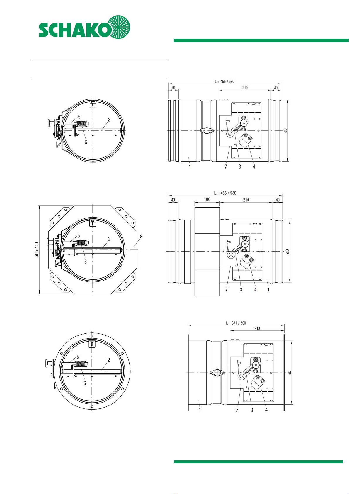
Models and dimensions
Construction subject to change
No return possible Version: 2020-09-01 | Page 10
General information
During mounting or installation, there is a risk of injuries.
To avoid any possible injuries, personal protective equip-
ment (PPE) must be worn.
Fire dampers must be installed such that external forces
do not impair their permanent functioning.
Ventilation ducts must not exert significant forces on
walls, supports or ceilings and thus also on fire dampers
as a result of thermal expansion (in case of fire).
Appropriate compensation measures, such as the ar-
rangement of flexible spigots (SCHAKO type FS-RS/-RF) or
a suitable duct routing (duct angles and distortions), must
be taken as required. National regulations must be ob-
served and adhered to.
Prior to installing the fire damper, the possibility to con-
nect the ventilation ducts must be checked. Extension
pieces (on site or as accessories SCHAKO type VT-RF) may
be necessary, for example, for large wall and ceiling thick-
nesses. When connecting duct components, a fastening
type must be selected that causes no damage to the fire
damper or its accessories.
During mounting, it may be required to provide reinforce-
ments for the housing or the like.
The requirement of statically load-bearing lintels may
have to be taken into consideration.
If a fire damper is not filled with mortar on all four sides,
installation and mounting aids on site must be removed.
Improper transport/handling may result in damage/func-
tional impairment. In addition, the film of the transport
packaging must be removed and the delivery checked for
completeness.
During storage, fire dampers must be protected from
dust, dirt, moisture and the effects of temperature (e.g.
direct sunlight, heat-emitting light source, etc.). They
must not be exposed to direct effects of the weather and
must not be stored below -20 °C or above 50 °C.
The fire damper must be protected from dirt and damage.
After installation is complete, any dirt must be removed
immediately.
Enough space must be provided for installation, mortar
lining, etc.
Carry out a functional check of the fire damper before and
after mounting and ensure ready access.
Electrical installation or work on electrical components
may only be carried out by skilled electricians. The supply
voltage must be switched off when performing this work
and secured against being switched on again.
We would like to point out that only suitable cleaning ma-
terials may be used for cleaning fire dampers in stainless
steel design!
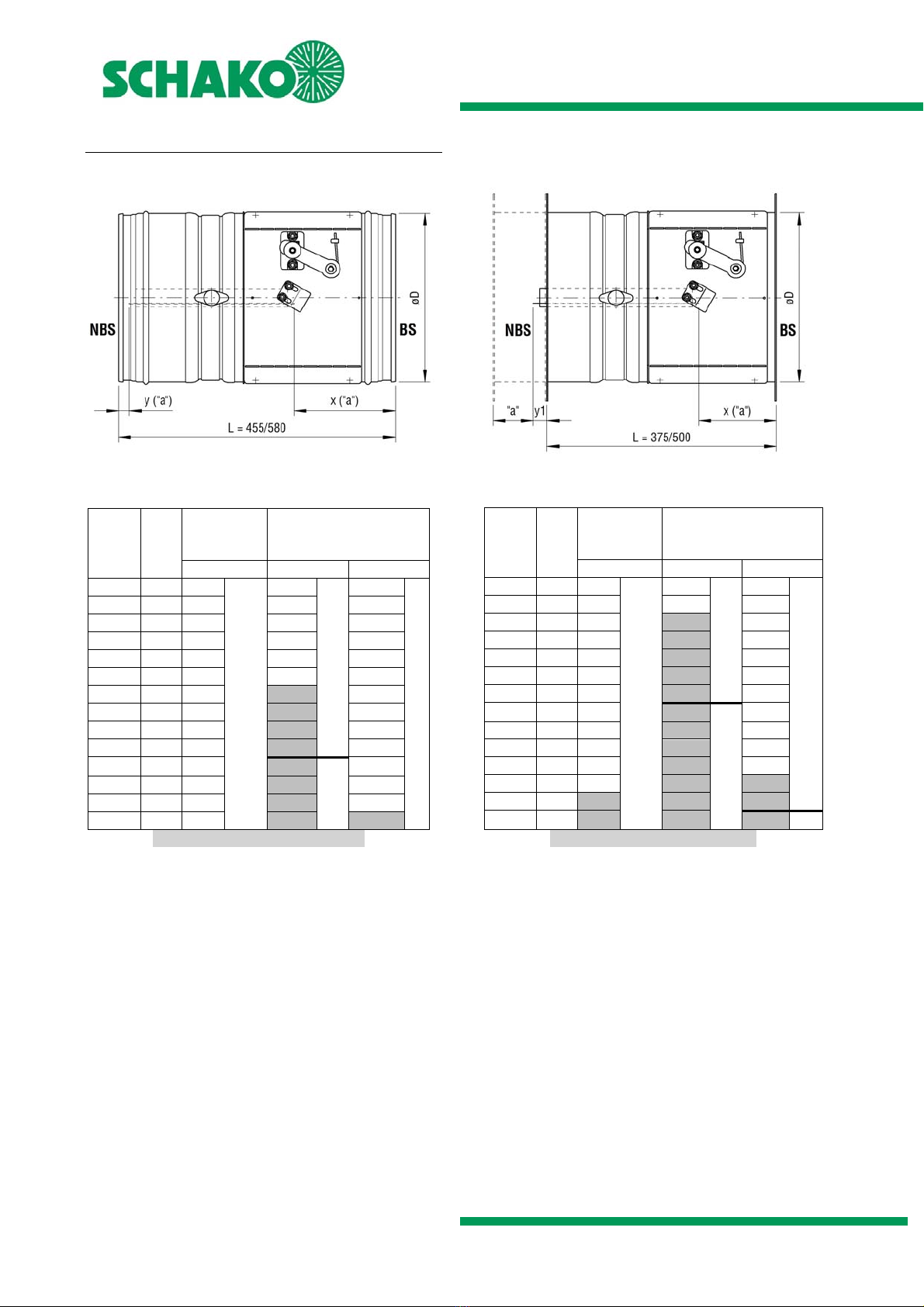
Minimum distances or projecting ends
The dimensions given must be considered an installation rec-
ommendation for the BSK-RPR and may differ, depending on
the local situation. To guarantee fire protection, the fire
damper must be installed in accordance with the technical
documentation, installation, mounting and operating instruc-
tions.
There are no inspection openings on the BSK-RPR, which is why
inspection openings in the connected ventilation ducts must
be provided in the immediate proximity. Inspection openings
must be freely accessible, which must be ensured in particular
when at least 2 fire dampers are installed next to each other
or below each other in the immediate proximity of adjacent
components.
Figure 11: Minimum distances to walls, ceilings and BSK-RPR
to one another
1.) Minimum distances recommended by SCHAKO for suffi-
cient accessibility
2.) The distance between the fire damper and the adjacent
component (wall/ceiling) must be determined according
to the particular installation situation or adjusted to the
dimensions of the projecting ends.
3.) When installing the BSK-RPR with mounting frame AR
(nominal sizes 100 - 250) on solid walls, installation is al-
lowed at a reduced distance (mounting frame AR to
mounting frame AR).
When installing the BSK-RPR (nominal sizes 100 - 500) in
solid ceilings, installation is allowed at a reduced distance
(55 mm).
In other installation situations, the distance may become
larger as a result of construction. Sufficient distance
between the mounted components must be guaranteed.
The dimension x is:
- approx. 80 mm for manual release, magnetic
clamps MH1/MH2, pulse magnets MI1/MI2
- spring return actuators B10/B11 or B42 and
S00/S01 max. approx. 90 mm
- max. approx. 170 mm for explosion-protected
spring return actuator Ex-Max-5.10-BF (X10 - X15)
The dimension y is:
- max. approx. 50mm for manual release, magnetic
clamps MH1/MH2, pulse magnets MI1/MI2 / max.
approx. 100mm for manual release with limit
switch
- spring return actuators B10/B11 or B42 and
S00/S01 max. approx. 50 mm
- max. approx. 50 mm for explosion-protected spring
return actuator Ex-Max-5.10-BF (X10 - X15)