manuals.online logo
Brands
  1. Home
  2. •
  3. Brands
  4. •
  5. Rf-t
  6. •
  7. Fire And Smoke Damper
  8. •
  9. Rf-t ONE-X CU2/B User manual

Rf-t ONE-X CU2/B User manual

Other Rf-t Fire And Smoke Damper manuals

Rf-t KAMOUFLAGE MP Series User manual

Rf-t

Rf-t KAMOUFLAGE MP Series User manual

Rf-t CU2-15 User manual

Rf-t

Rf-t CU2-15 User manual

Rf-t CR120 User manual

Rf-t

Rf-t CR120 User manual

Rf-t CA2 User manual

Rf-t

Rf-t CA2 User manual

Rf-t SC-S User manual

Rf-t

Rf-t SC-S User manual

Rf-t ONE-X CU4 User manual

Rf-t

Rf-t ONE-X CU4 User manual

Rf-t CU2 User manual

Rf-t

Rf-t CU2 User manual

Rf-t CR120 User manual

Rf-t

Rf-t CR120 User manual

Rf-t CR2 User manual

Rf-t

Rf-t CR2 User manual

Rf-t AVANTAGE DP User manual

Rf-t

Rf-t AVANTAGE DP User manual

Rf-t CU2 User manual

Rf-t

Rf-t CU2 User manual

Rf-t CRS60 User manual

Rf-t

Rf-t CRS60 User manual

Rf-t CR2 User manual

Rf-t

Rf-t CR2 User manual

Popular Fire And Smoke Damper manuals by other brands

mercor mcr ZIPP Operation and maintenance manual

mercor

mercor mcr ZIPP Operation and maintenance manual

HVC NCA 700 Series Operation and maintenance manual

HVC

HVC NCA 700 Series Operation and maintenance manual

Wildeboer FR90 user manual

Wildeboer

Wildeboer FR90 user manual

FläktGroup ETCE Instructions for installation, operation and maintenance

FläktGroup

FläktGroup ETCE Instructions for installation, operation and maintenance

Tamco 1000 SM Series manual

Tamco

Tamco 1000 SM Series manual

Greenheck Vektor-MD Installation, operation and maintenance manual

Greenheck

Greenheck Vektor-MD Installation, operation and maintenance manual

BLAUBERG Ventilatoren BSK user manual

BLAUBERG Ventilatoren

BLAUBERG Ventilatoren BSK user manual

mercor mcr FID PRO Series Operation and maintenance manual

mercor

mercor mcr FID PRO Series Operation and maintenance manual

Greenheck HPR Series Installation, operation and maintenance manual

Greenheck

Greenheck HPR Series Installation, operation and maintenance manual

Greenheck HPR Series Installation, operation and maintenance manual

Greenheck

Greenheck HPR Series Installation, operation and maintenance manual

SMAY WKP-P installation manual

SMAY

SMAY WKP-P installation manual

Komfovent UVS30 Installation instruction

Komfovent

Komfovent UVS30 Installation instruction

Mandik FDMD manual

Mandik

Mandik FDMD manual

Mandik SEDS-L Technical specifications

Mandik

Mandik SEDS-L Technical specifications

mercor mcr FID WING Technical documentation operation manual

mercor

mercor mcr FID WING Technical documentation operation manual

Lindab RECTANGULAR Series Technical manual

Lindab

Lindab RECTANGULAR Series Technical manual

Vents KP Series user manual

Vents

Vents KP Series user manual

Mandik MSD manual

Mandik

Mandik MSD manual

manuals.online logo
manuals.online logoBrands
  • About & Mission
  • Contact us
  • Privacy Policy
  • Terms and Conditions

Copyright 2025 Manuals.Online. All Rights Reserved.

www.rft.be
en
Rf-Technologies nv Lange Ambachtstraat 40 9860 Oosterzele Belgium Tel +32 9 362 31 71 Fax +32 9 362 33 07 [email protected]
0749
C31-EN-H 03/2021
CU2/B
Battery assembly of max. 4 individual dampers
2Table of content
Table of content
Declaration of performance 3
Product presentation CU2/B 4
Range and dimensions CU2/B 5
Variant CU2/B-L500 5
Range and dimensions CU2/B-L500 5
Evolution - kits 6
Options - at the time of order 9
Flange types - at the time of order 9
Storage and handling 10
Installation 10
Installation at a minimal distance from another damper or from an adjacent supporting construction 10
Installation in a rigid wall 11
Operation and mechanisms 13
Electrical connection 18
Weights 20
Sample order 24
Approvals and certificates 24
Explanation of the abbreviations and pictograms
Wn = nominal width
Hn = nominal height
Dn = nominal diameter
E = integrity
I = thermal insulation
S = smoke leakage
Pa = pascal
ve = vertical wall penetration
ho = horizontal floor penetration
o -> i = meets the criteria from the outside
(o) to the inside (i)
i <-> o = fire side not important
V AC = Volt alternating current
V DC = Volt direct current
E.TELE = power supply magnet
E.ALIM = power supply motor
V = volt
W = watt
Auto = automatic
Tele = remote controlled
Pnom = nominal capacity
Pmax = maximum capacity
GKB (type A) / GKF (type F): “GKB”
stands for standard plasterboards (type
A according to EN 520) while “GKF”
plasterboards offer a higher fire resistance
for a similar plate thickness (type F
according to EN 520)
Cal-Sil = calcium silicate
OP = option (delivered with the product)
KIT = kit (delivered separately for repair or
upgrade)
PG = connection flange to the duct
Sn = free air passage
ζ [-] = pressure loss coefficient
Q = airflow
∆P = static pressure drop
v = air speed in the duct
Lwa = A-weighted sound power level
Lw oct = sound power level per octave
midband
dB(A) = A-weighted decibel value
∆L = correction factor
battery assembly tested in rigid wall suitable for built-in installation
intermediate dimensions on request
3
Declaration of performance
F-05/2018CE_DoP_Rf-t_C31_EN
DECLARATION OF PERFORMANCE
Declarationofperformance
CE_DoP_Rf-t_C31_EN
F-05/2018
1. Unique identication code of the product-type: CU2/B
2. Intended use/es: Rectangular re damper to be used in conjunction with partitions to maintain re compartments in heating, ventilating and air conditioning installations.
3. Manufacturer: Rf-Technologies NV, Lange Ambachtstraat 40, B-9860 Oosterzele
4. System/s of AVCP: System 1
5. Harmonised standard / European Assessment Document; notied body / European Technical Assessment, Technical Assess-
ment Body, notied body; certicate of constancy of performance:
EN 15650:2010, BCCA with identication number 0749; BCCA-0749-CPR-BC1-606-0464-15650.03-0464; BCCA-0749-CPR-BC1-606-0464-15650.13-0464;
6. Declared performance according to EN 15650:2010 (Fire resistance according to EN 1366-2 and classications according to EN 13501-3)
Essential characteristics Performance
Range Wall type Wall Sealing Installation Classication
CU2/B ≤ 4 x CU2 (200x200 mm ≤ CU2 ≤ 1200x800 mm) Rigid wall Reinforced concrete ≥ 110 mm Mortar 1 EI 120 (vei no) S - (500 Pa)
CU2/B ≤ 4 x CU2 (200x200 mm ≤ CU2 ≤ 1500x800 mm) Rigid wall Reinforced concrete ≥ 110 mm Mortar 1 EI 120 (vei no) S - (300 Pa)
EI 60 (ve i no) S - (500 Pa)
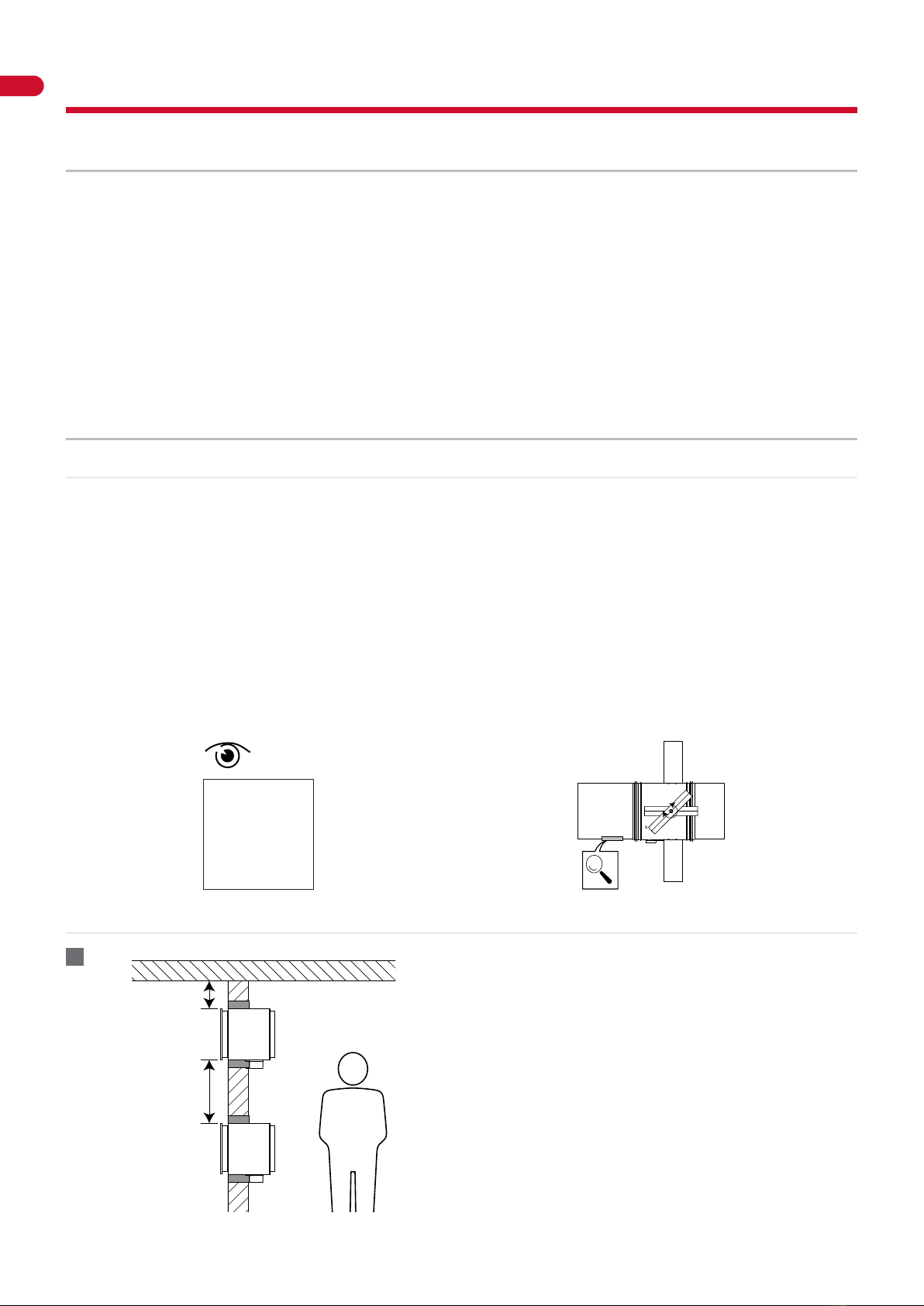
1 Type of installation: built-in 0/180° (B22, B21, B12)
B22 B21 B12
Essential characteristics Performance
Nominal activation conditions/sensitivity: Pass
Response delay (response time): closure time Pass
Operational reliability: cycling CFTH - 50 cycles; MANO - 300 cycles; B(L)F(T) - 10000 cycles; BFL(T) - 10000 cycles; BFN(T) - 10000 cycles; ONE - 10000 cycles; UNIQ - 10000 cycles
Durability of response delay: Pass
Durability of operational reliability: Pass
Protection against corrosion according to EN 60068-2-52: Pass
Damper casing leakage according to EN 1751: ≥ class B
Harmonised standard
EN 15650:2010
The performance of the product identied above is in conformity with the set of declared performance/s. This declaration of
performance is issued, in accordance with Regulation (EU) No 305/2011, under the sole responsibility of the manufacturer identi-
ed above.
Signed for and on behalf of the manufacturer by:
Frank Verlinden, Product Manager
Oosterzele, 05/2018
4Product presentation CU2/B
Product presentation CU2/B
The CU2/B damper is a battery assembly of several CU2 dampers with maximum 4 individual dampers (B12, B21 or B22) and with a
fire resistance up to 120 minutes. The CU2/B battery assembly is the ideal solution for installations with large dimensions.
Fire dampers are installed where air ducts penetrate fire-resistant compartment walls. Their role is to restore the fire resistance grade
of the penetrated wall and to prevent smoke propagation. Fire dampers are distinguished by their degree of fire resistance, by their
aeraulic properties as well as by their installation ease. Rf-Technologies’ fire dampers are all CE marked. They can be equipped with
various types of mechanisms depending on the specific needs linked to the project or to the local regulations.
5large dimensions
5battery assembly tested in rigid wall
∎tested according to EN 1366-2 up to 500 Pa
∎suitable for installation in rigid wall
∎maintenance-free
∎for indoor use
∎suitable for built-in installation
∎intermediate dimensions on request
1. individual damper with PG25 flange and connection pieces in Promatect
2. EPDM foam
3. connection piece
4. central plate (B22)
1
2
3
4
Range and dimensions CU2/B
Exceeding blade: X = on the mechanism side, Y = on the wall side
YX
45
400
240
(Wn-6)x(Hn-6)
(Wn+24)x(Hn+24)
Hn [mm] 300 350 400 450 500 550 600 650 700 750 800
x - - - - - 1 26 51 76 101 126
y 2 27 52 77 102 127 152 177 202 227 252
≥ ≤
(W x H) mm 200x200 1500x800
Possibilities: B12, B21, B22 (number of dampers in width / number of dampers in height)
B1 B2
H2H1
Hn+50
Hn-6
Bn+50
Bn-6
Width:
B multiple of 100: B1 = (Bn-100)/2, B2 = Bn/2;
B ending with 50: B1 = B2 = (Bn-50)/2.
Height:
H multiple of 100: H1 = (Hn-100)/2, H2 = Hn/2;
H ending with 50: H1 = H2 = (Hn-50)/2.
5
Variant CU2/B-L500
Variant CU2/B-L500
The CU2/B-L500 damper is a battery assembly of several CU2-L500 dampers with maximum 4 individual dampers (B12, B21 or B22).
This version ensures that the damper blade doesn’t exceed the casing at the wall side (up to a height of 500 mm).
Range and dimensions CU2/B-L500
Wn/Hn in steps of 50 mm; intermediate dimensions are subject to extra cost (heights between ≥ 275 and ≤ 299 mm are not possible).
Exceeding blade: X = on the mechanism side, Y = on the wall side
YX
45
240
500
(Wn-6)x(Hn-6)
(Wn+24)x(Hn+24)
Hn [mm] 500 550 600 650 700 750 800
x - 1 26 51 76 101 126
y 2 7 52 77 102 127 152
≥ ≤
(W x H) mm 200x200 1500x800
Possibilities: B12, B21, B22 (number of dampers in width / number of dampers in height)
B1 B2
H2H1
Hn+50
Hn-6
Bn+50
Bn-6
Width:
B multiple of 100: B1 = (Bn-100)/2, B2 = Bn/2;
B ending with 50: B1 = B2 = (Bn-50)/2.
Height:
H multiple of 100: H1 = (Hn-100)/2, H2 = Hn/2;
H ending with 50: H1 = H2 = (Hn-50)/2.
6Evolution - kits
Evolution - kits
KITS ONE T 24 FDCB Spring return actuator ONE 24V (with fusible link T) + bipolar beginning- and end-of-
range switch
KITS ONE T 24 FDCU Spring return actuator ONE 24V (with fusible link T) + unipolar beginning- and end-of-
range switch
KITS ONE T 230 FDCU Spring return actuator ONE 230V (with fusible link T) + unipolar beginning- and end-of-
range switch
KITS ONE T 230 FDCB Spring return actuator ONE 230V (with fusible link T) + bipolar beginning- and end-of-
range switch
KIT ONE-X 24 Spring return actuator ONE-X 24V (with fusible link T)
KIT ONE-X 230 Spring return actuator ONE-X 230V (with fusible link T)
KITS CFTH Automatic unlocking mechanism CFTH with FCU and without FTH 72
KITS BFL24 Spring return actuator BFL 24V
KITS BFL230 Spring return actuator BFL 230V
7
Evolution - kits
KITS BFL24-ST Spring return actuator BFL 24V with plug (ST)
KITS BFLT24 Spring return actuator BFL 24V with thermo-electric fuse (T)
KITS BFLT230 Spring return actuator BFL 230V with thermo-electric fuse (T)
KITS BFLT24-ST Spring return actuator BFL 24V with thermo-electric fuse (T) and plug (ST)
KITS BFN24 Spring return actuator BFN 24V
KITS BFN24 Spring return actuator BFN 24V (BFN kits must be used instead of BFL kits for fire dampers
produced before 1/7/2015)
KITS BFN230 Spring return actuator BFN 230V
KITS BFN24-ST Spring return actuator BFN 24V with plug (ST)
KITS BFNT24 Spring return actuator BFN 24V with thermo-electric fuse (T)
8Evolution - kits
KITS BFNT230 Spring return actuator BFN 230V with thermo-electric fuse (T)
KITS BFNT24-ST Spring return actuator BFN 24V with thermo-electric fuse (T) and plug (ST)
KITS BFNT24 CRE Spring return actuator BFN 24V with thermo-electric fuse (T)
KITS BFNT230 CRE Spring return actuator BFN 230V with thermo-electric fuse (T)
KITS BFNT24-ST CRE Spring return actuator BFN 24V with thermo-electric fuse (T) and plug (ST)
KITS BF24 Spring return actuator BF 24V (BF kits must be used instead of BFN kits for fire dampers
produced before 1/7/2015)
KITS FDC CFTH 1 limit switch (FCU/DCU/FCB/DCB)
KITS SN2 BFL/BFN Auxiliary limit switch ‘open/closed’
KITS FTH72 Fusible link FTH 72°C (for CFTH)
9
Options - at the time of order
KITS ZBAT 72 Black spare part for thermo-electric fuse for BFLT/BFNT
FUS72 ONE Fusible link 72°C
MECT Testbox for mechanisms 24/48 V (magnet, motor, beginning and end of range switches)
KITS EQ Kit equipotential connection (per set of 5 pieces)
Options - at the time of order
EQ Equipotential connection
ONE-X CN Connectors for the bus cables and the power cable.
Flange types - at the time of order
28.5
2525
400
25 25
HnxWn
(Hn-6)x(Wn-6)
PG25 Connection to ducts with 20 and 30 mm flanges (with bolts).
Elliptical holes Ø 8,5 x 16 mm.
10 Storage and handling
Storage and handling
As this product is a safety element, it should be stored and handled with care.
Avoid:
• any kind of impact or damage
• contact with water
• deformation of the casing
It is recommended:
• to unload in a dry area
• not to flip or roll the product to move it
• not to use the damper as a scaffold, working table, etc.
• not to store smaller dampers inside larger ones
Installation
General points
∎The installation must comply with the installation manual and the classification report.
∎Axis orientation: see the declaration of performance.
∎Avoid obstruction of adjoining ducts.
∎Product installation: always with closed damper blade.
∎Verify if the blade can move freely.
∎Please observe safety distances with respect to other construction elements. The operating mechanism must also remain
accessible: allow for a clearance of 200 mm around the housing.
∎The air tightness class will be maintained if the damper is installed according to the installation manual.
∎Rf-t fire dampers are always tested in standardised constructions according to EN 1366-2. The achieved results are valid for similar
supporting constructions with a fire resistance, thickness and density equal or superior to the supporting construction used
during the test.
∎The damper must remain accessible for inspection and maintenance.
∎Schedule at least 2 visual checks each year.
2017
2018
2019
2020
2021
TEST
 | 
 | 
 | 
 | 
 | 
Installation at a minimal distance from another damper or from an adjacent supporting construction
≥ 75 mm
≥ 200 mm
1. Principle
According to the European test standard, a fire damper must
be installed at a minimum distance of 75 mm from an adjacent
wall and 200 mm from another damper, unless the solution was
tested at a shorter distance.
1