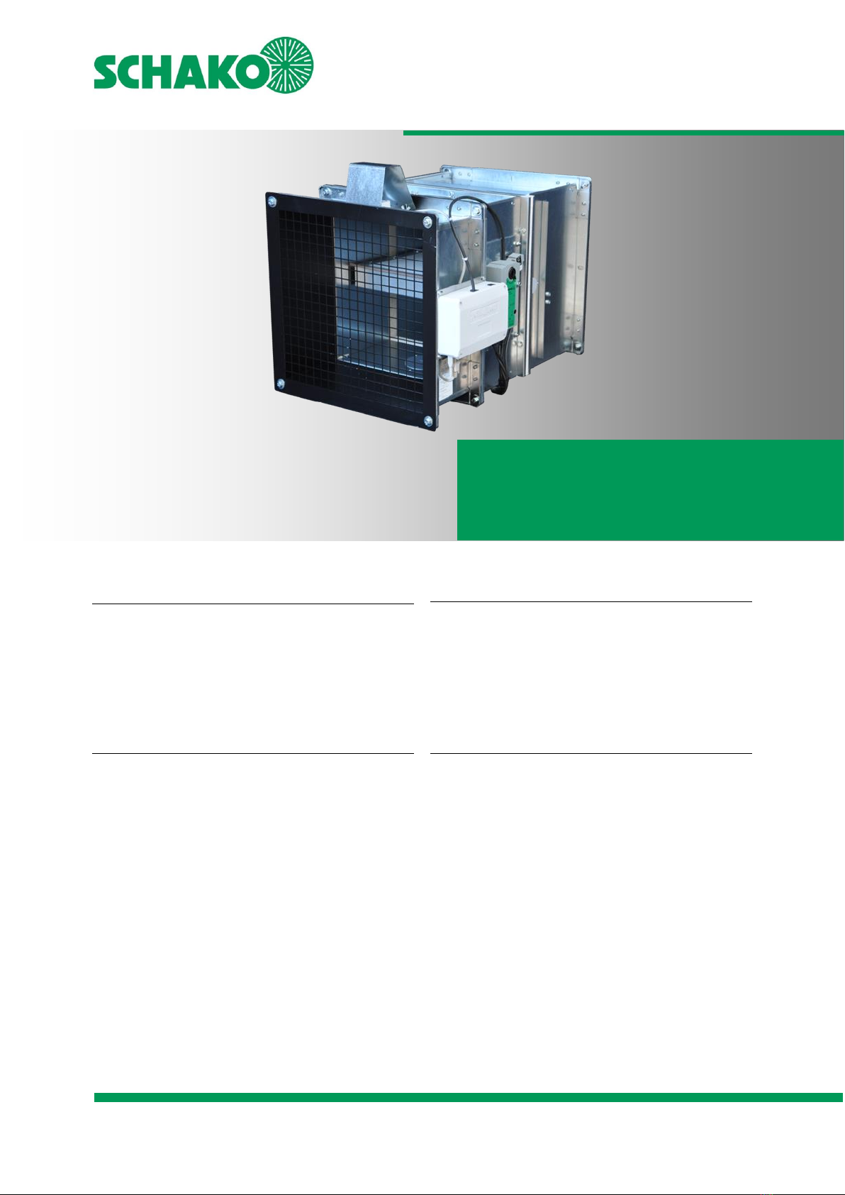
Fire-resistant damper model BKA-Ü
Technical documentation
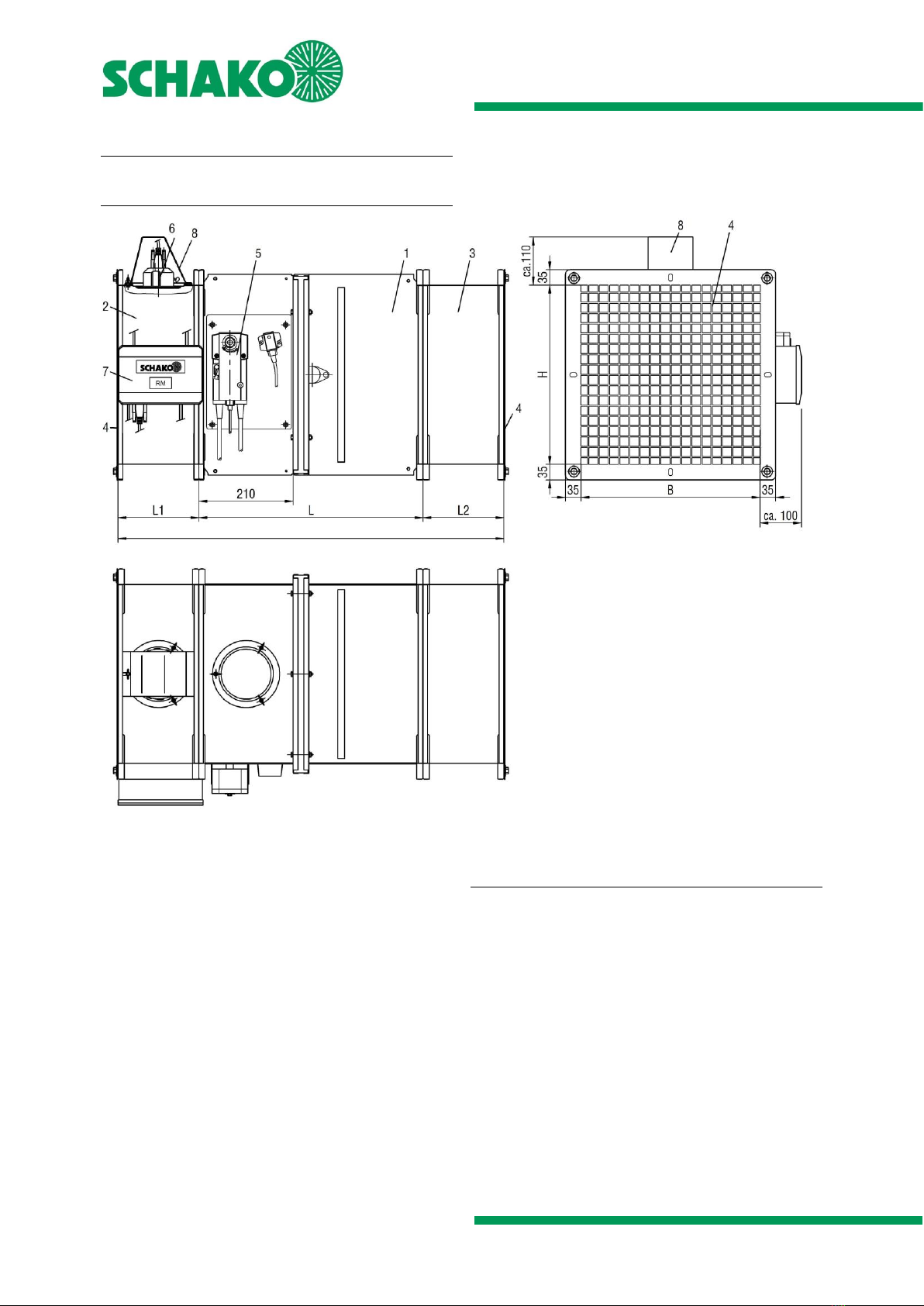
Models and dimensions
Construction subject to change
No return possible Version: 2021-07-01 | Page 7
General information
During mounting or installation, there is a risk of injuries.
To avoid any possible injuries, personal protective equip-
ment (PPE) must be worn.
Fire-resistant dampers must be installed such that exter-
nal forces do not impair their continuous functioning.
During mounting it may be required to provide reinforce-
ments for the housing or the like.
The requirement of statically load-bearing lintels may
have to be taken into consideration.
If a fire-resistant damper is not filled with mortar on all
four sides, installation and mounting aids on site must be
removed.
Improper transport/handling may result in damage/func-
tional impairment. In addition to that, the film of the
transport packaging must be removed and the delivery in-
spected for completeness.
In storage, fire-resistant dampers must be protected from
dust, dirt, moisture and the effects of temperature (e.g.
direct sunlight, heat-emitting light source etc.). They must
not be exposed to direct effects of the weather and must
not be stored below -20 C or above 50 C.
The fire-resistant dampers must be protected from soiling
and damage. After installation is complete, any dirt must
be removed immediately.
Enough space must be provided for installation, mortar
lining, etc.
Perform a functional check of the fire-resistant dampers
before and after mounting and ensure ready access.
Electrical installation or work on electrical components
may only be carried out by skilled electricians. The supply
voltage must be switched off when performing this work
and secured against being switched on again.
We point out that only suitable cleaning materials may be
used for cleaning the fire-resistant damper in stainless
steel design!
The construction company which has built the fire
damper must provide a confirmation for each building
project to verify its conformity with the general type ap-
proval (see § 16 a Section. 5, 21 Section 2 of model buil-
ding regulation).
The confirmation must be executed in writing and must
include at least the following information:
- Z-6.50-2012
- fire-resistant damper, type "BKA-Ü",
of special design and application
- Name and address of the construction company
- Designation of the building
- Date of construction /date of completion
- Place and date of issue and
signature of the person responsible
This declaration of compliance has to be handed over to
the building owner for possible forwarding to the respon-
sible building supervision authority.
Sample of a certificate of conformity see page 38
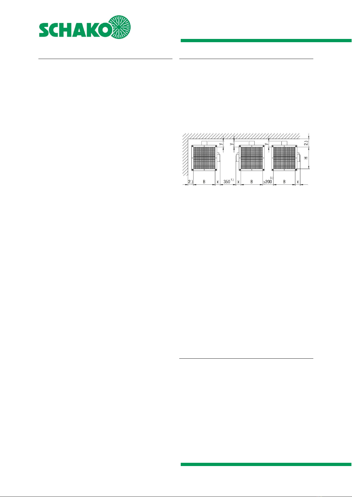
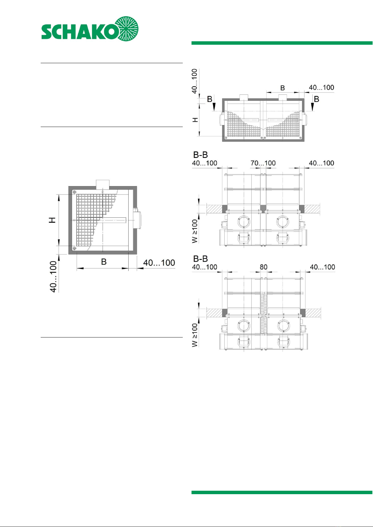
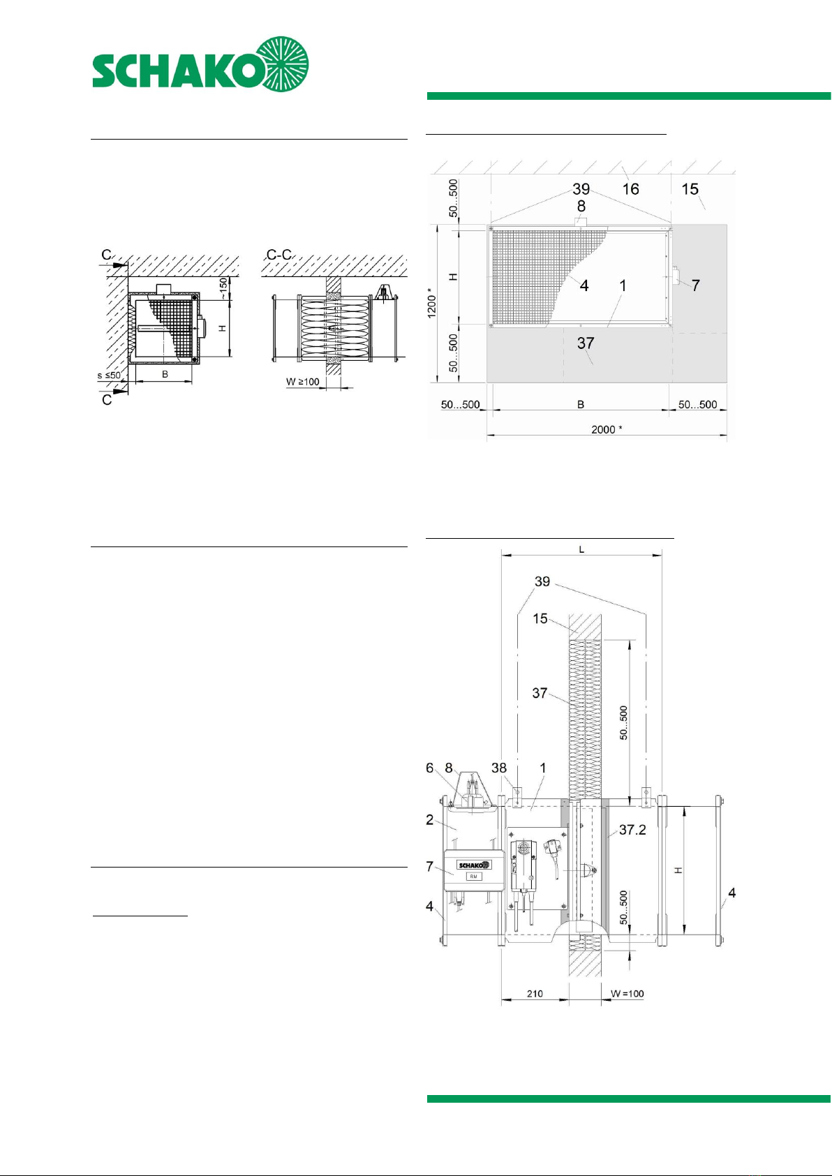
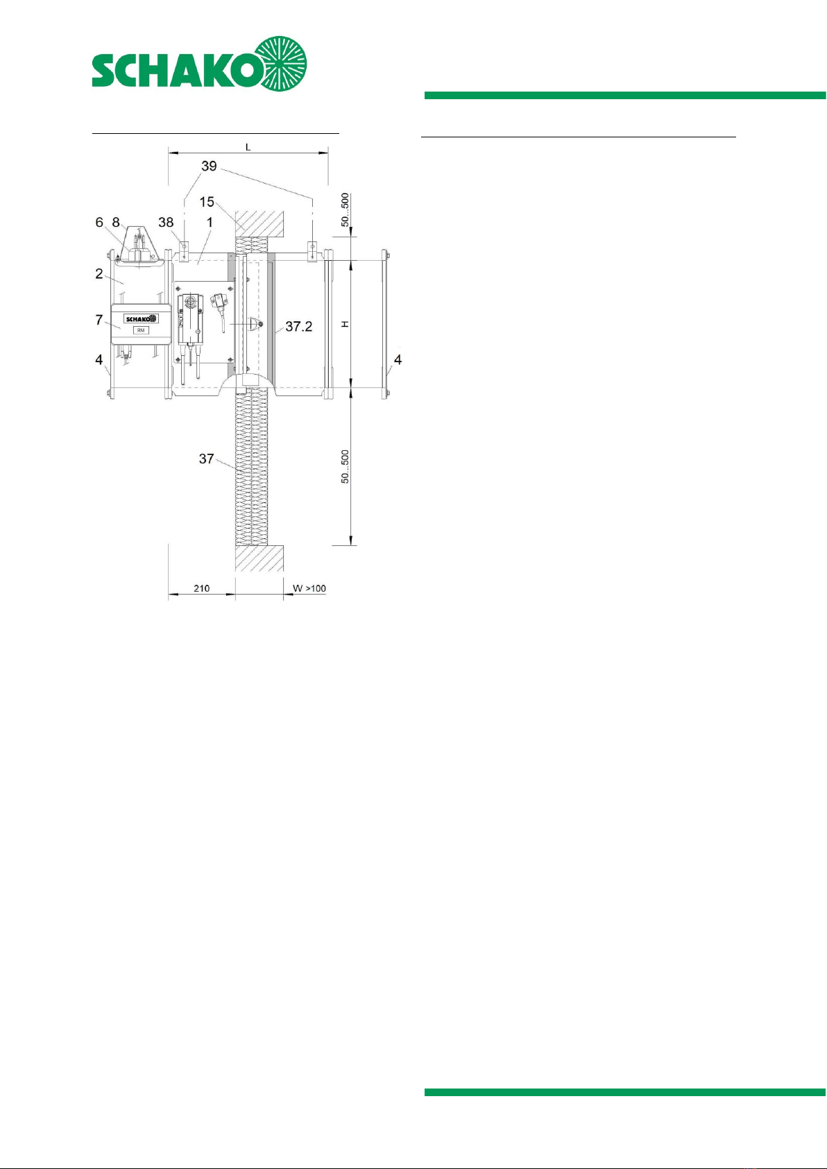
Minimum distances or projecting ends
The dimensions given must be considered an installation rec-
ommendation for the BKA-Ü and may differ, depending on the
local situation. The installation must be performed according
to the technical documentation, installation, mounting and
operating instructions in combination with the currently valid
aBG. Pay attention to the accessibility when installing 2 BKA-
Üs next to each other or in the direct vicinity of adjacent com-
ponents. For wall installation, the smoke detector must al-
ways be installed above in the assembly part type EBT with
the damper blade axle in the horizontal position.
Figure 2: Minimum distances to walls, ceilings and to one
another
1) Minimum distance recommended by SCHAKO for suffi-
cient accessibility.
2) The distance between BKA-Ü and the adjacent compo-
nent (wall/ceiling) must be determined according to the
particular installation situation or adjusted to the dimen-
sions of the projecting ends. The minimal dimension of
150 mm in the area of installed RMSII-L must be observed.
3) In solid walls and solid ceilings, installation of no more than
2 BKA-Ü can be effected at a reduced distance "flange-to-
flange". This may lead to a situation in which the inspection
openings are no longer freely accessible. In other installation
situations, the distance may become larger as a result of con-
struction. Sufficient distance between the mounted compo-
nents must be guaranteed.
The projection length x is:
- approx. 90 mm with spring return actuators
- approx. 95 mm with relay module RM
The projection length y is:
- approx. 110 mm with smoke detector RMSII-L
Wet installation (mortar lining)
If the installation of the fire-resistant damper is carried
out by mortar lining, it must be completely filled with
mortar of class M 10 to M 15 according to EN 998-2, or
fire protection mortar of suitable grades, or with concrete
or plaster mortar suitable for the wall or ceiling type.
If the fire-resistant damper is installed during the assem-
bly of the wall/ceiling, the annular gap dimensions can be
smaller than specified.
The mortar bed depth must be designed according to the
minimum wall or ceiling thickness and may not be less
than this thickness.
The mortar lining must be executed such that it is perma-
nent. The information given by the mortar manufacturer
must be observed.