Fire Damper Model BSK-RPR
Additional operating instructions according to ATEX 94/9/EC
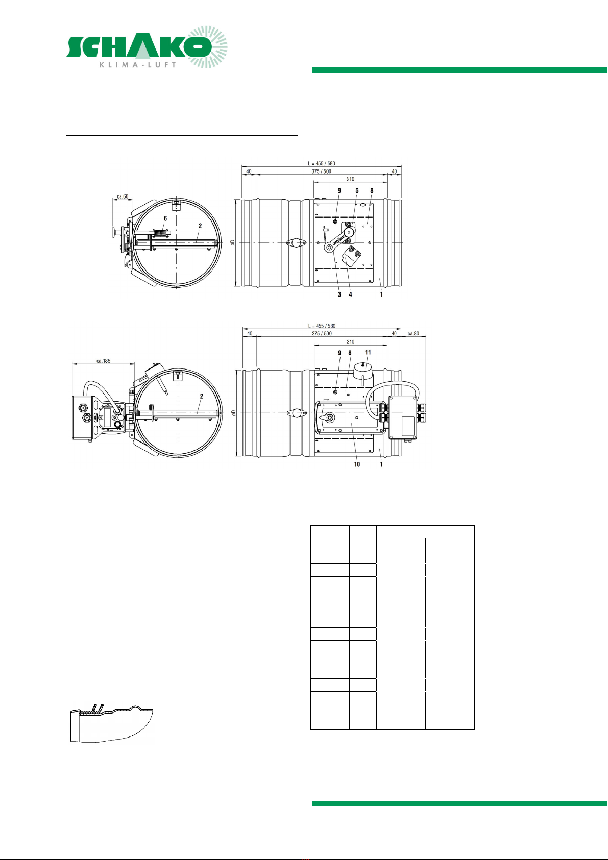
MODELS AND DIMENSIONS
Construction subject to change
No return possible Version: 2015-08-17 | Document: Z09/46 | Page 9
Information regarding assembly and commissioning
Prior to being installed in the ventilation system, the fire
damper must be checked for damage. Damaged fire damp-
ers must not be installed.
The device may only be used in accordance with its desig-
nated use in air ventilation systems for supply air and return
air.
Use only approved fastening material for mounting.
No additional parts may be
fastened to the fire damper.
The fire damper must be connected to the ventilation duct
network on both sides in electrically conducting fashion.
In order to avoid the risk of static charges, the fire damper
must be connected to the on-site equipotential bonding on
the grounding connection provided for this purpose.
Make sure that the ventilaton systems are not subjected to
any anomalous operating conditions, such as vibrations,
pressure surges or high proportions of solids in the medium.
Information regarding maintenance and inspection
Proper maintenance increases operational safety and the
service life of the device. This is why the devices should be
subjected to regular inspection.
If inspection dates are prescribed by law, they must be com-
plied with.
The operating personnel must be informed, prior to starting
maintenance and inspection work.
The personal safety measures must be looked up in the safe-
ty data sheet. Hazard caused by contact or inhaling hazard-
ous substances must be excluded by taking appropriate safe-
ty measures.
Prior to maintenance or inspection, all system components
up- and downstream of the device must be switched off and
secured against being switched on again.
The following inspection criteria must be observed:
Visual inspection of the device
Check the fastening of the device
Check the electrical connections
Check the grounding connection for tight fit and good
contact.
Functional check
For additional inspections, please refer to the technical
documentation or additional maintenance instructions.
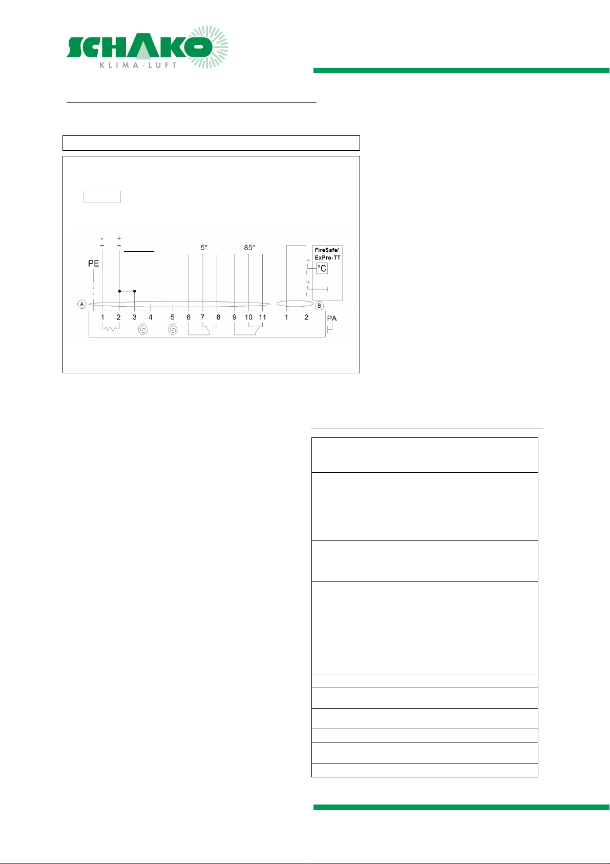
Use and electrical connection of actuators in areas
subject to explosion hazards
Only ATEX-approved electrical equipment according to ATEX
Directive 94/9/EC for Zones 1, 2, 21, 22, such as actuators,
terminal boxes and thermocouples as specified by SCHAKO
KG may be used for devices from SCHAKO KG.
The connection lines must be installed for permanent use
and in such a way that they are sufficiently protected from
mechanical and thermal damage.
Devices with explosion-protected drives and terminal boxes
have to be attached over the external potential connecting
terminal to the potential equalisation provided by the cus-
tomer with at least 4 mm² cooper solid-core.
The electrical connection lines of the actuators
must be connected in a terminal box according to ATEX Di-
rective 94/9/EC for Zones 1, 2, 21, 22 if the electrical connec-
tion is made in the area subject to explosion hazards.
The dimensioning of the conductor cross-sections must be
observed.
The actuators are maintenance-free with respect to their
function, but the relevant maintenance regulations accord-
ing to ATEX directives or factory regulations must be ob-
served.