Schako BSK-RPR-EU Service manual

SCHAKO KG Phone +49 (0) 7463-980-0
Steigstraße 25-27 Fax +49 (0) 7463-980-200
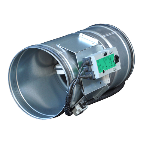
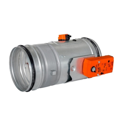
Fig.: BSK-RPR-EU with B10 drive
USABILITY CERTIFICATES
•Declaration of Performance
DoP-BSK-RPR-EU-2017-08-09
CLASSIFICATION AND STANDARDS
•Classification
according to EN 13501-3, depending on the
mounting situation EI 120 (vei↔o) S
•Product standard
EN 15650
•Test standard
EN 1366-2
PERFORMANCE DATA
•For automatic locking of fire lobbies
•For use or connection of a smoke release device
with abZ (e.g. SCHAKO smoke detection system
RMS) in connection with suitable release de-
vices (e.g. spring return actuator)
SPECIAL FEATURES
•Extensive uses and applications
•Housing leakage class C according to EN 1751
•For optimum integration into the building con-
trol system via the SCHAKO EasyBus signalling
and switching bus system or the SCHAKO BKSYS
fire damper mini-controller
Technical documentation
Installation, mounting and operating instructions
BSK-RPR-EU
Fire damper

Fire damper BSK-RPR-EU
Technical documentation
Table of Contents
Construction subject to change
No return possible Version: 2021-07-01 | Page 2
TABLE OF CONTENTS
Table of Contents........................................................ 2
Description.................................................................. 3
Models and dimensions.............................................. 4
Installation in solid walls............................................. 8
Wet installation of a fire damper, complete mortar
lining ........................................................................... 8
Wet installation at a reduced distance....................... 8
Installation information .............................................. 9
Connection of ventilation ducts.................................. 9
Technical data........................................................... 10
Accessories ............................................................... 12
Limit switch............................................................... 12
Spring return actuators............................................. 13
Add-on parts ............................................................. 17
CE marking................................................................ 18
Order code................................................................ 19
Specification texts..................................................... 21
Commissioning and maintenance............................. 23
Foreign branch offices .............................................. 27
List of figures/tables/diagrams................................. 28

Fire damper BSK-RPR-EU
Technical documentation
Description
Construction subject to change
No return possible Version: 2021-07-01 | Page 3
DESCRIPTION
Fire dampers, installed in ventilation ducts (air conditioning
systems), serve for the automatic locking of fire lobbies.
The fire damper BSK-RPR-EU corresponds to EN 15650, EN
13501-3 and EN 1366-2.
The BSK-RPR-EU has been tested according to EN 1366-2 in com-
pliance with Declaration of Performance no. DoP-BSK-RPR-EU-
2017-08-09. Its classification according to EN 13501-3 is EI 120
(vei o) S.
The national standards and guidelines must be observed in
connection with this technical documentation, installation,
mounting and operating instructions.
For functional test, service, retrofitting, etc., inspection open-
ings must be provided on site in suspended ceilings, shaft
walls, connected ventilation ducts, etc., if necessary. They
must be built in in sufficient numbers and sizes and must not
impair the functioning of the fire dampers.
The fire dampers must be connected to the ventilation system
by means of ventilation ducts either on one or on both sides.
When connected on one side, finishing protective gratings
made of non-flammable building materials (EN13501-1) must
be provided on the opposite side.
The fire dampers can be connected to non-flammable and
flammable ventilation ducts as well as to flexible spigots.
Housing made of galvanised sheet steel (standard), option-
ally (at an extra charge):
Housing made of stainless steel material no. 1.4301
or material no. 1.4571
Housing with DD coating (two-component top coat
based on polyurethane varnish) inside / outside
Model with plug-in connection (-S) or flanged connection
(-F) according to EN 12220 and DIN 24154-1, respectively.
Damper leaf made of silicate board,
optionally (at an extra charge):
DD coating (RAL 7035 / light-grey)
Cold and hot leakage requirements according to EN 1366-
2 are complied with using circumferential rubber and intu-
mescent seals.
Horizontal position of the damper blade axle
The installation position is independent of the air flow di-
rection.
Thermal trigger via fusible link 72°C;
optionally (at an extra charge)
equipped with electrical release devices
Use: max. operating pressure of 1000 Pa at vface ≤ 10 m/s
Housing leakage class C according to EN 1751
Use or connection of a smoke trigger device with general
building supervisory approval (e.g. SCHAKO smoke detection
system RMS, see technical documentation smoke detection
system RMS) in connection with suitable electric release de-
vices of the fire damper is possible; only release devices
working by the "currentless closed" principle may be con-
nected to the RMS system; the propagation of fire and
smoke is effectively prevented. Optimal integration into the
building control system by means of the SCHAKO EasyBus
signalling and switching bus system (see technical documen-
tation EasyBus) or the SCHAKO fire damper mini-controller
BKSYS (see technical documentation BKSYS).
ATTENTION
Building systems have to be arranged, installed, changed and
maintained in such a way that they prevent fire and propaga-
tion of fire and smoke (fire propagation) and allow evacuation
of people and animals as well as efficient fire extinguishing
work.
Smoke propagation through the air-conditioning and ventila-
tion system can be prevented for example by means of fire
dampers and spring return actuators in combination with ap-
proved smoke detector devices (e.g. SCHAKO smoke detection
system RMS).
GENERAL
Data and requirements according to German standards (DIN)
must be checked on site for compatibility with current stand-
ards and directives in the respective states/countries and
adapted, if necessary. Whether the installation of flexible con-
nection pieces is required, must be determined on site.
Fire damper BSK-RPR-EU
Technical documentation
Models and dimensions
Construction subject to change
No return possible Version: 2021-07-01 | Page 4
MODELS AND DIMENSIONS
BSK-RPR-EU
BSK-RPR-EU-S (plug-in connection)
Figure 1: Dimensions BSK-RPR-EU-S
BSK-RPR-EU-F (flanged connection)
Figure 2: Dimensions BSK-RPR-EU-F
1
Fire damper BSK-RPR-EU
2
Damper blade
3
Hand lever
4
Locking profile
5
Release device
6
Fusible link
7
Actuator unit

Fire damper BSK-RPR-EU
Technical documentation
Models and dimensions
Construction subject to change
No return possible Version: 2021-07-01 | Page 5
Available sizes
No-
minal
size
øD
mm
L mm
BSK-RPR-EU-S
BSK-RPR-EU-F
100
98
125
123
140
138
160
158
180
178
455
375
200
198
224
222
or
or
250
248
280
278
580
500
315
313
(standard)
(standard)
355
353
400
398
450
448
500
498
Table 1: Available sizes
Rubber lip seal for BSK-RPR-EU-S
Model BSK-RPR-EU-S is delivered by default with a rubber lip
seal.
Figure 3: Rubber lip seal
Flange bores BSK-RPR-EU-F
Figure 4: Flange bores
Table to DIN EN 12220 or DIN 24154-1
Nomi-
nal
size
øD
mm
øC
mm
Bolt circle
øB
Number of
bores
(± 0.5mm)
Ø9.5 (± 0.5mm)
100
98
150
132
4
125
123
175
157
4
140
138
190
172
6
160
158
210
192
6
180
178
230
212
6
200
198
250
233
6
224
222
274
257
6
250
248
300
283
6
280
278
340
317
8
315
313
375
352
8
355
353
415
392
8
400
398
460
438
8
450
448
510
488
8
500
498
560
538
8
Table 2: Flange bores
SCHAKO ASG-RF / VT-RF / FS-RF: Flange bores suitable for
BSK-RPR-EU-F

Fire damper BSK-RPR-EU
Technical documentation
Models and dimensions
Construction subject to change
No return possible Version: 2021-07-01 | Page 6
Damper leaf projecting ends
BSK-RPR-EU-S
Figure 5: Damper blade projecting ends BSK-RPR-EU-S
No-
minal
size
øD
Operating
side
(BS)
Non-operating side
(NBS)
L=455 / 580
L=455
L=580
100
98
256
x
107
Y
232
y
125
123
244
95
220
140
138
236
87
212
160
158
226
77
202
180
178
216
67
192
200
198
206
57
182
224
222
194
45 *
170
250
248
181
32 *
157
280
278
166
17 *
142
315
313
149
0 *
125
355
353
129
20 *
Y1
105
400
398
106
43 *
82
450
448
81
68 *
57
500
498
56
93 *
32 *
* Extension piece (on site) necessary
Table 3: Damper blade projecting ends BSK-RPR-EU-S
"a"= 50
mm:
Minimum distance between the front edge
of the open damper blade and the finishing
protective grating (ASG-RF/-RS)
Use
Table 4: Usability
BSK-RPR-EU-F
Figure 6: Damper blade projecting ends BSK-RPR-EU-F
No-
minal
size
øD
Operating
side
(BS)
Non-operating side
(NBS)
L=375 / 500
L=375
L=500
100
98
216
x
67
Y
192
y
125
123
204
55
180
140
138
196
47 *
172
160
158
186
37 *
162
180
178
176
27 *
152
200
198
166
17 *
142
224
222
154
5 *
130
250
248
141
8 *
Y1
117
280
278
126
23 *
102
315
313
109
40 *
85
355
353
89
60 *
65
400
398
66
83 *
42 *
450
448
41 *
108 *
17 *
500
498
16 *
133 *
8 *
Y1
* Extension piece (VT-RF) necessary
Table 5: Damper blade projecting ends BSK-RPR-EU-F
The fire damper type BSK-RPR-EU can be installed as shown in the following table
Use
Installa-
tion
Material/Model
Minimum
thickness
mm
Minimum
distance
mm
Fire resistance
class
Notes
Page °
WALL
solid
Apparent
density
≥ 450kg/m³
in
Wet installation in, for example,
concrete; masonry according to EN
1996 or DIN 1053; solid plaster
wall boards according to EN 12859
150
next to each other: 50
1)
EI 120 (veio) S
8
Wall: 75
Ceiling: 75
1) The allowed minimum distance of the fire dampers to one another is at least 50 mm. However, due to the construction, the distance
has to be adapted for BSK-RPR-EU-F, if necessary.
NBS BS
NBS BS

Fire damper BSK-RPR-EU
Technical documentation
Models and dimensions
Construction subject to change
No return possible Version: 2021-07-01 | Page 7
General information
During mounting or installation, there is a risk of injuries. To
avoid any possible injuries, personal protective equipment
(PPE) must be worn.
Fire dampers must be installed such that external forces do not
impair their permanent functioning.
Ventilation ducts must not exert significant forces on walls,
supports or ceilings and thus also on fire dampers as a result
of thermal expansion (in case of fire).
Appropriate compensation measures, such as the arrange-
ment of flexible spigots or a suitable duct routing (duct angles
and distortions), must be taken as required. National regula-
tions must be observed and adhered to.
Prior to installing the fire damper, the possibility to connect
the ventilation ducts must be checked. Extension pieces (on
site or as accessories SCHAKO type VT-RF) might be neces-
sary, e.g. for large wall and ceiling thicknesses. When con-
necting duct components, a fastening type must be selected
that causes no damage to the fire damper or its accessories.
During mounting it may be required to provide reinforce-
ments for the housing or the like.
The requirement of statically load-bearing lintels may have to
be taken into consideration.
Improper transport/handling may result in damage/functional
impairment. In addition to that, the film of the transport
packaging must be removed and the delivery inspected for
completeness.
During storage, fire dampers must be protected from dust,
dirt, moisture and the effects of temperature (e.g. direct sun-
light, heat-emitting light source, etc.). They must not be ex-
posed to direct effects of the weather and must not be stored
below -20 °C or above 50 °C.
The fire damper must be protected from dirt and damage. Af-
ter installation is complete, any dirt must be removed imme-
diately.
Enough space must be provided for installation, mortar lining,
etc.
Carry out a functional check of the fire damper before and af-
ter mounting and ensure ready access.
Electrical installation or work on electrical components may
only be carried out by skilled electricians. The supply voltage
must be switched off when performing this work and secured
against being switched on again.
We would like to point out that only suitable cleaning materi-
als may be used to clean the stainless steel version of fire
dampers!
Minimum distances or projecting ends
The dimensions given must be considered an installation rec-
ommendation for the BSK-RPR-EU and may differ, depending
on the local situation. To guarantee fire protection, the fire
damper must be installed in accordance with the technical
documentation, installation, mounting and operating instruc-
tions.
There are no inspection openings on the BSK-RPR-EU, which is
why inspection openings in the connected ventilation ducts
must be provided in the immediate proximity. Inspection
openings must be freely accessible, which must be ensured in
particular when at least 2 fire dampers are installed next to
each other or below each other in the immediate proximity of
adjacent components.
Figure 7: Minimum distances to walls, ceilings and BSK-RPR-
EU to one another
1.)
Minimum distances recommended by SCHAKO for suffi-
cient accessibility
The dimension x is:
-
approx. 80 mm with manual release
-
Spring return actuators B10/B11 and S00/S01 max.
approx. 90 mm
The dimension y is:
-
Manual release max. approx. 50 mm /
Manual release with limit switch max. approx. 100
mm
-
Spring return actuators B10/B11 and S00/S01 max.
approx. 50 mm

Fire damper BSK-RPR-EU
Technical documentation
Installation in solid walls
Construction subject to change
No return possible Version: 2021-07-01 | Page 8
Wet installation (mortar lining)
The fire damper is installed by means of mortar lining. It
must be completely filled with mortar of class M 10 to M
15 according to EN 998-2 or fire protection mortar of cor-
responding grades or with concrete or plaster mortar
suitable for the wall or ceiling type.
If the fire damper is installed during the assembly of the
wall, the annular gap dimensions can be smaller than
specified.
The mortar bed depth must be designed according to the
minimum wall thickness and may not be less than this
thickness.
The mortar lining must be executed such that it is perma-
nent. The information given by the mortar manufacturer
must be observed.
INSTALLATION IN SOLID WALLS
Installation in solid walls (shaft walls, shafts, ducts and fire
walls) made of, for example, concrete; masonry according
to EN 1996 or DIN 1053; solid plaster wall boards according
to EN 12859; apparent density ≥ 450 kg/m³ and wall thick-
ness W ≥150 mm.
Installation positions
Mortar lining entire wall thickness
Mortar lining in minimum wall thickness
Figure 8: Wet installation in solid walls
Wet installation of a fire damper, complete mor-
tar lining
The minimum distance between the fire dampers must be
at least 50 mm.
The minimum distance from adjacent components
(wall/ceiling) is at least 75 mm.
Figure 9: Annular gap dimensions for complete mortar lining
in solid walls (round or rectangular recess)
Wet installation at a reduced distance
Installation of no more than 2 BSK-RPR-EU in an installation
opening in solid walls at a reduced distance next to or below
each other. All annular gaps have to be filled with mortar.
The distance between the fire dampers must be min. 50
mm.
The distance to adjacent components (wall/solid ceiling)
is at least 75 mm.
Figure 10: Installation in solid walls at a reduced distance
(round or rectangular recess)

Fire damper BSK-RPR-EU
Technical documentation
Installation information
Construction subject to change
No return possible Version: 2021-07-01 | Page 9
INSTALLATION INFORMATION
Connection of ventilation ducts
The fire dampers must be connected to the ventilation system
by means of ventilation ducts either on one or on both sides.
When connected on one side, finishing protective gratings
made of non-flammable building materials (EN13501-1) must
be provided on the opposite side. The fire dampers can be con-
nected to non-flammable as well as flammable ventilation
ducts. Ventilation ducts must be suspended separately.
The local regulations or national standards on ventilation sys-
tems (in Germany e.g. LüAR) apply. It is important that ventila-
tion ducts do not exert significant forces on walls, supports or
ceilings and thus also on fire dampers as a result of thermal
expansion (in case of fire). Appropriate compensation
measures, such as the arrangement of flexible spigots or a suit-
able duct routing (duct angles and distortions), must be taken
as required. National regulations must be observed and ad-
hered to.
In solid shaft walls
Figure 11: Connection example of a ventilation duct in solid
shaft walls
With ventilation duct arranged on one side and security
grille
Figure 12: Connection example of a ventilation duct ar-
ranged on one side and security grille
On both sides with ventilation ducts
Figure 13: Connection example of ventilation ducts on both sides
BK
Fire damper BSK-RPR-EU
ASG
Security grille, type ASG-RF/ASG-RS
VT
Extension piece type VT-RF
LL
Ventilation duct
SW
Shaft wall
SR
Closing direction
LR
Air flow direction
BS
Operating side
NBS
Non-operating side
1.)
made of non-combustible building materials (EN
13501-1)
„a“
=50mm
Minimum distance between the front
edge of the open damper blade and the
finishing protective grating (ASG-RF/RS)

Fire damper BSK-RPR-EU
Technical documentation
Technical data
Construction subject to change
No return possible Version: 2021-07-01 | Page 10
TECHNICAL DATA
Pressure loss and noise level
Pressure loss and flow generated noise
BSK-RPR-EU (without finishing protective grating)
Nominal sizes 100 to ≤250
Nominal sizes > 250 to 500
Diagram 1: Pressure loss and flow generated noise without
security grille
Application limits:
max. operating pressure of 1000 Pa at vface ≤10 m/s.
Pressure loss and flow generated noise
BSK-RPR-EU (with finishing protective grating type ASG, on
one side)
Nominal sizes 100 to ≤250
Nominal sizes > 250 to 500
Diagram 2: Pressure loss and flow generated noise without
security grille on one side
Application limits:
max. operating pressure of 1000 Pa at vface ≤10 m/s.

Fire damper BSK-RPR-EU
Technical documentation
Technical data
Construction subject to change
No return possible Version: 2021-07-01 | Page 11
Pressure loss and radiated noise
Nominal sizes 100 to ≤250
Nominal sizes > 250 to 500
Diagram 3: Pressure loss and radiated noise
Application limits:
max. operating pressure of 1000 Pa at vface ≤10 m/s.
Free cross-section [m²]
Nominal
size
ØD [mm]
Free cross-section
[m²]
100
98
0.0046
125
123
0.0081
140
138
0.0107
160
158
0.0147
180
178
0.0193
200
198
0.0246
224
222
0.0317
250
248
0.0404
280
278
0.0492
315
313
0.0641
355
353
0.0836
400
398
0.1086
450
448
0.1401
500
498
0.1755
Table 6: Free cross-section [m²]
Weight table [kg]
No-
minal
size
ØD
[mm]
Manual release
BSK-RPR-EU-S
BSK-RPR-EU-F
L=455
L=580
L=375
L=500
100
98
2.44
2.74
2.49
2.80
125
123
2.83
3.21
2.89
3.29
140
138
3.06
3.49
3.13
3.57
160
158
3.35
3.84
3.43
3.93
180
178
3.65
4.20
3.74
4.31
200
198
3.97
4.59
4.07
4.70
224
222
4.37
5.07
4.48
5.19
250
248
4.80
5.58
4.93
5.71
280
278
6.31
7.17
6.45
7.33
315
313
7.14
8.13
7.30
8.29
355
353
8.08
9.19
8.26
9.37
400
398
9.09
10.34
9.29
10.55
450
448
10.50
11.91
10.73
12.14
500
498
11.85
13.42
12.10
13.67
No-
minal
size
ØD
[mm]
Spring return actuator
BSK-RPR-EU-S
BSK-RPR-EU-F
L=455
L=580
L=375
L=500
100
98
3.89
4.19
3.94
4.25
125
123
4.28
4.66
4.34
4.74
140
138
4.51
4.94
4.58
5.02
160
158
4.80
5.29
4.88
5.38
180
178
5.10
5.65
5.19
5.76
200
198
5.42
6.04
5.52
6.15
224
222
5.82
6.52
5.93
6.64
250
248
6.25
7.03
6.38
7.16
280
278
7.79
8.65
7.93
8.81
315
313
8.62
9.61
8.78
9.77
355
353
9.56
10.67
9.74
10.85
400
398
10.57
11.82
10.77
12.03
450
448
11.98
13.39
12.21
13.62
500
498
13.33
14.90
13.58
15.15
Table 7: Weight table [kg]
All data given are approximate

Fire damper BSK-RPR-EU
Technical documentation
Accessories
Construction subject to change
No return possible Version: 2021-07-01 | Page 12
ACCESSORIES
Available at an extra charge
Model made of stainless steel material no. 1.4301 (V2A)
or 1.4571 (V4A; replaceable, non-coated parts are made
of stainless steel material no. 1.4301)
Model with additional DD coating (solvent-containing
two-component top coat based on polyurethane varnish -
RAL 7035/light grey) inside/outside (replaceable, non-
coated parts are made of stainless steel material no.
1.4301)
Limit switch type ES, limit switch EasyF-ETX (EasyBus)
Spring return actuators B10/B11 or S00/S01
Smoke detection system type RMS with general building
supervisory approval (abZ) No. Z-78.6-58 2.)
Assembly part type REBT 1.) for smoke detector RMSII-L of
the smoke detection system type RMS
Signaling and switching bus system type EasyBus 2.)
Fire damper mini-controller BKSYS 2.)
Extension piece type VT-RF 1.)
Duct connection spigot type RS 1.)
Security grille type ASG-RF/ASG-RS 1.)
1.) Standard design galvanised sheet steel, material No.
1.4301 or 1.4571, DD coating (RAL 7035 / light-grey) pos-
sible.
2.) For technical descriptions and documents, see respective
technical documentation
LIMIT SWITCH
Limit switch type ES
Electric limit switch for position indicators "OPEN" and/or
"CLOSED". Switching element including one NC and one NO
contact each, 4 connections for M3.5 screw terminals for max.
2 mm². 250 V AC, Ie6A, IP67 -using suitable cable glands M20
(on site).
Figure 14: Circuit diagram limit switch type ES
Damper positions that can be displayed:
ESZ (type ES 1Z: "CLOSED")
ESA (type ES 1A: "OPEN")
EZA (type ES 2: "OPEN" and "CLOSED")
Limit switch type EasyF-ETX
For a technical description and documentation of the limit
switch ETX (type EasyF-ETX): see technical documentation sig-
nalling and switching bus system EasyBus.

Fire damper BSK-RPR-EU
Technical documentation
Spring return actuators
Construction subject to change
No return possible Version: 2021-07-01 | Page 13
SPRING RETURN ACTUATORS
Spring return actuators B10/B11
B10 (BFL24-T-ST SO), B11 (BFL230-T SO)
Figure 15: BSK-RPR-EU with spring return actuator B10/B11
Connection diagram B10/B11
Figure 16: Connecting diagram B10/B11
Attention!
Safety function is only guaranteed if the actuator has been
connected to the supply voltage in accordance with regula-
tions and unlocked mechanically.
Electric spring return actuator with thermoelectric release de-
vice BAT.
Release temperatures: ambient temperature 72 °C and in-
ternal duct temperature 72 °C.
Operating position (damper "OPEN") and tensioning of the
return spring by applying the supply voltage.
24V actuators with connectors that can be removed on site
if required.
Safety position (damper "CLOSED") through spring force
when supply voltage is interrupted or the temperature
fuses (ambient temperature: 72°C or internal duct temper-
ature: 72°C) respond. Reaction of the thermal fuses inter-
rupts the supply voltage permanently.
Indication of damper end positions by integrated micro-
switches via potential-free changeover contacts (S1 - S3
"CLOSED" indicates "CLOSED" position; S4 - S6 "OPEN" in-
dicates "OPEN" position).
Manual actuation and fixing in any position is possible in
the de-energised state. It is unlocked manually.
On-site function control is possible by means of the control
key of BAT.
Spare parts: Temperature fuse for internal duct tempera-
ture (ZBAT72).
Replacement takes place by unscrewing both screws at the
thermoelectric release device. Remove the thermoelectric
release device from the actuator unit. Remove the internal
duct temperature fuse from the thermoelectric release de-
vice and replace it with a new internal duct temperature
fuse (ZBAT72). Screw the thermo-electrical release device
back onto the actuator unit.
For any other damage etc., the entire "actuator/thermal
release device" must be replaced completely.
Attention:
24 V connection via safety transformer
B10 (BFL24-T-ST SO):
Plug-in version for connection
to the communication and
power supply unit BKN230-24
Parallel connection of further drives is
possible. Observe performance data.

Fire damper BSK-RPR-EU
Technical documentation
Spring return actuators
Construction subject to change
No return possible Version: 2021-07-01 | Page 14
Technical data of spring return actuators B10/B11
B10 (BFL24-T-ST SO)/ B11 (BFL230-T SO)
Table 8: Technical data B10/B11
Actuator type
B10 (BFL24-T-ST SO)
B11 (BFL230-T SO)
Rated voltage [V]
AC/DC 24
AC 230
Rated voltage frequency [Hz]
50/60
Functional range [V]
AC 19.2…28.8 /
DC 21.6…28.8
AC 198…264
Power consumption during operation
[W]
2.5
3.5
Power consumption in idle position
[W]
0.8
1.1
Power consumption/dimensioning
4 VA / Imax 8.3 A @ 5 ms
6.5 VA / Imax 4 A @ 5 ms
Auxiliary switch
2 x EPU
Switching capacity of auxiliary switch
1 mA…3 (0.5 inductive) A, AC 250 V
Connection of supply / control
Cable 1 m, 2 x 0.75 mm² (halogen-free)
+ 3-pin connector
Auxiliary switch connection
Cable 1 m, 6 x 0.75 mm² (halogen-free)
+ 6-pin connector
Motor runtime
<60 s /90°
<60 s /90°
Spring return runtime
20 s @ -10…55°C / <60 s @ -30…-10°C
Protection class IEC/EN
Safety extra low voltage
III
II protective insulation
Protection class auxiliary switch
IEC/EN
II protective insulation
Degree of protection IEC/EN
IP54
Ambient temperature Normal opera-
tion
-30…55°C
Storage temperature
-40…55°C
Ambient humidity
95% r.H., non-condensing

Fire damper BSK-RPR-EU
Technical documentation
Spring return actuators
Construction subject to change
No return possible Version: 2021-07-01 | Page 15
Spring return actuators S00/S01
S00 (GRA126.1E/SO3)/S01 (GRA326.1E/SO2)
Figure 17: BSK-RPR-EU with spring return actuator S00/S01
LED functions
Figure 18: LED functions of spring return actuators S00/S01
Attention!
Safety function is only guaranteed if the actuator has been
connected to the supply voltage in accordance with regula-
tions and unlocked mechanically.
Cable designation
Table 9: Cable designation S00/S01
Connection diagram
Spring return actuator S00 (24V AC/ 24…48V DC)
Figure 19: Connection diagram S00
Connection diagram
Spring return actuator S01 (230V AC)
Figure 20: Connection diagram S01
The wires are colour-coded and labelled.
Connection
Cable
Meaning
Code
No.
Colour
Abbreviation
Drives
G
1
red
RD
System potential AC 24 V/DC 24…48 V
AC 24 V
G0
2
black
BK
System zero
DC 24…48 V
Drives
L
3
brown
BN
Phase AC 230 V
AC 230 V
N
4
blue
BU
Zero conductor
Auxiliary switch
Q11
S1
grey/red
GYRD
Switch A (“CLOSED”) input
Q12
S2
grey/blue
GYBU
Switch A (“CLOSED”) rest contact
Q14
S3
grey/pink
GYPK
Switch A (“CLOSED”) NO contact
Q21
S4
black/red
BKRD
Switch B (“OPEN”) input
Q22
S5
black/blue
BKBU
Switch B (“OPEN”) rest contact
Q24
S6
black/pink
BKPK
Switch B (“OPEN”) NO contact
○ red = operating voltage OK
Thermal sensor defective
○ green = operating voltage OK
Thermal sensor OK
● dark = no operating voltage
AC 24 V
DC 24…48 V
(SELV/PELV)
AC 230 V

Fire damper BSK-RPR-EU
Technical documentation
Spring return actuators
Construction subject to change
No return possible Version: 2021-07-01 | Page 16
Electric spring return actuator with temperature monitoring
unit
Release temperatures: ambient temperature 72 °C and in-
ternal duct temperature 72 °C.
Operating position (damper "OPEN") and tensioning of the
return spring by applying the supply voltage.
24V actuators with connectors that can be removed on site
if required.
Safety position (damper "CLOSED") through spring force
when supply voltage is interrupted or the temperature
monitoring unit (ambient temperature 72 °C or internal
duct temperature 72 °C) responds. The response of the
temperature monitoring unit interrupts the supply voltage
permanently and irrevocably.
Indication of damper end positions by integrated auxiliary
switches via potential-free changeover contacts (S1 to S3
"CLOSED" indicates "CLOSED" position; S4 to S6 "OPEN" in-
dicates "OPEN" position)
Technical data S00/S01
S00 (GRA126.1E/SO3)/S01 (GRA326.1E/SO2)
Table 10: Technical data S00/S01
Manual actuation and fixing in any position is possible in
the de-energised state. It is unlocked manually.
An on-site functional check is possible by means of a
pushbutton or temperature monitoring unit permanently
connected to the actuator.
Spare parts: Duct tip for temperature monitoring unit with
internal duct temperature of 72 °C (ASK79.4).
The replacement takes place by unscrewing both screws at
the temperature monitoring unit and removing the actua-
tor unit. Pull the duct tip (internal duct temperature fuse)
off the temperature monitoring unit and replace it with a
new duct tip with internal duct temperature of 72 °C
(ASK79.4). Reinsert temperature monitoring unit into ac-
tuator unit and screw it down.
For damage other than to the duct tip (internal duct tem-
perature fuse), the entire actuator/temperature monitor-
ing unit set must be completely replaced.
Actuator type
S00 (GRA126.1E/SO3)
S01 (GRA326.1E/SO2)
Supply [V]
AC 24 / DC 24…48
(SELV/PELV)
AC 230
Operating voltage [V]
AC 24 ±20% /
DC 24…48 ±20%
AC 230 ±15%
Frequency [Hz]
50/60
Power consumption during operation
AC: 5 VA / 3.5 W
DC: 3.5 W
7 VA / 4.5 W
Power consumption in idle position
AC/DC: 2 W
3.5 W
Auxiliary switch *)
Integrated, fixed switching point at 5° or 80°
Auxiliary switch switching voltage [V]
AC 24…230 / DC 12…30
Auxiliary switch rated current [A]
AC: 6 (ohmic) or. 2 (inductive) / DC: 2
Supply cable
Cable 0.9 m, 2 x 0.75 mm² (halogen-free)
AC 24V: (wires 1-2)/ AC 230V: (wires 3-4)
+ 3-pin connector
Auxiliary switch cable (wires S1…S6)
Cable 0.9 m, 6 x 0.75 mm² (halogen-free)
+ 6-pin connector
Motor runtime (angle of rotation 90°) [s]
90
Spring return runtime [s]
15
Protection class
III according to EN 60 730
II according to EN 60 730
Degree of protection according to EN 60
529
IP54
Ambient temperature Normal operation
-32…+50°C (actuator)
-20…+50°C (temperature monitoring unit)
Storage temperature
-32…+50°C (actuator)
-20…+50°C (temperature monitoring unit)
Ambient humidity
<95% r.h. / no dewing (actuator)
CL D according to DIN 40040 (temperature monitoring
unit)
*) Either only mains voltage or only safety extra low voltage may be applied to the auxiliary switches. Mixed operation is not allowed. Operation with
different phases is not allowed.

Fire damper BSK-RPR-EU
Technical documentation
Add-on parts
Construction subject to change
No return possible Version: 2021-07-01 | Page 17
ADD-ON PARTS
Extension piece type VT-RF
Figure 21: Extension piece type VT-RF
Extension part made of profiled sheet steel fitted with con-
necting flanges.
Intended use:
for large wall/ceiling thicknesses; in order to maintain a
minimum distance amin = 50 mm from the open damper
leaf when fitting a security grille type ASG-RF.
For information on the flange bores (BSK-RPR-EU-F)
see Figure 4 / Table 2 page 5.
Nomi-
nal
size
øD
mm
L
mm
The dimension depends on the nominal size.
100
98
160
125
123
140
138
160
158
180
178
200
198
224
222
250
248
280
378
315
313
355
353
400
398
450
448
500
498
190
Table 11: Length of the extension piece type VT-RF as a func-
tion of the nominal size of the fire damper
An extension piece for the BSK-RPR-EU-S must be provided
on site (e.g. duct piece).
Duct connection spigot type RS
The spigot diameter øD must be smaller then the smallest side di-
mension (width(B)/height(H)). Further dimensions are available upon
request.
Figure 22: Duct connection spigot type RS
Duct connection spigot with galvanised sheet steel joining
plate
Intended use:
connection/transition from fire damper to rectangular
ducts.
Security grille type ASG-RS/-RF
ASG-RS for BSK-RPR-EU-S
Figure 23: Security grille type ASG-RS
ASG-RF for BSK-RPR-EU-F
Figure 24: Security grille type ASG-RF
B x H
øD
200x200
98 - 198
225x225
223
250x250
248
325x325
278 - 313
375x375
353
400x400
398
450x450
448
500x500
498

Fire damper BSK-RPR-EU
Technical documentation
CE marking
Construction subject to change
No return possible Version: 2021-07-01 | Page 18
Wire or punch grille with a mesh size of ≤ 20 mm
Intended use:
to be fitted for one-sided connection
Remember that the minimum distance to the open
damper leaf amin is 50 mm, if necessary, use extension
piece
Position indicator type MSZ
Figure 25: Position indicator type MSZ
38 Galvanised steel cable
39 Clamping nipple
40 Position indicator
41 False ceiling
Steel cable -galvanized- (pos. 38) with clamping nipple
(pos. 39) and position indicator (pos. 40); steel cable and
position indicator must be arranged perpendicularly.
Intended use:
Mechanical position indicator (article 3019870) for false
ceilings (pos. 41). Usable for each mechanically operated
BSK-RPR-EU with hand lever.
Legend
VZU
[m³/h] [l/s]
=
Supply air volume
Δpst
[Pa]
=
Static pressure
LWA
[dB(A)]
=
A-weighted sound power level
vstirn
[m/s]
=
Face velocity
ρ
[kg/m³]
=
Density
B
[mm]
=
Width
H
[mm]
=
Height
L
[mm]
=
Length
min.
=
at least
or
=
or
ap-
prox.
=
approximately
BS
=
Operating side
NBS
=
Non-operating side
OK
=
OKAY
CE MARKING
12
0761
SCHAKO KG
Weidenäcker 9
D-88605 Meßkirch
2021
DoP-BSK-RPR-EU-2017-08-09
EN 15650:2010
Fire Damper
Type/version
BSK-RPR-EU
Nominal conditions of
activation / sensitivity:
- Load bearing capacity of the
temperature-sensitive measuring sensor
- Response temperature of the
temperature-sensitive measuring sensor
passed
Response delay
(Response time):
- Closing time
passed
Operational safety:
- Cyclic testing (50 cycles)
passed
Fire resistance:
- Cross-section maintained
- Integrity E
- Heat insulation I
- Smoke leakage S
- Mechanical strength (under E)
- Cross-section (under E)
EI 120
(vei↔o) S
Durability of the
response delay:
- temperature-sensitive measuring sensor
Response temperature and load bearing capacity
Durability of the operational safety:
- Test of the opening and closing cycle
passed
passed

Fire damper BSK-RPR-EU
Technical documentation
Order code
Construction subject to change
No return possible Version: 2021-07-01 | Page 19
ORDER CODE
01
02
03
04
05
06
Type
Model
Nominal size
Length
Material (housing)
Coating (housing)
Example
BSKRPREU
-S
-200
-580
-SV
-1
07
08
09
10
11
12
Damper blade version
Release temperature
Actuator type
Accessories
Additional
frame
Field modules
-2
-72
-B10
-Z00
-R00
-22
EXAMPLE
BSKRPREU-S-200-580-SV-1-2-72-B10-Z00-R00-22
Type BSKRPREU = Fire damper BSK-RPR-EU | Model = S(plug-in connection) | Nominal size = 200 mm | Length = 580 mm | Material
(housing) SV = Galvanised sheet steel | Paint (housing) 1= DD coating inside | Damper leaf version 2= coated with DD paint | Release
temperature 72 = 72 °C | Type of drive B10 = type BFL24-T-ST SO | Accessories Z00 = without accessories | Additional frame R00 =
without additional frame | Field module 22 = EasyF-ADC-MASD-01 (corresponds to the module mounted to BSK incl. connection to
the drive unit, with flat cable connection, with addressing)
ORDER DETAILS
01 - TYPE
BSKRPREU = BSK-RPR-EU
02 - MODEL
S = Plug-in connection
F = Flanged connection
03 - NOMINAL SIZE
100 - 125 - 140 - 160 - 180 - 200 - 224 - 250 - 280 - 315 - 355 -
400 - 450 - 500
in mm - always three digits
04 - LENGTH
580 or. 455 (-S model)
500 or. 375 (-F model)
in mm - always three digits
05 –MATERIAL (HOUSING)
SV = Galvanised sheet steel
V2 = Stainless steel material no. 1.4301 (V2A)
V4 = Stainless steel material no. 1.4571 (V4A)
06 –COATING (HOUSING)
0 = Without paint
1 = DD coating, inside (RAL7035)
3 = DD coating inside and outside (RAL7035)
07 - DAMPER BLADE VERSION
0 = Without coating
2 = DD coating
08 –RELEASE TEMPERATURE
72 = 72°C
09 - ACTUATOR TYPE
HAN = thermo-mechanical manual release *
B10 = BFL24-T-ST SO *
B11 = BFL230-T SO *
S00 = GRA126.1E/SO3 (24V) *
S01 = GRA326.1E/SO2 (230V) *
* suitable for all dimension combinations
10 - ACCESSORIES
Z00 = without accessories
ZB0 = BKN230-24 ** (suitable for B10)
ZB3 = BKN230-24-C-MP (suitable for B10)
ZB4 = BKN230-24-MOD (suitable for B10)
ZB5 = BKN230-MOD (suitable for B11)
ESZ = ES-1Z (limit switch CLOSED; suitable for HAN)
ESA = ES-1A (limit switch OPEN; suitable for HAN)
EZA = ES-2Z/A (limit switch CLOSED/OPEN; suitable for HAN)
ETZ = EasyF-ETX (radio limit switch, position CLOSED;
(suitable for field modules 40-43 and 50-53) ***
ETA = EasyF-ETX (radio limit switch, position OPEN;
(suitable for field modules 40-43 and 50-53) ***
ETX = Radio limit switch EasyF-ETX (suitable for field mod
ules 40-43 u. 50-53) ***
** Function available only in connection with the commu-
nication and control devices BKS24-1B or BKS24-9A
*** Additional radio receiver EasyF-RXE required.
11 –ADDITIONAL FRAME
R00 = without additional frame

Fire damper BSK-RPR-EU
Technical documentation
Order code
Construction subject to change
No return possible Version: 2021-07-01 | Page 20
12 –FIELD MODULES
00 = without field module
01 = Preparation of mounting console for field module (only mounting plate mounted to BSK-RPR-EU; but without field mod-
ule!)
10 = BKSYS-ADM (module mounted to BSK-RPR-EU, incl. connection to drive unit)
24V drive module
20 = EasyF-ADC-MASD-00 (module mounted to BSK-RPR-EU, incl. connection to drive unit; with flat cable connection, without ad-
dressing)
21 = EasyF-ADC-OASD-00 (module mounted to BSK-RPR-EU, incl. connection to drive unit; without flat cable connection, without ad-
dressing)
22 = EasyF-ADC-MASD-01 (module mounted to BSK-RPR-EU, incl. connection to drive unit; with flat cable connection, with address-
ing)
23 = EasyF-ADC-OASD-01 (module mounted to BSK-RPR-EU, incl. connection to drive unit; without flat cable connection, with ad-
dressing)
230V drive module
30 = EasyF-ADC-MASD-00 (module mounted to BSK-RPR-EU, incl. connection to drive unit; with flat cable connection, without ad-
dressing)
31 = EasyF-ADC-OASD-00 (module mounted to BSK-RPR-EU, incl. connection to drive unit; without flat cable connection, without ad-
dressing)
32 = EasyF-AAC-MASD-01 (module mounted to BSK-RPR-EU, incl. connection to drive unit; with flat cable connection, with address-
ing)
33 = EasyF-AAC-OASD-01 (module mounted to BSK-RPR-EU, incl. connection to drive unit; without flat cable connection, with ad-
dressing)
Input/output modules for up to 4 limit switches
40 = EasyF-IOM-MASD-00 (mounted to BSK-RPR-EU, incl. connection to ESZ, ESA or EZA; with flat cable connection, without ad-
dressing)
41 = EasyF-IOM-OASD-00 (mounted to BSK-RPR-EU, incl. connection to ESZ, ESA or EZA; without flat cable connection, without ad-
dressing)
42 = EasyF-IOM-MASD-01 (mounted to BSK-RPR-EU, incl. connection to ESZ, ESA or EZ; with flat cable connection, with addressing)
43 = EasyF-IOM-OASD-01 (mounted to BSK-RPR-EU, incl. connection to ESZ, ESA or EZA; without flat cable connection, with ad-
dressing)
Input modules for up to 8 limit switches
50 = EasyF-I8M-MASD-00 (mounted to BSK-RPR-EU, incl. connection to ESZ, ESA or EZA; with flat cable connection, without ad-
dressing)
51 = EasyF-I8M-OASD-00 (mounted to BSK-RPR-EU, incl. connection to ESZ, ESA or EZA; without flat cable connection, without ad-
dressing)
52 = EasyF-I8M-MASD-01 (mounted to BSK-RPR-EU, incl. connection to ESZ, ESA or EZA; with flat cable connection, with addressing)
53 = EasyF-I8M-OASD--01 (mounted to BSK-RPR-EU, incl. connection to ESZ, ESA or EZA; without flat cable connection, with ad-
dressing)
Table of contents
Other Schako Fire And Smoke Damper manuals

Schako
Schako BSK-RPR Operating instructions

Schako
Schako BKP-EN Operating instructions

Schako
Schako BKA-EN Operating instructions

Schako
Schako BSK-RPR-EU Series Guide

Schako
Schako BKP-EN Service manual

Schako
Schako BSK-RPR Guide

Schako
Schako BKA-U Service manual

Schako
Schako BKA-EN Service manual

Schako
Schako ERK-MB Series Guide

Schako
Schako BSK-EN Service manual
Popular Fire And Smoke Damper manuals by other brands

EKOVENT
EKOVENT EKO-SRB1 Installation, operating and maintenance instructions

GILBERTS
GILBERTS SMOKEGARD manual

Trox Technik
Trox Technik EK2-EU Installation and operating manual

Lindab
Lindab SDR2-M technical information

SERVI GROUP
SERVI GROUP 757869 quick start guide

mercor
mercor mcr WIP LD Operation and maintenance manual