manuals.online logo
Brands
  1. Home
  2. •
  3. Brands
  4. •
  5. Schischek
  6. •
  7. Controllers
  8. •
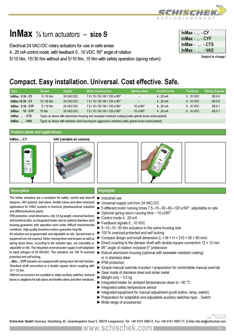
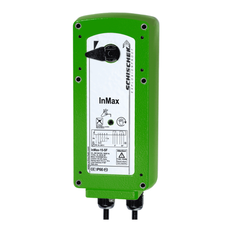
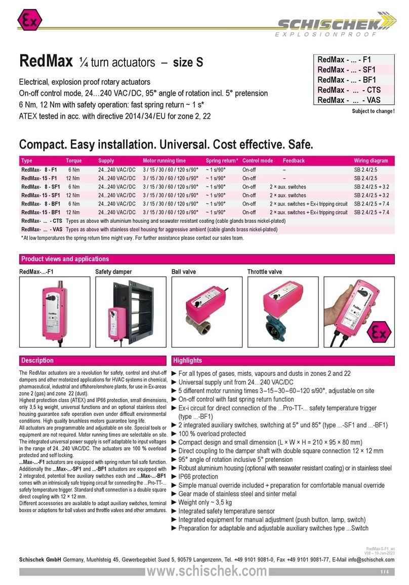
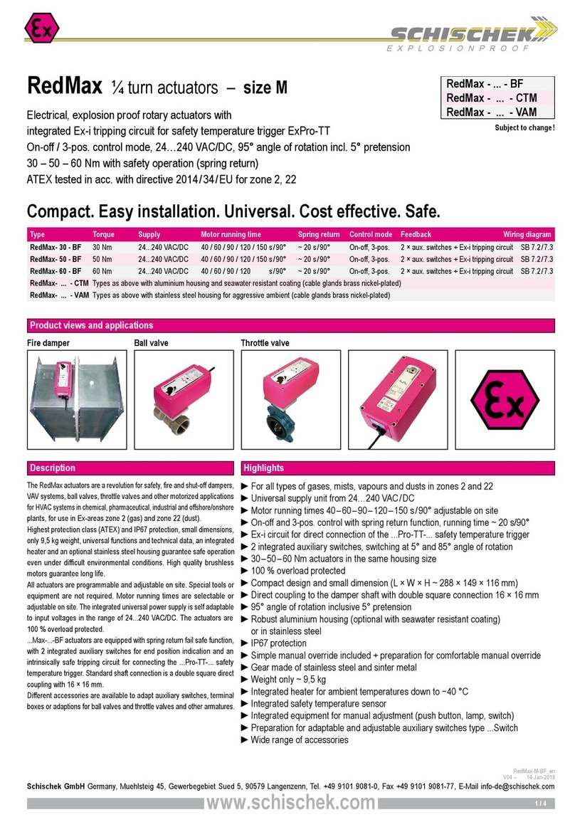
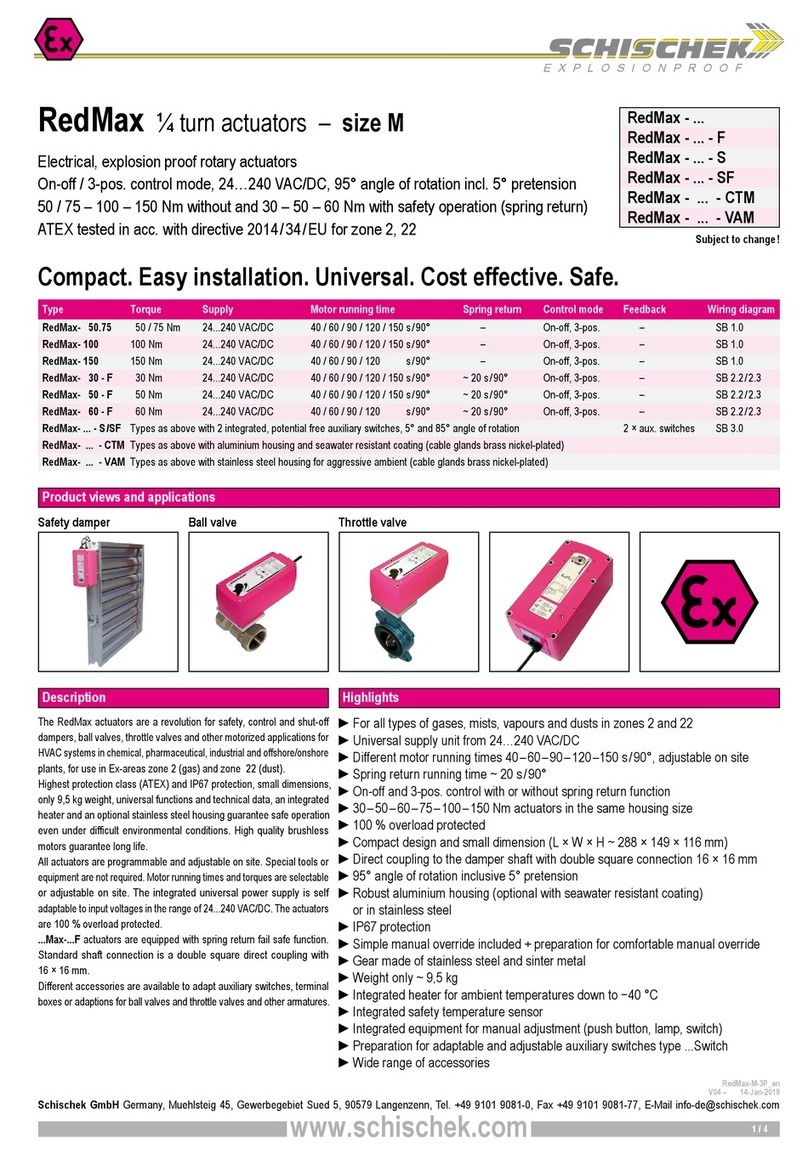
  9. Schischek EXV-8 Series User manual

Schischek EXV-8 Series User manual

EXPLOSIONPROOF
on-off
3-pos
hazardous area safe area
1
123
2 3
EXV-8230-P
230 VA
EEx-e
1324
123
56
PA
feedback-
potentiometer
PEPE
LN
205X9-01
PE
1
12 4
23
/2EE
EEx-e
132
PA
356
456
HS1 HS2
205X9-99
Aux. switch, potential free .../2EE
hazardous area safe area
PE
123
EXV-824-P
EEx-e
4
456
56
PA
feedback-
potentiometer
123
24 VA /D
132
205X9-26
on-off
3-pos
hazardous area safe area
PE
1
123
2 3
EXV-824
24 VA /D
EEx-e
1324
4
PA
205X9-25
optional
heater
on-off
3-pos
hazardous area safe area
PE
1
123
2 3
EXV-8230
230 VA
EEx-e
1324
4
PA
LN
205X9-00
optional
heater
on-off
3-pos
hazardous area safe area
subject to changepage 1 of 3
2)for steam valves:
do not mount in vertical position
w x h x d = 110 x 75 x 57 mm
2..4 x M20x1,5
EXV-...-P
EXV-...-Y
EXV-.../2EE
w x h x d = 70 x 70 X 45 mm
3 x M20x1,5
EXV-..230
EXV-....24
2)
ø 130
135
210 1)
B
A
Meassures A and B in dependance of valve type
1) for continuous actuators 233 mm
perpendicular
3
)
Mounting position EEx e terminal box
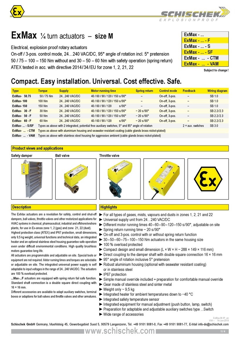
EXV-8... Valve actuators for control valve bodies or on-off function. Explosionproofed in acc. with
"flameproof enclosure" and dust ignition proof, PTB tested. Installation in hazardous areas zone 1, 2,
21, 22. The actuators are 100% overload protected and can be stopped in any position. The controller
must be stable and should not pulse. Application: For industrial plant. For Offshore applications we
recommend the special types EXV-8.../CT and EXV-8.../VA.
Valve actuator
800
Type EXV-8230 EXV-8230-P EXV-8230-Y EXV-8230-Y/I
Supply voltage ± 10% 230 V/50 Hz 230 V/50 Hz 230 V/50 Hz 230 V/50 Hz
Type EXV- 824 EXV- 824-P EXV- 824-Y EXV- 824-Y/I
Supply voltage ± 10% 24 VA /D 24 VA /D 24 VA /D 24 VA /D
Power consump. motor ~11 VA ~11 VA ~11 VA ~11 VA
Starting current capacitive load capacitive load capacitive load capacitive load
ISTART >> ITYP ISTART >> ITYP ISTART >> ITYP ISTART >> ITYP
Force ³ 800 N ³ 800 N ³ 800 N ³ 800 N
Running time ~6 sec/mm ~6 sec/mm ~6 sec/mm ~6 sec/mm
Stroke, in dep. of type 10 - 40 mm 10 - 40 mm 10 - 40 mm 10 - 40 mm
ontrol mode on-off on-off 2... 10 V 4... 20 mA
3 pos 3 pos
Input resistance 80 KW (~0,2 mA) 500 W
Feedback signal - 1000 W2... 10 V 2... 10 V
Endswitches no endswitches, actuators are overload protected
Ambient temperature 0... 40 ° , non-condensing
Housing material Aluminium baked varnish
Rod material 1.4034
Weight ~6 kg
Indication E Nr. 0158
Permission PTB-tested acc. to directive 94/9/E (ATEX)
ertificate PTB 99 ATEX 1103
Explosionproof II2G EEx d II T6, ENELE EN 50014/ EN 50018
II2D IP65 T95° , ENELE EN50281-1-1
External PE-connector onnectable lines: 4 mm2 multiple-wire, 6 mm2 single-wire
Prot. in acc. with EN 60529 IP 65
Operating mode S3 80%ED acc. to EN60034-1 minimum run time of the actuator >1 sec.
Included Actuator with 0.3m cable and protection tube, II2G/D EEx e terminal box
with mounting bracket
Installation area hazardous areas zone 1, 2, 21, 22
/K Heater for outdoor application and/or at high
humidity for reducing water condensation.
Power consumption of the heater ~16 W.
/CT All housing parts aluminium with Amercoat
varnish for Offshore applications.
/VA All housing parts in stainless steel
AISI 316 for Offshore application.
/2EE 2 integral, potential free aux. switches,
switching in end-positions.
/HV Emergency manual operation.
Adaptors different types for different valve bodies.
EXC-HSV 2 external aux. switches, potential free
contacts, each adjustable.
EXC-K/HSV EEx-Terminal box for EX -HSV.
MOL- G 24 Battery power pack, standby unit, 24V.
MOL-EH1 Electronic aux. switch, connectable to actuators
type EXV-...-Y, panel mounting.
/L16 Special Type with running time ~16 sec/mm.
 The cable of the actuator must be installed in a fixed position
and protected against mechanical damage.
 For installation, use and maintenance the official standards
and rules must be applied.
3) With horizontal installation position of the actuator, the
two spacer rods must form a vertical level.
 Temperature class T6 is only for the actuator, you have to
guarantee max. temperature of valves and tubes on site.
 The EEx actuators may only be opened by the
manufacturer to guarantee explosionproof and for
warranty.
 For outdoor installation a heater and a weather protective
housing against rain, snow and sun is required.
 After installation all componetes must fulfil the protection class
IP65 acc. EN60529.
2003/05/22
SCHISCHEK GMBH  D-90579 Langenzenn  Mühlsteig 45  Gewerbegebiet V  Tel.+49(0)9101-90810  Fax +49(0)9101-908177
 e-mail:[email protected]  Internet:http://www.schischek.com
II2G EEx d IIC T6
Zone 1, 2
II2D IP65 T95°C
Zone 21, 22
Electrical, explosionproof valve actuators Type EXV-8... List 3.0
for hazardous areas zones 1, 2, 21, 22  force 800 - tested acc. to ATEX
APPLICATIO
TECH ICAL DATA
ACCESSORIES
ELECTRICAL CO ECTIO
DIME SIO S ATTE TIO
Attention:  Voltage at terminal 2: rod is extending.
 For continuous actuators see reverse.
Ventilstellantriebe
Valve actuators
EXV-8/2024-Y
EXV-8/2024-Y/I
EXV-8/20230-Y
EXV-8/20230-Y/I
EXPLOSIONPROOF
Mounting instructions for the
valve body to the actuator EXV-...
1. The actuator will be delivered
with retracted stroke.
2. Place the actuator on the
valve body and attach with
the nuts and washers (1) provided.
3. Remove the cap nut (2) and
screw the connecting parts with
the connecting nut (3), taking
care not to damage the valve spindel.
The spindle should be retracted as
far as possible into the valve body.
4. Allow enough distance between
the threaded bolt head (4) and the
rod of the actuator, noting the travel
of the valve spindle. Any adjustment
can be done by screwing the bolt (4)
into the connection nut(3).
Tighten both counter nuts firmly.
5. Draw out the valve spindel with the
connecting parts until contact is
made to the threaded actuator rod
and join with the cap nut (2).
Do not overthighten (max. 4 m)
otherwise damage will be cause to
the mounting bracket.
6. onnect the actuator to the
supply in accordance with the
enclosed wiring diagram.
7. Operate the actuator electrically to
fully extend the actuators rod.
For modulated controlled actuator
with a 20 mA or 10 VD positioning
signal or by connecting to load via
terminal 4 (if no positioning signal available).
Visual check that the valve is closed.
Minor adjustment to the travel can be
achieved by turning the threaded bolt (4).
8. Secure all connections, take care not to
operate the actuator against the
stroke otherwise damage to
mounting bracket may occure.
9. The actuator is ready to operate.
Montage Ventilkörper an Antrieb EXV...
1. Der Antrieb wird werkseitig mit
eingefahrener Hubstange ausgeliefert!
2. Den Antrieb auf den Ventilkörper
stecken und mittels der mitgelieferten
Muttern (1) befestigen.
3. Überwurfmutter (2) lösen und
Verbindungsteile mittels der
Verbindungsmutter (3) locker auf
die Ventilspindel schrauben.
Ventilspindel dabei ganz hineindrücken!
4. Zwischen dem Schraubenkopf von
Schraube (4) und der Hubstange des
Antriebes entsprechend dem Ventilhub
Platz lassen, Ventilhub vorher messen und
notieren. Justage erfolgt über Schraube (4)
bzw. Verbindungsmutter (3).
5. Die beiden Kontermuttern (5)
handfest anziehen.
Die Ventilspindel mit den
Verbindungsteilen herausziehen und
mit Hilfe der Überwurfmutter (2) auf
der Hubstange befestigen.
icht zu fest anziehen (max. 4 m -
Zerstörung der internen Verdrehsicherung!)
6. Antrieb elektrisch nach dem Antrieb
beiliegenden Anschlußschema anschließen.
7. Antrieb elektrisch ausfahren lassen.
Bei Stetig-Antrieben mit Signal 20 mA bzw.
10 VD oder durch Auflegen der
Betriebsspannung auf Klemme 4 falls
noch kein Stellsignal vorhanden ist.
Funktion überprüfen - schließt Ventil?
Eine Nachjustage ist mittels Schraube (4) möglich.
8. Alle Verbindungen fest anziehen, dabei
darauf achten, daß nicht gegen die
Hubstange gekontert wird - Zerstörung der
internen Verdrehsicherung.
9. Der Antrieb ist betriebsbereit.
1-Mutter DIN934
Scheibe DIN125
Zahnscheibe DIN6797
2- Überwurfmutter
4-Schraube DIN912
5-Mutter DIN934
3-Verbindungsmutter
Verdrehsicherung
5-Mutter DIN934
Ventilspindel
Adapterdistanzsäule
Ventil
cap nut
threaded bolt
nut
connection nut
mounting bracket
nut
valve spindle
spacer rod
valve
nut
washer
toothed lock washer
EXV-...
Kontakt
switch
ab
Linearantrieb
linear actuator
Automatik
Automatik
Linearantrieb
linear actuator
Invers-Betrieb
reverse-function Brücke 2-4
connection 2-4
Normalbetrieb
normal function
Zwangssteuerungen
compulsion control
PE
1 2
EXV-...24-Y
EEx-e
45
PA
312
24 VA /D
36
YU
Y=2..10V
U=2..10V
4
Y
5
U
6
0
Y
1)
105X9-83
Y
Y
ba
reverse
hazardous area safe area
stetig
continuous
PE
2
EXV-...24-Y/I
EEx-e
45
PA
3
0
12
24 VA /D
136
YU
Y=4..20mA
U=2..10V
4
Y
5
U
6
Y/I
1)
105X9-76
Y
Y
ba
reverse
hazardous area safe area
stetig
continuous
PE
1 3
EXV-...230-Y
EEx-e
45
PA
312
230 VA
1236
YU
Y=2..10V
U=2..10V
4 2
U
3
7
PE
1
Y
NL
Y
1)
105X9-54
reverse
hazardous area safe area
stetig
continuous
PE
1 3
EXV-...230-Y/I
EEx-e
45
PA
312
230 VA
1236
YU
Y=4..20mA
U=2..10V
4 2
U
3
7
PE
1
Y
NL
Y/I
1)
105X9-50
reverse
hazardous area safe area
stetig
continuous
page 2 of 3
Elektrischer Anschluß "Y"oderY/I"
Electrical connection "Y"orY/I"
2003/05/22
SCHISCHEK GMBH  D-90579 Langenzenn  Mühlsteig 45  Gewerbegebiet V  Tel.+49-(0)9101-90810  Fax +49-(0)9101-908177
 e-mail:[email protected]  Internet:http://www.schischek.com
Elektrischer Anschluß
Electrical connection
Für Inversbetrieb, Brücke 2 - 4 erforderlich.
onnection 2 - 4 for reverse function.
Y-
^Y
=Stellgröße
manipulated variable
U-
^Y
=Stellungsanzeige
feedback signal
Achtung/Attention: 24 V, Y & Y/I
Masse/Ground
Die beiden Masseleitungen 0 und 1 müssen eine
galvanische Verbindung haben. Diese Verbindung
sollte sich an der Stromversorgung oder am Regler-
ausgang befinden.
The two ground lines 0 and 1 must have an electrical
connection. This connection should be made at the
power supply or the controller output.
1
) optionale Heizung / optional heating
52.5
stroke max.
40mm
Kabel
100(80)
310
233 -EXV-...230Y
Ø34
Ø130
(285) 233 -EXV-...24Y
(208 -EXV-...24)
(208 -EXV-...230)
Klemmkasten EEx e II T6
terminal enclosures
cable
14
M16x1.5
2 x Gewinde M8 x 10
Aufnahme-Distanzsäule
2 x thread M8 x 10
mounting-adapter bar
EXPLOSIONPROOF
page 3 of 3
72±1
Valve actuator
800
2003/05/22
SCHISCHEK GMBH  D-90579 Langenzenn  Mühlsteig 45  Gewerbegebiet V  Tel.+49-(0)9101-90810  Fax +49-(0)9101-908177
 e-mail:[email protected]  Internet:http://www.schischek.com
Electrical, explosionproof valve actuators Type EXV-8... List 3.0
for hazardous areas zones 1, 2, 21, 22  force 800 - tested acc. to ATEX EX-VE T
DRAWI G

This manual suits for next models

8

Other Schischek Controllers manuals

Schischek ExMax-50.75 Owner's manual

Schischek

Schischek ExMax-50.75 Owner's manual

Schischek ExReg-V CT Series User manual

Schischek

Schischek ExReg-V CT Series User manual

Schischek ExMax CTM Series User manual

Schischek

Schischek ExMax CTM Series User manual

Schischek RedMax F1 Series User manual

Schischek

Schischek RedMax F1 Series User manual

Schischek ExRun Y Series User manual

Schischek

Schischek ExRun Y Series User manual

Schischek RedMax S Series User manual

Schischek

Schischek RedMax S Series User manual

Schischek InMax Series User manual

Schischek

Schischek InMax Series User manual

Schischek RedMax-30-BF User manual

Schischek

Schischek RedMax-30-BF User manual

Schischek ExMax Series Quick start guide

Schischek

Schischek ExMax Series Quick start guide

Schischek InMax SF3 Series User manual

Schischek

Schischek InMax SF3 Series User manual

Schischek ExMax CTM Series User manual

Schischek

Schischek ExMax CTM Series User manual

Schischek RedMax F Series User manual

Schischek

Schischek RedMax F Series User manual

Schischek ExMax F3 Series User manual

Schischek

Schischek ExMax F3 Series User manual

Schischek ExMax BF User manual

Schischek

Schischek ExMax BF User manual

Schischek Redmax Series Quick start guide

Schischek

Schischek Redmax Series Quick start guide

Schischek InMax-100 User manual

Schischek

Schischek InMax-100 User manual

Schischek RedMax BF Series User manual

Schischek

Schischek RedMax BF Series User manual

Schischek InMax-8-F1 User manual

Schischek

Schischek InMax-8-F1 User manual

Schischek InMax-8-F1 User manual

Schischek

Schischek InMax-8-F1 User manual

Schischek InMax CTM Series User manual

Schischek

Schischek InMax CTM Series User manual

Schischek RedMax CTM Series User manual

Schischek

Schischek RedMax CTM Series User manual

Schischek ExMax CTS Series User manual

Schischek

Schischek ExMax CTS Series User manual

Schischek ExMax User manual

Schischek

Schischek ExMax User manual

Schischek RedMax-Y Series User manual

Schischek

Schischek RedMax-Y Series User manual

Popular Controllers manuals by other brands

Siemens SITRANS LUT400 operating instructions

Siemens

Siemens SITRANS LUT400 operating instructions

GO2 RH1 operating instructions

GO2

GO2 RH1 operating instructions

Kyocera N datasheet

Kyocera

Kyocera N datasheet

Mesto QUADRA-POWR X Installation maintenance and operating instructions

Mesto

Mesto QUADRA-POWR X Installation maintenance and operating instructions

dji N3 quick start guide

dji

dji N3 quick start guide

Chino KP 2000 Series instructions

Chino

Chino KP 2000 Series instructions

Grow K216 user manual

Grow

Grow K216 user manual

IWAKI AMERICA Walchem W900 Quick programming guide

IWAKI AMERICA

IWAKI AMERICA Walchem W900 Quick programming guide

Renogy Commander Series manual

Renogy

Renogy Commander Series manual

Belimo SY U24-SR Series Wiring diagram

Belimo

Belimo SY U24-SR Series Wiring diagram

Jamara CR40EP Instruction

Jamara

Jamara CR40EP Instruction

HID VertX EVO V1000 installation guide

HID

HID VertX EVO V1000 installation guide

Deltran Battery Tender 030-2040-WH instruction manual

Deltran

Deltran Battery Tender 030-2040-WH instruction manual

Telwin DRIVE 9000 instruction manual

Telwin

Telwin DRIVE 9000 instruction manual

Furman M-8x AR instructions

Furman

Furman M-8x AR instructions

Danfoss VLT Decentral FCD 300 Service manual

Danfoss

Danfoss VLT Decentral FCD 300 Service manual

Computer Automation Technology CAT-300 manual

Computer Automation Technology

Computer Automation Technology CAT-300 manual

LEGRAND Arteor quick start guide

LEGRAND

LEGRAND Arteor quick start guide

manuals.online logo
manuals.online logoBrands
  • About & Mission
  • Contact us
  • Privacy Policy
  • Terms and Conditions

Copyright 2025 Manuals.Online. All Rights Reserved.