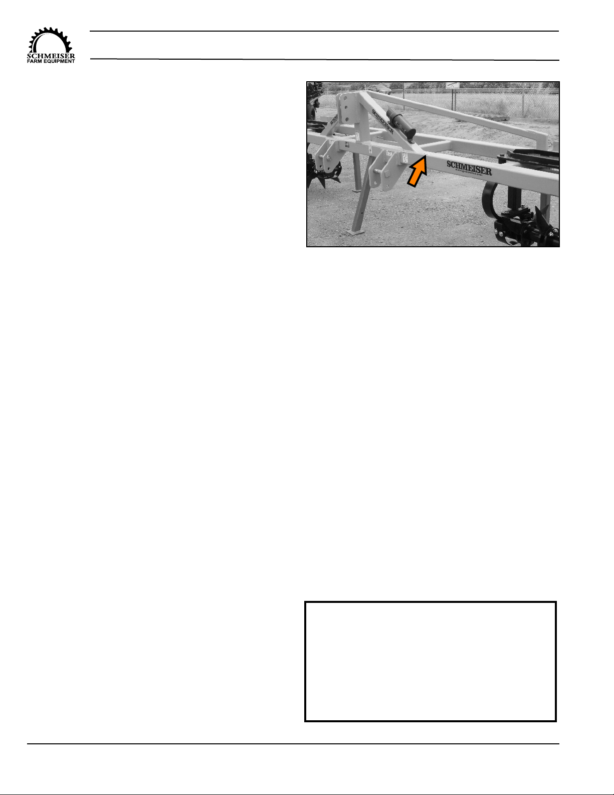
Smart-Till Orchard MaxT.G. Schmeiser Co., Inc.
Ph. (559) 268-8128
Fax (559) 268-3279
www.tgschmeiser.com
7
NO PASSENGERS ALLOWED
Do not carry passengers
anywhere on or in the tractor or
implement .
Read and Understand Manual
To prevent personal injury or even death, be sure
you read and understand all of the instructions in
this manual and other related OEM equipment manuals!
This equipment is dangerous to children and persons
unfamiliar with its operation . The operator should be a
responsible adult familiar with farm machinery and
trained in this equipment’s operations . Do not allow
persons to operate or maintain this unit until they have
read this manual and have developed a thorough
understanding of the safety precautions and how it
works .
This unit was designed for a specific application;
DO NOT modify or use this unit for any application other
than that for which it was designed .
Units operated improperly or by untrained personnel
can be dangerous!
GENERAL SAFETY
Fall Hazard
Do not use this implement as a work
platform . Do not stand on top of the unit at
any time . Do not ride on the tractor or the implement or
allow others to ride .
Crush Hazard
(Rolling Over)
To prevent serious
injury or death, before disconnecting, leaving the
operator’s seat, servicing, adjusting, repairing, or
performing other work on the implement, ALWAYS:
1 . Stop the tractor or towing vehicle .
2 . Shut off the engine and remove the ignition key .
3 . Set the brakes .
4 . Make sure wheel cylinder transport lock is
attached .
5. Relieve hydraulic fluid pressure.
STOP
0
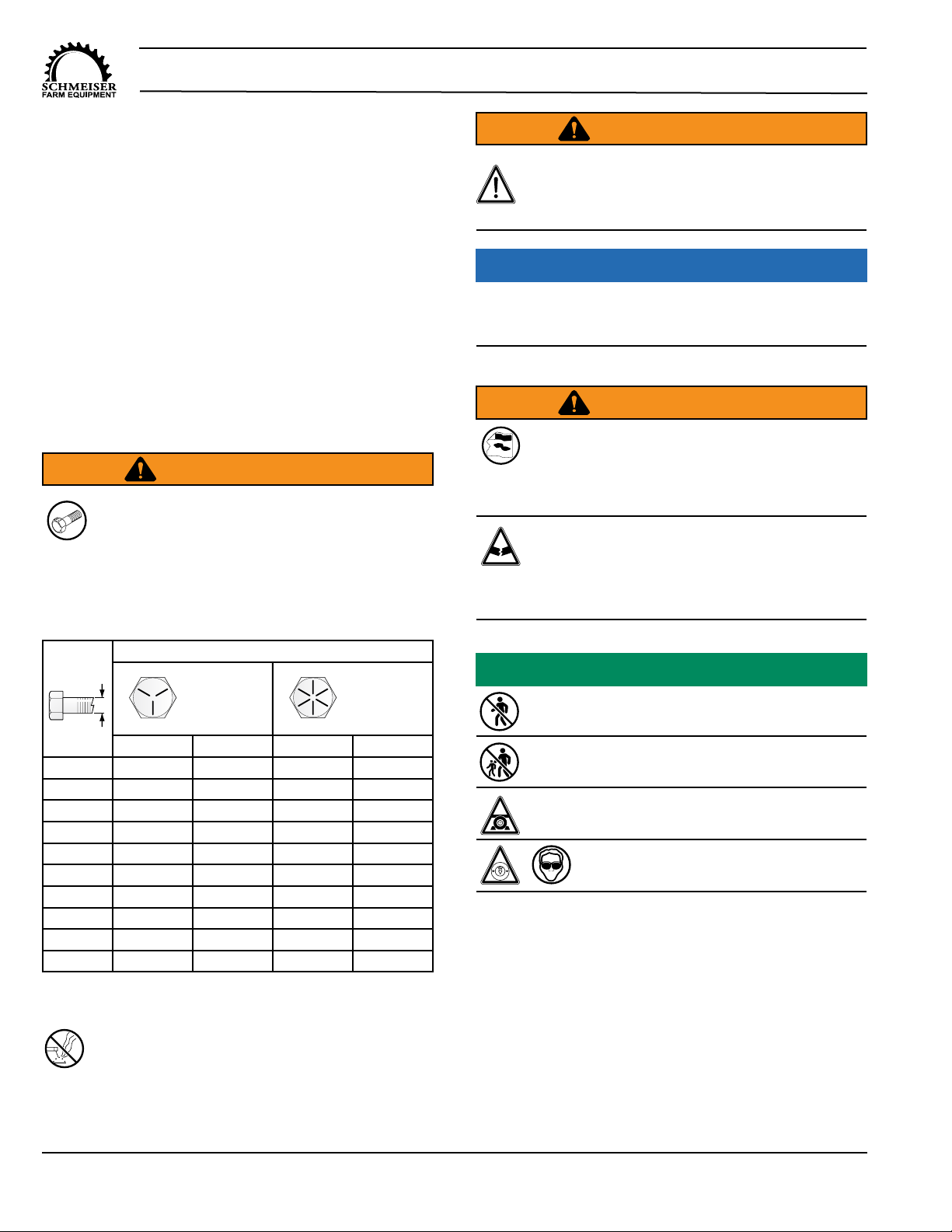
ASSEMBLY SAFETY
Crush Hazard
Use support blocks or safety stands
rated to support the load when
assembling the unit or performing maintenance .
Never work under equipment supported by hydraulics .
Hydraulics can drop equipment instantly if controls are
actuated even when power to the hydraulics is shut off .
To prevent injury, use a tractor equipped with a
Roll Over Protective System (ROPS) .
Visually Inspect
Visually inspect the unit for any loose bolts,
worn parts, or cracked welds, and make
necessary repairs before using the unit .
Rolling Hazard
To prevent serious injury, lock the wheels when
performing assembly, maintenance, repairs, or
when preparing for storage.
Personal Protection Equipment
When working around or operating this unit, wear
appropriate personal protective equipment . This list
includes but is not limited to:
• A hard hat
• Protective shoes with slip resistant soles
• Protective goggles, glasses, or face shield
• Heavy gloves and protective clothing
• Ear muffs or plugs
Use Properly Rated Tools
To prevent serious injury:
Use sufficient tools, jacks, and hoists
that have the capacity for the job .
Trapped Air Hazard
When installing, replacing, or repairing hydraulic
system cylinders or parts, make sure that the
entire system is charged and free of air before resuming
operations . Failure to bleed the system of all air can
result in improper machine operation, causing severe
injury .
Injury Hazard
Do not permit children to play on or around the
unit .
Impaired Operator Hazard
Do not attempt to operate this unit under the
influence of drugs or alcohol. Review the
safety instructions with all users annually .
Pinch Point /Sharp Object Hazard
Do not place any body parts between moving and /
or stationary parts . The weight of the implement will
easily cause serious bodily injury.