Schmeiser Varitrak SVT-16R Guide

SCHMEISER
VARITRAK
OPERATION AND PARTS
MANUAL
T. G. SCHMEISER Co., Inc.
Read and understand the manual. This manual provides information and procedures to
safely operate and maintain the Varitrak.
Version 2.0
September

Copyright © 2019 T. G. Schmeiser Co., Inc. All rights reserved

VaritrakT.G. Schmeiser Co., Inc.
Ph. (559) 268-8128
Fax (559) 268-3279
www.tgschmeiser.com
3
Adjust Wing Turnbuckle............................20
Calibrate Wing Linkage.............................20
Initial Setup Checklist.........................................21
Implement Break-In............................................21
Connecting to Tractor.........................................21
Detaching from Tractor.......................................21
Field Operation...................................................22
Operation with a Laser System.................22
When Transporting Varitrak on the Road...........23
MAINTENANCE.......................................................23
Lubrication Points...............................................23
Wheel Hub Bearings.................................23
Wing Linkage.............................................23
Service Items......................................................24
Hydraulic Cylinders...................................24
Hydraulic Hoses........................................24
Front 3-Pt. Linkage....................................24
Tires...........................................................24
Ground Engaging Components..........................24
Bucket Blade.............................................24
S-Tines......................................................24
Maintenance Schedule.......................................25
STORAGE................................................................26
Storage Preparation...........................................26
Placing in storage...............................................26
Removing From Storage....................................26
PARTS SECTION.....................................................27
Component Nomenclature..................................27
Ordering Parts....................................................28
Parts Drawings...............................................28
Self-Leveling 3-Pt. Hitch Assembly...........28
3-Pt. Hitch Laser Option Assembly............29
Wing Linkage and Turnbuckle Assembly...30
Sliding Plates Assembly............................31
Dual Tire Frame Assembly........................32
Single Tire/Steel Wheel Frame Assembly..33
Wing Bucket Assembly..............................34
Rear Braces Assembly..............................35
S-Tine Attachment Assembly (Optional)...36
S-Tine Attachment Links Assembly (Opt.).37
S-Tine Assembly (Optional)......................38
S-Tine Layouts (Optional)..........................39
HYDRAULIC DIAGRAMS.........................................40
LIMITED WARRANTY STATEMENT.......................43
CONTENTS
INTRODUCTION........................................................4
Engineered for Long Life...................................4
Serial Number Information....................................4
Replacement Parts................................................4
Warranty Information............................................4
Serial Number Location.........................................4
Factory Contact Information..................................4
Dealer Contact Information....................................4
SPECIFICATIONS......................................................5
SAFETY......................................................................6
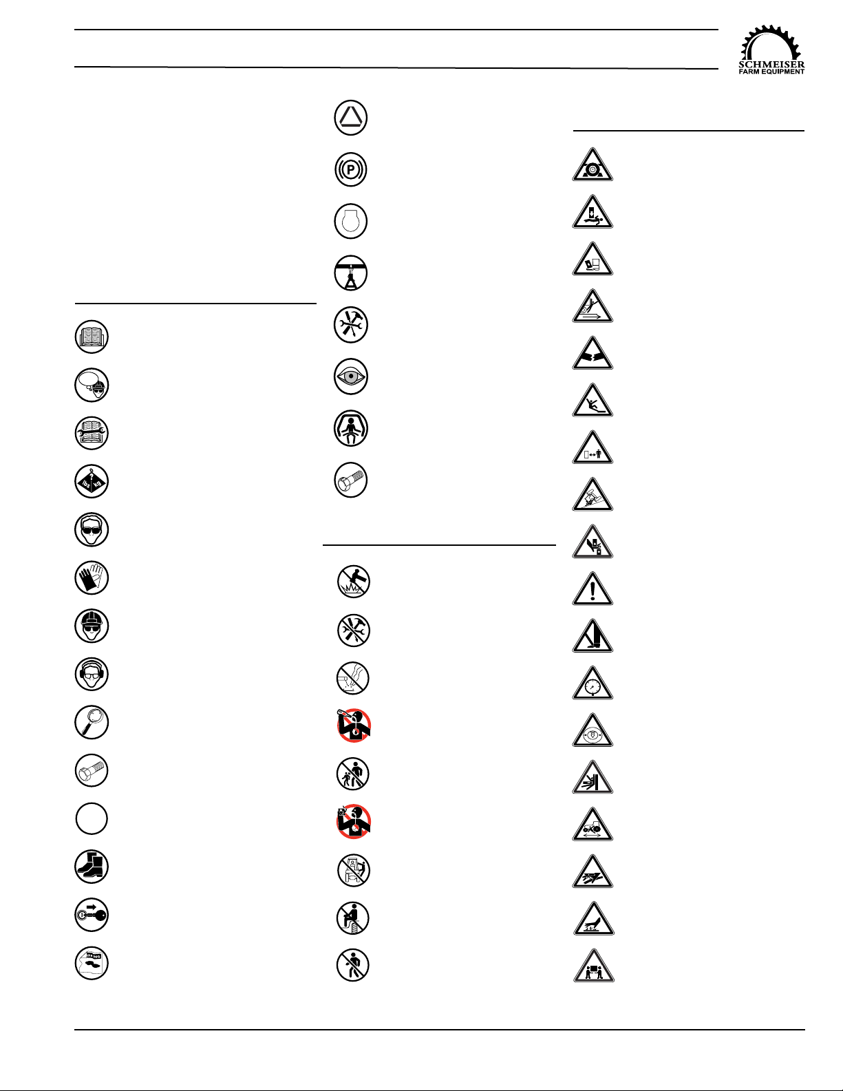
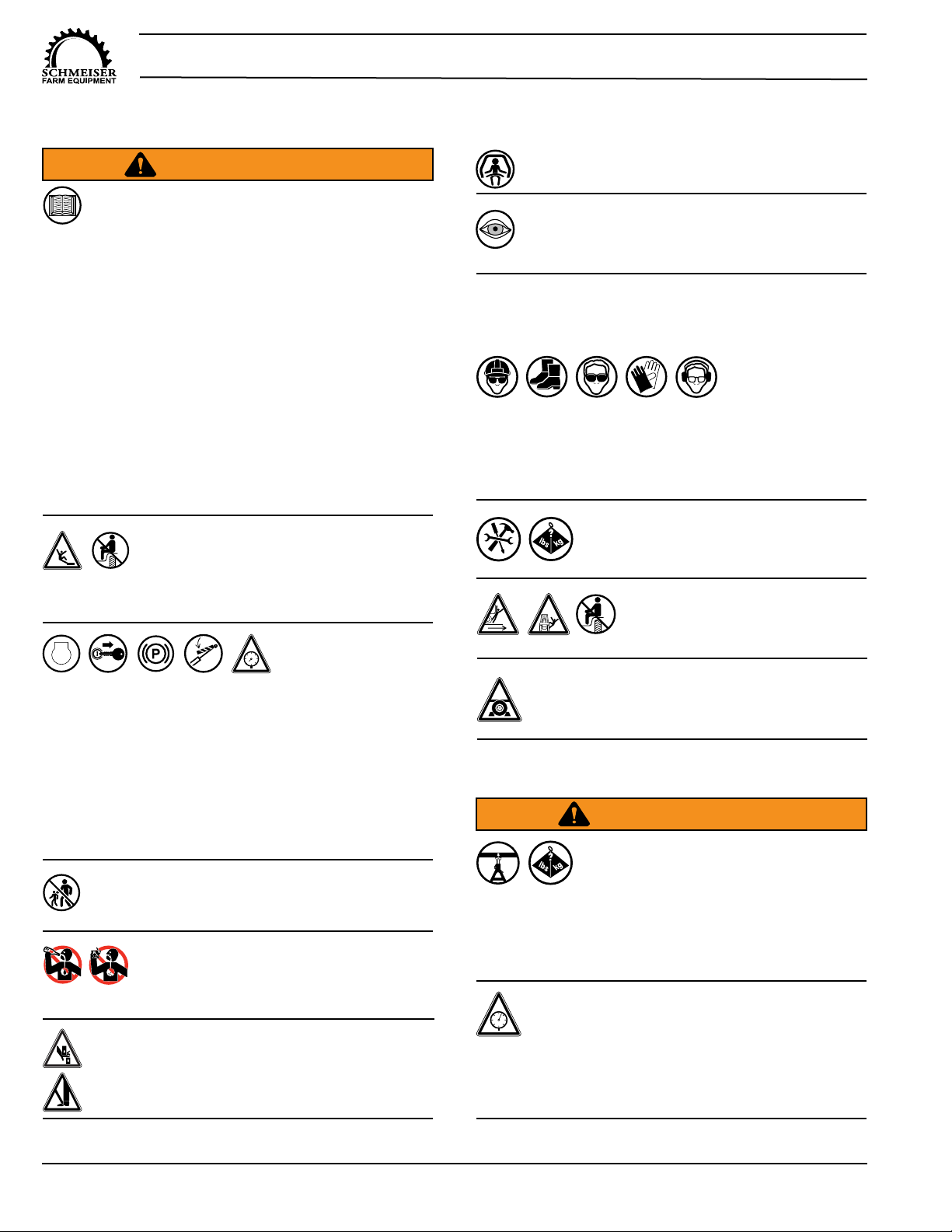
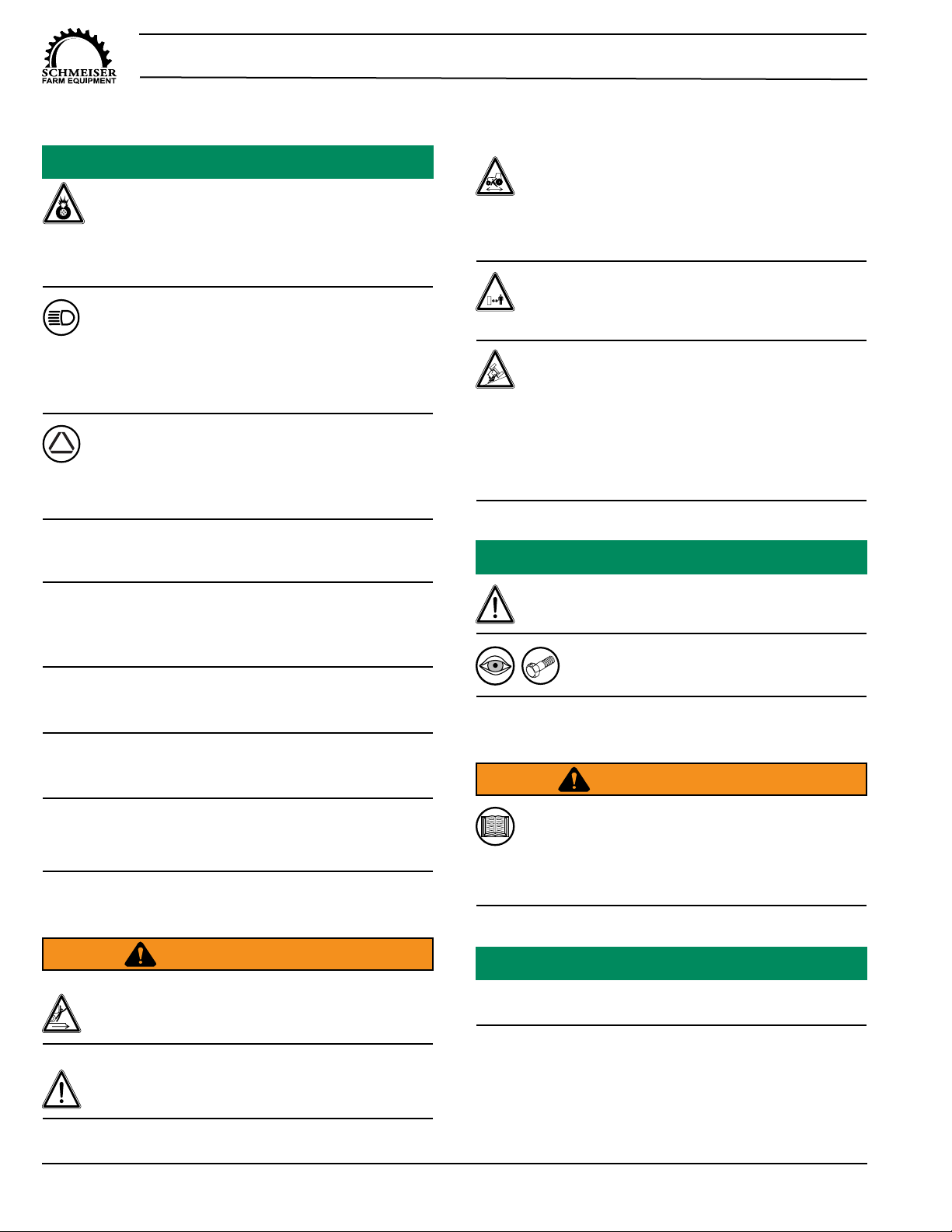
Safety Alert Symbols............................................6
Safety Icons Nomenclature..................................7
Personal Protection/Important Information..7
Prohibited Actions........................................7
Hazard Avoidance.......................................7
General Safety......................................................8
Assembly Safety...................................................8
Towing Safety.......................................................9
Highway and Transport Operations..........10
Operation Safety.................................................10
Tractor Requirements................................10
Tractor Safety Devices..............................11
ROPS and Seat Belt..................................11
Attaching to Tractor............................................11
Prior to Connecting Unit ............................11
Connecting to the Tractor..........................11
Hydraulic Component Safety..............................12
Maintenance Safety............................................12
Tires Safety...............................................13
Tire and Lug Torque Specifications...........13
Bolt Torque Requirements.........................13
Welding Repairs........................................14
Storage Safety...................................................14
Disposal of Equipment at End of Useful Life......14
Safety Marking and Lighting...............................15
SAFETY SIGNS AND DECALS...............................16
Safety Sign Placement....................................16
Safety Signs and Decals.....................................17
ASSEMBLY AND OPERATION...............................18
Assembly Procedure...........................................18
Self-Leveling Hitch.................................18
Laser Control Kit (Optional)..................19
S-Tine Assembly (Optional)..................19
Adjustment Procedure.......................................20
Level Wings..............................................20

Varitrak T.G. Schmeiser Co., Inc.
Ph. (559) 268-8128
Fax (559) 268-3279
www.tgschmeiser.com 4
INTRODUCTION
Your Schmeiser Varitrak (implement) is designed to
provide many years of dependable service. This manual
has been prepared to instruct the user in the safe and
efficient operation of this implement. Read and
understand the manual thoroughly and follow all
instructions carefully.
Engineered for Long Life
The Varitrak levels, smoothes, pulverizes the soil, fills
depressions, and packs it all in one operation, helping
save time and money. The Varitrak is extremely
maneuverable in open field and orchard applications.
Serial Number Information
Record the serial number, model number, and date
purchased in the space provided in the Serial Number
Location section. Be sure to have this information
whenever contacting the dealer to order parts or
attachments for this implement.
Replacement Parts
Should this implement require replacement parts,
contact your local Schmeiser dealer. Always order
genuine Schmeiser OEM replacement parts.
Warranty Information
It is important that the Warranty Card be completed and
sent to Schmeiser. The warranty will not be valid until
the information is on-file at Schmeiser. If information
not contained in this manual is needed, contact your
Schmeiser dealer.
Thank you for buying a Schmeiser Varitrak.
Serial Number Location
Serial No. __________________________________
Model No. __________________________________
Date Purchased. _____________________________
Dealer Name. _______________________________
Factory Contact Information
For questions not answered in this manual, if additional
copies are required, or the manual is damaged, please
contact your local dealer or:
T. G. Schmeiser Co., Inc.
P.O. Box 1392
Selma, CA 93662
Phone: (559) 268-8128
Fax: (559) 268-3279
E-mail: sales@tgschmeiser.com
Web: www.tgschmeiser.com
Additional copies of this manual can also be downloaded
at www.tgschmeiser.com.
Dealer Contact Information
For replacement decals, questions, or to order parts,
contact your dealer:

VaritrakT.G. Schmeiser Co., Inc.
Ph. (559) 268-8128
Fax (559) 268-3279
www.tgschmeiser.com
5
SPECIFICATIONS
Model Number Bucket Width Rear Track Weight
SVT-16R 16 Ft. (4.9 m)
Min. 9.0 Ft. (2.7 m)
Max. 16.0 Ft. (4.9 m)
3600 lbs. (1633 kg)
SVT-16S 16 Ft. (4.9 m)
Min. 9.6 Ft. (3.0 m)
Max. 16.0 Ft. (4.9 m)
3920 lbs. (1778 kg)
SVT-20R 20 Ft. (6.0 m)
Min. 9.0 Ft. (2.7 m)
Max. 16.0 Ft. (4.9 m)
4440 lbs. (2011 kg)
SVT-20S 20 Ft. (6.0 m)
Min. 9.6 Ft. (3.0 m)
Max. 16.0 Ft. (4.9 m)
4760 lbs. (2156 kg)
SVT-24R 24 Ft. (7.3 m)
Min. 9.0 Ft. (2.7 m)
Max. 16.0 Ft. (4.9 m)
4587 lbs. (2078 kg)
SVT-24S 24 Ft. (7.3 m)
Min. 9.6 Ft. (3.0 m)
Max. 16.0 Ft. (4.9 m)
4907 lbs. (2223 kg)
SVT-30R 30 Ft. (9.1 m)
Min. 9.0 Ft. (2.7 m)
Max. 16.0 Ft. (4.9 m)
4812 lbs. (2182 kg)
SVT-30S 30 Ft. (9.1 m)
Min. 9.6 Ft. (3.0 m)
Max. 16.0 Ft. (4.9 m)
5132 lbs. (2328 kg)
Horsepower
SVT-16R SVT-20R SVT-24R SVT-30R
Minimum Drawbar
110 (82 kW) 130 (97 kW) 150 (112 kW) 190 (140 kW)
Recommended
Drawbar 125 (93 kW) 150 (112 kW) 180 (134 kW) 200 (147 kW)
HP requirements for crawlers rated at 65% of above.
HP requirements for 4-wheel drive tractors rated at 85% of above.

Varitrak T.G. Schmeiser Co., Inc.
Ph. (559) 268-8128
Fax (559) 268-3279
www.tgschmeiser.com 6
Carefully read and follow all safety precautions before
operation. There are obvious and hidden potential
hazards involved in the operation of this implement.
Serious injury or death may occur unless care is
taken to ensure the safety of both the operator and
any other persons in the area. Avoid potential danger
by taking extra time for thought and a more careful
approach to the use of this implement.
Most work related accidents are caused by failure to
observe basic safety rules or precautions. An
accident can often be avoided by recognizing
potentially hazardous situations before an accident
occurs. As you assemble, operate, or maintain the
unit, you must be alert to potential hazards. You
should also have the necessary training, skills, and
tools to perform any assembly or maintenance
procedures.
Improper operation and maintenance of this unit could
result in a dangerous situation that could cause injury
or death. T.G. Schmeiser cannot anticipate every
possible circumstance that might involve a potential
hazard. The warnings in this manual and on the
product are, therefore, not all-inclusive. If a method of
operation not specifically recommended by us is
used, you must satisfy yourself that it is safe for you
and for others. You should also ensure that the unit
will not be damaged or be made unsafe by the
methods that you choose.
The information, specifications, and illustrations in this
manual are based on the information that was
available at the time this material was written and are
subject to change without notice.
Safety Alert Symbols
This is the safety alert symbol. It is used to
alert you to potential personal injury
hazards.
Obey all safety messages that follow this
symbol to avoid possible injury or death.
This manual contains DANGERS, SAFETY
INSTRUCTIONS, CAUTIONS, IMPORTANT NOTICES,
and NOTES which must be followed to prevent the
possibility of improper service, damage to the equipment,
personal injury, or death. The following key words call the
readers attention to potential hazards.
Hazards are identified by the “Safety Alert Symbol” and
followed by a signal word such as “DANGER”,
“WARNING”, or “CAUTION”.
DANGER
Indicates an imminently hazardous situation which,
if not avoided, will result in death or serious injury .
This signal word is limited to the most extreme
situations .
Indicates a potentially hazardous situation which, if
not avoided, could result in death or serious injury .
CAUTION
Indicates a potentially hazardous situation which, if
not avoided, may result in minor or moderate injury.
Indicates that equipment or property damage can
result if instructions are not followed.
NOTICE
Safety instructions (or equivalent) signs indicate
specific safety-related instructions or procedures.
SAFETY INSTRUCTIONS
Note: Contains additional information important to a
procedure.
SAFETY
WARNING

VaritrakT.G. Schmeiser Co., Inc.
Ph. (559) 268-8128
Fax (559) 268-3279
www.tgschmeiser.com
7
Safety Icons Nomenclature
This manual and the equipment has
numerous safety icons.
These safety icons provide
important operating instructions
which alert you to potential personal
injury hazards.
READ THE MANUAL
THINK
SAFETY! THINK SAFETY
MAINTENANCE
PROCEDURE
WEIGHT RATING
HAND PROTECTION
HEAD PROTECTION
HEARING PROTECTION
INSPECT EQUIPMENT
N
PLACE IN NEUTRAL
PROTECTIVE SHOES
REMOVE KEY
EYE PROTECTION
DAMAGED HAZARD
LABEL
OEM PARTS ONLY
OEM
SET PARKING BRAKE
SLOW VEHICLE PLACARD
STOP STOP ENGINE
Prohibited Actions
SUPPORT STAND USAGE
USE PROPER TOOLS
VISUALLY INSPECT
USE ROPS
USE CORRECT PARTS
DO NOT ALTER OR MODIFY
DO NOT LEAVE OUT TOOLS
DO NOT WELD
NO ALCOHOL
NO CHILDREN
NO DRUGS
NO BYSTANDERS
NO RIDERS
NO PASSENGERS
CRUSHING HAZARD (body)
CRUSHING HAZARD (foot)
CRUSH HAZARD (rolling over)
DEFECTIVE OR BROKEN PART
FALLING HAZARD
MAINTAIN SAFE DISTANCE
OVERTURN HAZARD
PINCH POINT HAZARD
SAFETY ALERT SYMBOL
SHARP OBJECT HAZARD
0ZERO PRESSURE
COMPRESSED AIR HAZARD
CRUSH HAZARD
CRUSH HAZARD
BLOCK WHEELS
HIGH PRESSURE
FLUID HAZARD
HOT SURFACE HAZARD
HEAVY OBJECT HAZARD
Personal Protection/Important
Information
Hazard Avoidance

Varitrak T.G. Schmeiser Co., Inc.
Ph. (559) 268-8128
Fax (559) 268-3279
www.tgschmeiser.com 8
NO PASSENGERS ALLOWED
Do not carry passengers
anywhere on or in the tractor or
implement .
Read and Understand Manual
To prevent personal injury or even death, be
sure you read and understand all of the
instructions in this manual and other related OEM
equipment manuals! This equipment is dangerous to
children and persons unfamiliar with its operation . The
operator should be a responsible adult familiar with
farm machinery and trained in this equipment’s
operations . Do not allow persons to operate or
maintain this unit until they have read this manual and
have developed a thorough understanding of the
safety precautions and how it works .
This unit was designed for a specific application;
DO NOT modify or use this unit for any application
other than that for which it was designed .
Units operated improperly or by untrained personnel
can be dangerous!
WARNING
GENERAL SAFETY
Fall Hazard
Do not use this implement as a work
platform . Do not stand on top of the
unit at any time . Do not ride on the tractor or the
implement or allow others to ride .
Crush Hazard
(Rolling Over)
To prevent serious
injury or death, before disconnecting, leaving the
operator’s seat, servicing, adjusting, repairing, or
performing other work on the implement, ALWAYS:
1 . Stop the tractor or towing vehicle .
2 . Shut off the engine and remove the ignition key .
3 . Set the brakes .
4 . Make sure wheel cylinder transport lock is
attached .
5. Relieve hydraulic fluid pressure.
STOP
0
ASSEMBLY SAFETY
Crush Hazard
Use support blocks or safety stands
rated to support the load when
assembling the unit or performing maintenance .
Never work under equipment supported by hydraulics
. Hydraulics can drop equipment instantly if controls
are actuated even when power to the hydraulics is
shut off .
To prevent injury, use a tractor equipped with
a Roll Over Protective System (ROPS) .
Visually Inspect
Visually inspect the unit for any loose bolts,
worn parts, or cracked welds, and make
necessary repairs before using the unit .
Rolling Hazard
To prevent serious injury, lock the wheels when
performing assembly, maintenance, repairs, or
when preparing for storage.
Personal Protection Equipment
When working around or operating this unit, wear
appropriate personal protective equipment . This list
includes but is not limited to:
• A hard hat
• Protective shoes with slip resistant soles
• Protective goggles, glasses, or face shield
• Heavy gloves and protective clothing
• Ear muffs or plugs
Use Properly Rated Tools
To prevent serious injury:
Use sufficient tools, jacks, and hoists
that have the capacity for the job .
Trapped Air Hazard
When installing, replacing, or repairing
hydraulic system cylinders or parts, make
sure that the entire system is charged and free
of air before resuming operations . Failure to bleed
the system of all air can result in improper machine
operation, causing severe injury .
WARNING
Injury Hazard
Do not permit children to play on or around the
unit .
Impaired Operator Hazard
Do not attempt to operate this unit under
the influence of drugs or alcohol. Review
the safety instructions with all users annually .
Pinch Point /Sharp Object Hazard
Do not place any body parts between moving
and / or stationary parts . The weight of the
implement will easily cause serious bodily injury.

VaritrakT.G. Schmeiser Co., Inc.
Ph. (559) 268-8128
Fax (559) 268-3279
www.tgschmeiser.com
9
TOWING SAFETY
WARNING
Unexpected Separation Hazard
If the safety chain does not have a current
certification tag, do not use the unit until
properly certified chains are installed. Substandard
safety chains could allow the unit to separate from
the tow vehicle, resulting in equipment damage and
personal injury .
Loss of Control
A minimum of 20% of the combined tractor
and equipment weight should be on the front
wheels to ensure adequate stability during transport
and operation . To avoid serious injury or death from
a loss of control accident, maintain 20% weight on
the front wheels . Add front end weight if necessary .
SAFETY INSTRUCTIONS
Towing the implement requires care! Both the
implement and tow vehicle must be in good
working condition . Securely attach the unit to
the tow vehicle using a high strength, appropriately
sized hitch pin with a mechanical retainer and attach
the safety chain .
Hitch and coupling on the towing vehicle must
be rated equal to, or greater than, the unit’s
“gross vehicle weight rating” (GVWR) .
Check the tires for tread wear, inflation
pressure, and overall condition before towing
the unit .
Inspect the hitch and coupling for wear or
damage . DO NOT tow the unit using a defective
hitch or coupling!
Make sure the lug nuts holding the wheels are
tight (torque to specifications) and that none
are missing .
Do not allow anyone to stand between the
tongue or hitch and the towing vehicle when
backing up to the unit .
Operate the towing vehicle from the operator’s seat
only .
Be aware of physical surroundings and
especially bystanders, particularly children,
before moving the unit! This is particularly
important with higher noise levels and quiet cabs, as
you may not hear people shouting .
Always operate equipment in a position to provide
maximum visibility at all times . Make allowances for
increased length and weight of the equipment when
making turns, stopping, etc .
Watch for overhead obstructions and side clearances
while transporting .
Always keep the tractor or towing vehicle in gear to
provide engine braking when going downhill . Do not
coast .
Avoid sudden uphill turns on steep slopes .
Reduce speed prior to turns to avoid the risk of
overturning .
Always drive at a safe speed relative to local conditions,
and ensure that your speed is low enough for an
emergency stop to be safe and secure . Keep speed to a
minimum .
Never use independent braking with unit in tow as
loss of control and/or upset of unit may result .
When transporting, remember the implement may
be wider than your tractor and extreme care must
be taken to allow for safe clearance .

Varitrak T.G. Schmeiser Co., Inc.
Ph. (559) 268-8128
Fax (559) 268-3279
www.tgschmeiser.com 10
Tractor Requirements
Highway and Transport Operations
Make sure the wheel lift cylinder transport locks are
installed, and the jack stand is in its storage position
before transporting the unit .
Be observant of bridge load restrictions . Do not cross
bridges rated lower than the gross weight at which you
are operating .
Be a safe and courteous driver . Always yield to
oncoming traffic in all situations, including narrow
bridges, intersections, etc . Plan your route to avoid
heavy traffic.
Some localities prohibit the use of flashing amber
lights . Local laws should be checked for all highway
lighting and marking requirements .
When towing the unit on public roads, use
flashing amber warning lights and a slow moving
vehicle (SMV) identification emblem.
Make sure the SMV placard is clearly visible to vehicles
approaching from the rear .
When transporting the implement on public
roads, use approved accessory lighting, flags, or
other necessary warning devices to protect
operators of other vehicles on the highway
during daytime and nighttime transport . Various safety
lights and devices are available from your dealer .
Do not exceed a towing speed of more than
20 mph (32 KPH) on a public roadway .
Tires supplied by the manufacturer are designed to
operate NO MORE THAN 20 mph . Do not exceed the
maximum speed or tire failure may occur .
SAFETY INSTRUCTIONS
When transporting the implement on rough or uneven
surfaces, drive slowly to prevent bouncing and loss of
contact of the front wheels and the ground .
OPERATION SAFETY
WARNING
Crush Hazard (Rolling Over)
Do not clean, lubricate, or make adjustments
while the unit is moving .
Never allow inexperienced or untrained
personnel to operate the implement or tractor
without supervision .
Enter And Exit Tractor
To avoid being run over, do not enter or exit
tractor when it is moving . Avoid serious
injury or death, from contact with rotating tires, by
entering or exiting tractor only when it is completely
stopped .
Safe Distance
Keep all bystanders, especially children,
away from the tractor and implement during
operation .
Overturn Hazard
Pick the most level route possible when
transporting across fields. Avoid the edges of
ditches, gullies, or steep hillsides .
Be especially careful when turning on slopes with
the wheels down . Never turn uphill with the wheels
down except at slow speed and a low rate of turn .
Never transport or operate this machine on steep
slopes .
Periodically clear the unit of brush, twigs, or other
materials to prevent buildup of dry, combustible
materials .
Visually check all fasteners for tightness
or damage before and after operation .
Repair immediately if required .
SAFETY INSTRUCTIONS
Tractor Owner/Operator Manual
Always refer to the tractor Operator’s Manual
to ensure compatibility and maximum safety .
Be familiar with the location, settings, and function of
the tractor controls before using this equipment .
WARNING
SAFETY INSTRUCTIONS
Do not use a tractor of more than the recommended HP
to prevent damaging implement components.

VaritrakT.G. Schmeiser Co., Inc.
Ph. (559) 268-8128
Fax (559) 268-3279
www.tgschmeiser.com
11
If transporting or operating the tractor and implement
near a public roadway, the tractor must be equipped
with proper warning lighting and a Slow Moving Vehicle
(SMV) emblem, which are clearly visible from the rear of
the unit. Lights and a SMV emblem must be attached
directly to the implement if the visibility of the tractor
warning signals is obscured.
Never operate the tractor PTO with the PTO master
shield missing or in the raised position.
Rollover Hazard
To avoid serious injury or death from
falling off tractor, equipment runover,
rollover, or crushing:
1) Use ROPS equipped tractor .
2) Keep ROPS locked in the UP position .
3) Only operate the equipment when seated in the
tractor seat .
4) Always fasten seat belt when operating the tractor
and Implement .
ROPS and Seat Belt
Tractor Safety Devices
The tractor must be equipped with a Roll Over Protective
Structure (ROPS) (tractor cab or roll-bar) and seat belt to
protect the operator from falling off the tractor, especially
during a roll-over where the driver could be crushed and
killed.
Only operate the tractor with the ROPS in the raised
position and seat belt fastened.
WARNING
Crush Hazard
Use care when attaching the unit
to the tractor . Never place any
part of your body under the tongue or hitch assembly .
Do not allow anyone to stand between moving tractor
and implement during hook-up operations.
Prior to Connecting Unit
Make sure the unit is resting on the ground or the
transport lock is securely installed over the wheel
cylinder rod before attaching the unit to the tractor.
Attaching to Tractor
WARNING
Connecting to Tractor
Unexpected Separation Hazard
If towing the unit with a drawbar, use only a
certified, hardened drawbar pin with a retainer
clip . Do not use homemade pins, bolts, or any other
type of retaining device . Always install the retainer
clip, making sure the hitch and unit are securely
fastened to the tow vehicle .
Using a pin not intended for this type of towing can
result in unexpected separation of the unit from the
tow vehicle, resulting in equipment damage and
personal injury .
SAFETY INSTRUCTIONS
Connect implement hitch to the tractor properly.
Hydraulic Component Safety
WARNING
High-Pressure Fluid Hazard
Before applying pressure to the system,
make sure all components are tight and that
the hydraulic lines, hoses, fittings, and couplings are
not damaged .
Hydraulic Pressure
This unit operates with hydraulic pressures of
2500 to 3000 psi (170 to 205 bars) .
High-Pressure Fluids
1 . Check or tighten all connections BEFORE
pressurizing system .
2 . Release all pressure before removing
hoses and/or valves by:
a . Stopping engine .
b. Holding hydraulic control levers in float or
neutral position .
3 . DO NOT use your bare hand to check for
potential leaks . Always use a board or
cardboard when checking for a leak .
Escaping hydraulic fluid under pressure, even a
pinhole size leak, can penetrate body tissue, causing
serious injury and possible death. If fluid is injected
into your skin, it must be treated immediately by a
doctor familiar with this type of injury .
0

Varitrak T.G. Schmeiser Co., Inc.
Ph. (559) 268-8128
Fax (559) 268-3279
www.tgschmeiser.com 12
Wear proper hand and eye
protection when searching for a
high-pressure hydraulic leak.
Use a piece of wood or cardboard as a backstop
instead of hands to identify and isolate a leak .
If injured by a concentrated high-pressure stream of
hydraulic fluid, seek medical attention immediately.
Without immediate medical treatment, serious
infection or toxic reaction can develop if hydraulic fluid
penetrates the surface of the skin.
Zero Pressure
Relieve pressure from the hydraulic system
before servicing or disconnecting from the
tractor .
0
Trapped Air Hazard
When installing, replacing, or repairing
hydraulic system cylinders or parts, make
sure that the entire system is charged and free of air
before resuming operations . Failure to bleed the
system of all air can result in improper machine
operation, causing severe injury .
High-Pressure Separation Hazard
Replace any worn, cut, abraded, flattened, or
crimped hoses .
MAINTENANCE SAFETY
WARNING
Use Properly Rated Tools
Use sufficient tools, jacks, and hoists
that have the capacity for the job .
Crush Hazard
Use support blocks or safety stands
rated to support the load when
performing maintenance .
SAFETY INSTRUCTIONS
Never replace hex bolts with less than Grade
5 bolts unless otherwise specified. In locations
where Grade 8 bolts are used, Grade 8
replacements are required .
OEM
If equipment has been altered in any way from the
original design, the manufacturer does not accept any
liability for injury or warranty .
Do not modify unit or safety devices . Do
not weld on the unit . Unauthorized
modifications may impair its function and
safety .
Do not leave tools lying on the unit .
Keep all parts in good condition and properly
installed . Fix damage immediately . Replace
worn or broken parts .
Understand the service procedure before
performing the work . Keep area clean and dry .
Follow all operating, maintenance, and safety
instructions found in this manual .
High-Pressure Hazard
Do not make any temporary repairs to the
hydraulic lines, fittings, or hoses using tape,
clamps, or cement . The hydraulic system operates
under extremely high pressure and temporary
repairs may fail suddenly and create a hazardous/
dangerous situation .
WARNING
NOTICE
Make sure components in the hydraulic system are kept
clean and in good working condition .
CAUTION
Explosive Separation Hazard
Be sure all hydraulic pressure is relieved
before disconnecting hydraulic lines or fittings
between implement and the tractor hydraulic system.
Where replacement parts are necessary for
periodic maintenance and servicing, genuine
factory replacement parts must be used to
restore the unit to original specifications.
The manufacturer will not accept responsibility for
damages as a result of the use of unapproved parts .
OEM

VaritrakT.G. Schmeiser Co., Inc.
Ph. (559) 268-8128
Fax (559) 268-3279
www.tgschmeiser.com
13
Tires Safety
WARNING
SAFETY INSTRUCTIONS
Always install replacement tires and wheels with
appropriate capacity to meet or exceed the
weight of the unit .
Keep wheel lug nuts or bolts tightened.
Check tires for low pressure, cuts, bubbles,
damaged rims, or missing lug bolts or nuts .
Always maintain the correct tire pressure . Do
not inflate the tires above the recommended
pressure .
Flying Objects Hazard
Inflating or servicing tires can be dangerous.
Whenever possible, trained personnel should be
called to service and/or mount tires .
When inflating tires, use a clip-on chuck and
extension hose . Always stand to the side of the tire
when inflating, and NOT in front of or over the tire
assembly . Make sure the tires are inflated evenly.
Explosive Hazard
Never weld or heat a wheel and tire assembly .
The heat can cause an increase in air pressure,
resulting in a tire explosion . Welding can structurally
weaken or deform the wheel .
Explosive Separation Hazard
Do not attempt to mount a tire onto a wheel
unless you have the proper equipment and
experience to do the job . Failure to follow proper
procedures when mounting a tire on a wheel can
produce an explosive separation, which may result in
serious injury or death .
It is extremely important to apply and maintain proper
torque on all bolts. Use a torque wrench to assure the
proper amount of torque is being applied to the fastener.
Start all bolts or nuts by hand to prevent cross threading.
Torque figures indicated in the chart are used for non-
greased or non-oiled threads unless otherwise specified.
Therefore, do not grease or oil bolts or cap screws
unless otherwise specified in this manual. When using
locking elements, increase torque values by 5%.
The chart gives correct torque values for various
bolts and cap screws. Tighten all bolts to the torques
specified in the chart unless otherwise noted. Check
tightness of bolts periodically, using the bolt torque chart
as a guide. Always replace hardware with the same
Grade bolt.
Bolt Torque Requirements
WARNING
N·m ft .lbs . N·m ft .lbs .
1/4" 12 9 17 12
5/16" 25 19 36 27
3/8" 45 33 63 45
7/16" 72 53 100 75
1/2" 110 80 155 115
9/16" 155 115 220 165
5/8" 215 158 305 220
3/4" 390 290 540 398
7/8" 570 420 880 650
1" 850 630 1320 970
Bolt
Diameter
Bolt Torque Specifications
3 Radial Lines
Grade 8
6 Radial Lines
Grade 5
Equipment Failure
The torque value for bolts and cap screws are
identified by their head markings. Replacing
higher “Grade” bolts (Grade 5) with lower Grade
bolts will lead to equipment failure and can result in
injury or death . Always use replacement bolts with
the same Grade markings as the removed bolt .
OEM
Lug Torque
(lb. ft .)
7.6 x 15 8 Ply 1/2” 80
9.5 x 15 8 Ply 1/2” 80
12.5 x 16 14 Ply 9/16” 70
Tire Size Ply Rating Lug Size
Tire and Lug Torque Specifications
OEM

Varitrak T.G. Schmeiser Co., Inc.
Ph. (559) 268-8128
Fax (559) 268-3279
www.tgschmeiser.com 14
Hazard And Information Signs
Replace any missing or hard-to-read safety
signs . Safety sign placement and part
numbers can be found in the Nomenclature section
of this manual .
When using compressed air to clean
implement, wear safety glasses .
Before performing any type of welding repair to
the implement, contact T.G. Schmeiser Co., Inc.
for approval. Repair welding must be done with care and
with procedures that may be beyond the capabilities of
the ordinary welder.
Personal Injury Hazard
Repairs or modifications to the implement
can result in serious injury or death should
these repairs fail .
Anyone performing a welding repair should be certified
in accordance to the American Welding Society (AWS)
standards.
AR
N
I
NG
Damaged Parts Hazard
Do not use this unit if it is in need of repair .
If you believe the unit has a defect which
could cause damage, injury, or death, you should
immediately stop using the unit .
Store the implement in an area away from
human activity.
Do not permit children to play on or around the
stored unit at any time .
Block the wheels to prevent the implement from
rolling .
WARNING
Welding Repairs
NOTICE
STORAGE SAFETY
WARNING
SAFETY INSTRUCTIONS
The T. G. Schmeiser implement has been designed for
the specific purpose of conditioning the ground in
agricultural applications. When this unit is no longer
capable of doing its designed purpose, it should be
dismantled and scrapped. Do not use any materials or
components from this unit for any other purpose.
DISPOSAL OF EQUIPMENT AT END OF
USEFUL LIFE

VaritrakT.G. Schmeiser Co., Inc.
Ph. (559) 268-8128
Fax (559) 268-3279
www.tgschmeiser.com
15
6
FRONT OF MACHINE
TOP VIEW
Safety Marking and Lighting
## Part Number Description Q’ty
1 GLT-LSDY Lamp, Surface Mount Double Yellow 2
2 GLT-LSSR Lamp, Surface Mount Single Red 2
3 D-2X9RY Reflective Tape, Yellow 6
4 D-2X9RR Reflective Tape, Red 2
5 D-2X9FL Fluorescent Tape, Orange 2
6 GLT-HF07 Front Harness, 7 Ft. Long 1
7 GLT-FCM Flasher Control Module 1
8 GLT-HW5050 Rear Wishbone Harness 50 Ft.-50 Ft. 1
Safety Lights Wiring Diagram
1
2
2
7
8
1
4
3
3
5
1
2
3
4 5

Varitrak T.G. Schmeiser Co., Inc.
Ph. (559) 268-8128
Fax (559) 268-3279
www.tgschmeiser.com 16
SAFETY
INSTRUCTIONS
SAFETY SIGNS AND DECALS
Follow all operating, maintenance, and safety
instructions found in this manual .
AR
N
I
NG
Replace all worn or damaged safety and
instruction decals .
• It is the responsibility of the customer to know the marking requirements of the local highway authorities and to comply with
the regulations.
• Keep safety signs clean and legible at all times. Replace safety signs that are missing or have become illegible.
• Do not paint over, remove, or deface any safety signs or instructional decals on your equipment. Observe all safety signs
and follow the instructions on them.
• When parts that display a safety sign are replaced, the replacement part should display the same sign.
• Make sure the safety signs and other instructional decals are legible and attached to the unit before use.
• Safety signs are available from your Distributor, Dealer Parts Department, or the factory.
• Use care when washing or cleaning the unit not to remove or damage the labels.
• Locations for the labels and replacement part numbers are shown in this section.
Safety Sign Placement
10
12
11
9
8
3
2
1
7
4
13
13
6
5
5
5
7
6
14
14
9
87

VaritrakT.G. Schmeiser Co., Inc.
Ph. (559) 268-8128
Fax (559) 268-3279
www.tgschmeiser.com
17
Safety Signs and Decals
1. 2.
3.
5.
6.
7.
D32X208TGS
8.
D32X048
10. 12.
Item Part Number Description Qty.
1 D48X038RTM Read the Manual 1
2 D48X038CRR Crush / Rollover Hazard 1
3 D48X064HPF High Pressure Fluids 1
4 D28X048SCE Sharp Object Hazard 2
5 D16X026GRS Grease Decal 8
6 D28X048PPT Pinch Point 2
7 D28X048RBW Transport Lockout 3
8 D32X208TGS Schmeiser 2” X 13” 4
9D104608BLK Schmeiser 6-1/2” X 38” 4
10 D32X048RBC Made in the USA 1
11 D48X48QR Scan to Access Online Manual 1
12 DFEMALOGO1 FEMA 1
13 D28X048ECH Electrocution Hazard 2
14 D28X048CRH Crush Hazard - Danger 2
11.
9.
4.

Varitrak T.G. Schmeiser Co., Inc.
Ph. (559) 268-8128
Fax (559) 268-3279
www.tgschmeiser.com 18
ASSEMBLY AND OPERATION
Assembly Procedure
1. Select a smooth, level area approximately 40 feet
wide and 40 feet long.
2. Position main frame on the ground and center it in the
area with the open bucket facing the direction that the
machine is to be pulled.
3. Position and attach rear slide tube (SVT-00B300) to
the main frame with (4) 3/4" x 2-1/2" NC Cap Screws
and (4) 5/8" x 2" NC Cap Screws with lock washers
and hex nuts. See page 31.
4. Install Slide Plates assembly on slide tube. Refer to
page 31 drawing for proper installation.
Note: Make sure slide plates and slide roller holes align
before installing. Do not attempt to force pins through
slide rollers.
5. Attach rod end of 3" x 36" Hydraulic Cylinder to the
slide plate cylinder anchor using 1" cylinder pin and
hair pin clips. Attach other end to the main frame
cylinder anchor using 1" cylinder pin and hair pin clips.
6. Hoist and attach left wing and right wing with wing
hinge pins, slotted nuts, and cotter pins. See page 34
for reference.
7. Install wing linkage assemblies. Refer to page 30
drawing for proper installation.
a. Install wing turnbuckle assemblies as follows:
- Attach turnbuckle clevis end to wing anchor using
1" x 3-1/2" bolts and nylon lock hex nuts. Tighten
enough to allow free movement.
- Attach turnbuckle single plate end to wing linkage
weldment with 1" x 3-1/2" bolts and nylon
lock hex nuts. Tighten enough to allow free
movement.
b. Attach rod end of 4" x 12" hydraulic cylinder to the
wing linkage center plate (SVT-00F001). Attach other
end to the main frame. Repeat for the other side.
c. To level wings, see Calibration Instructions on
pages 20.
8. Hoist and attach primary brace LH and primary brace
RH to the main frame using 1-1/4" x 11" pins with
slotted nuts and cotter pins. Refer to page 35 for
details.
9. Attach rear wheel frames with rubber tires to the main
braces as shown on page 32 (double tires) and 33
(single tire).
10. If the optional steel wheels are ordered, attach wheel
scraper arms RH and LH to rear wheel frames (forks).
Attach scraper blades to scraper arms. See page 33.
WARNING
Understand Safety Procedures!
Read and understand all safety procedures
described in this manual before performing any work
on or around the implement.
11. Installation - Self-Leveling Hitch
a. Position hitch top link in the lower of the top main
frame holes. Secure with 1-1/4" x 5-1/2" shoulder
bolt and 1-1/4" nylon lock hex nut making sure not
to damage self-luibricating bushings. Install short
link according to the picture below.
b. Position H-Frame with the bottom holes on main
frame and attach with 1-1/2" x 8" pin, bushing,
3/8" x 3" bolt with lock washer and hex nut.
c. Position A-Frame on H-Frame and fasten with
two 1-1/2" x 6-1/4" pins and lock in position with
1/4" lynch pins.
d. Position short link between top link and A-Frame
and install each end (being careful not to damage
self-lubrication bushings) with 1-1/4" x 3-3/4" and
1-1/4" x 4-1/2" shoulder bolts and nylon lockhex
nuts.
e. Position RH and LH long links between H-Frame
and top link and secure each end with 1-1/4" x

VaritrakT.G. Schmeiser Co., Inc.
Ph. (559) 268-8128
Fax (559) 268-3279
www.tgschmeiser.com
19
Installation - S-Tine Assembly (Option)
1. Attach S-Tine assembly frames to the rear
attachment plates of the buckets using link plates
with holes and 3/4" x 2" Gr. 5 bolts with nylon lock
hex nuts. Install S-Tines on the frames according to
S-Tine diagram on page 39. Refer to page 38 for
S-Tine assembly details.
4-1/2" shoulder bolt. Install 1-1/4" nylon lock hex
nuts. Tighten enough to allow free movement.
f. Attach self-leveling hitch to tractor's hitching
points. Adjust tractor top link until hitch A-Frame
is vertical.
12. Connect the four hydraulic lines to tractor lines and
check for leaks. Go back over the entire leveler to
check and securely tighten all nuts and bolts. Before
starting operation, grease all grease fittings with
good quality grease.
Installation - Laser Control Kit (Option)
1. Remove the top link, short link, and long link from
the self-leveling hitch.
2. Install the cylinder attaching anchor in the two upper
holes of the main frame, use 1-1/4” X 5-1/2” NC
bolts with lock washers and hex nuts.
3. Connect the front hydraulic cylinder barrel end to the
cylinder attaching anchor and the rod end on
hydraulic cylinder to the hole on the H-Frame with
the cylinder ports facing to the right. See page 29 for
details.
4. Attach the laser stand to the main frame. The slotted
holes are for leveling the top of the laser stand.
5. Check the complete hydraulic system for leaks
under pressure and complete the assembly of laser
control components. After testing, install all shields
and covers.
NOTE: Make sure all pivot points on the hitch fit tightly
so that the laser system has no false motion for
which to compensate.
2. Install large cylidner anchors on all three bucket
frames using clamp plates and 5/8” X 6” Gr.5 bolts
with lock washers and hex nuts.
3. Attach series tie rod hydraulic cylinders. Refer to
hydraulic diagram on page 41 for details.
4. Connect barrel ends to the large cylinder anchors
mounted to the buckets, and rod ends - to small
cylinder anchor mounted to S-Tine frames. See
diagram below and pages 36-37 for details.
HYDRAULIC
CYLINDER
LARGE CYLINDER
ANCHOR WELDMENT

Varitrak T.G. Schmeiser Co., Inc.
Ph. (559) 268-8128
Fax (559) 268-3279
www.tgschmeiser.com 20
5. Place small cylinder anchor weldments on the S-Tine
frames as follows:
- wing frames - right in the middle on the cross brace
using 5/8" U-bolts with lock washers and hex nuts.
- main bucket frame - offset from the center to the
right side using auxiliary brace bolted to the S-Tine
frame and 5/8" U-bolts with lock washers and hex
nuts.
See the drawing below.
Adjustment Procedures
LEVEL WINGS
1. Ensure that the main frame is leveled using bubble
level.
2. Back out wing adjustment set screws. Using a hoist or
a forklift, and a bubble level, set wings to level.
3. Screw in adjustment set screws until it makes firm
contact with wings. Lock in place with jam hex nuts.
ADJUST WING TURNBUCKLES
1. Back out wing turnbuckle jam nut.
2. Rotate wing turnbuckle until pivot point is 1/4" to 3/4"
past centerline. Use string to determine distance.
See picture below.
CALIBRATE WING LINKAGE
1. Unlock wing linkage jam nuts and back out wing
linkage set screws, but don't remove them.
2. Using a hoist or a forklift, raise wings to approximately
90 degrees and ensure that lockout plates fit easily.
Move wing stops to make contact with folded wings
and tighten in place (for 30 Ft. units).
3. Screw in wing linkage set screws until they hit center
linkage plate. Lock in place with jam nuts.
Repeat on the other side.
WING STOP
This manual suits for next models
7
Table of contents
Other Schmeiser Farm Equipment manuals
Popular Farm Equipment manuals by other brands

Landoll
Landoll Icon 1205 Carry All Service and parts manual

RO Bucket
RO Bucket Single Post RO manual

Yetter
Yetter MAVERICK HR PLUS 2984 Series Operator's & parts manual

sitrex
sitrex HM 360 Assembly, use and maintenance

Tarter
Tarter CattleMaster 12 Series Usage instructions

Landoll
Landoll Brillion FPS-6 Operator's manual

GREAT PLAINS
GREAT PLAINS 2SF24 operating manual

Rain-Flo Irrigation
Rain-Flo Irrigation CHALLENGER 1800 Assembly instructions

Cumberland
Cumberland 6500 Series Operation and installation manual

PRONAR
PRONAR PDF301 Operator's manual

Landoll
Landoll Brillion 4630-36 Series Operator's manual

Krone
Krone EASYCOLLECT 9000 operating instructions