TP Hydraulic Transport Kit
Ph. (559) 268-8128
Fax (559) 268-3279
www.tgschmeiser.com
3
T.G. Schmeiser Co., Inc.
CONTENTS
INTRODUCTION.............................................................4
Engineered for Long Life.......................................4
Serial Number Information........................................4
Replacement Parts....................................................4
Warranty Information................................................4
Serial Number Location.............................................4
Factory Contact Information......................................4
Dealer Contact Information........................................4
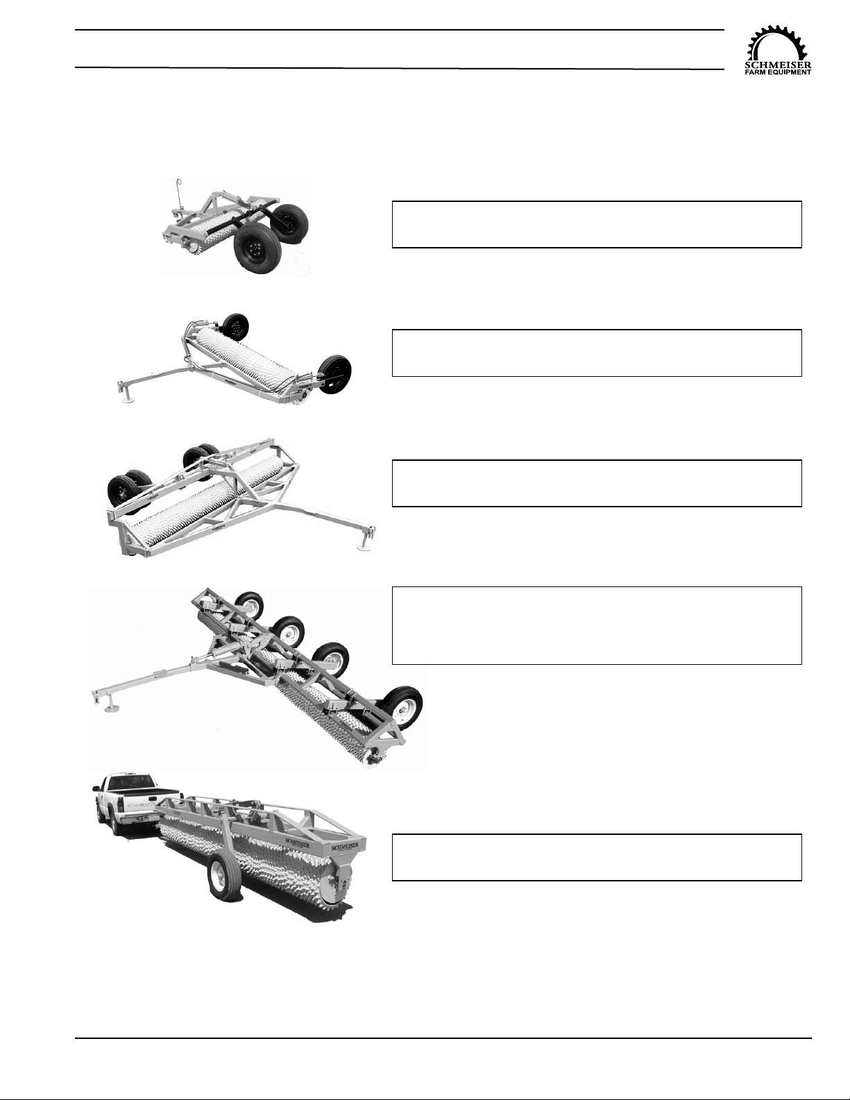
TILL AN’ PAK HYDRAULIC TRANSPORT KIT
MODELS.........................................................................5
SAFETY..........................................................................6
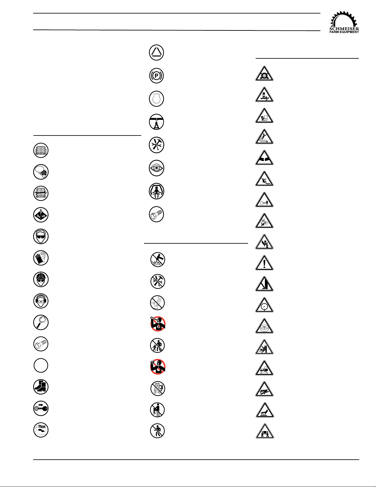
Safety Alert Symbols................................................6
Safety Icons Nomenclature.......................................7
Personal Protection/Important Information.....7
Prohibited Actions............................................7
Hazard Avoidance...........................................7
General Safety..........................................................8
Assembly Safety.......................................................8
Towing Safety...........................................................9
Safety Chain...................................................9
Highway and Transport Operation................10
Operation Safety.....................................................10
Tractor Requirements...................................10
Tractor Safety Devices..................................11
ROPS and Seat Belt.....................................11
Attaching to Tractor................................................11
Prior to Connecting Unit ...............................11
Connecting to the Tractor..............................11
Hydraulic Components Safety....................11
Maintenance Safety................................................12
Tire Safety.....................................................13
Bolt Torque Requirements............................13
Tire and Lug Torque Specifications...............13
Welding Repairs...........................................14
Storage Safety.......................................................14
Disposal of Equipment at End of Useful Life.......14
SAFETY SIGNS AND DECALS................................15
OPERATION.................................................................16
Attaching to Tractor................................................16
Initial Setup Checklist.............................................16
Implement Break-In................................................16
General operation Instructions.............................16
Detaching from Tractor............................................17
MAINTENANCE............................................................17
Lubrication Points...................................................17
Wheel Hub Bearings.....................................17
Service Items..........................................................17
Hydraulic Hoses..............................................17
Tires..............................................................17
Maintenance Schedule...........................................18
STORAGE.....................................................................19
Storage Preparation................................................19
Placing in storage...................................................19
Removing From Storage......................................19
PARTS SECTION.........................................................20
TPP3510 Hydraulic Transport Kit.........................20
TPP3510 Transport Kit Assembly..................20
TPP3510 Safety Marking and Lighting..........21
TPP3510 Transport Kit Ass’y Instructions.....22
TPP3510 Transport Kit Hub Assembly..........23
TPP3520 Hydraulic Transport Kit............................24
TPP3520 Transport Kit Assembly..................24
TPP3520 Safety Marking and Lighting..........25
TPP3520 Transport Kit Ass’y Instructions.....26
TPP3520 Transport Kit Hub Assembly...........27
TPP3530 Hydraulic Transport Kit............................28
TPP3530 Transport Kit Assembly..................28
TPP3530 Safety Marking and Lighting..........29
TPP3530 Transport Kit Ass’y Instructions.....30
TPP3530 Transport Kit Wheel Axle Bearing
Assembly........................................................31
TPP3530 Wheel Hub Bearing Assembly........32
TPP3540 Hydraulic Transport Kit............................33
TPP3540 Transport Kit Assembly..................33
TPP3540 Safety Marking and Lighting..........34
TPP3540 Transport Kit Ass’y Instructions.....35
TPP3540 Transport Kit Hub Assembly...........36
TPP3540 Hydraulic Diagrams........................37
TPP3550 Hydraulic Transport Kit -Straddle Axle.....38
TPP3550 Transport Kit Assembly..................38
TPP3550 Safety Marking and Lighting..........40
TPP3550 Transport Kit Ass’y Instructions.....41
TPP3550 Transport Kit Wheel Axle Bearing
Assembly........................................................41
TPP3550 Wheel Axle and Hub Assembly......42
LIMITED WARRANTY STATEMENT............................43