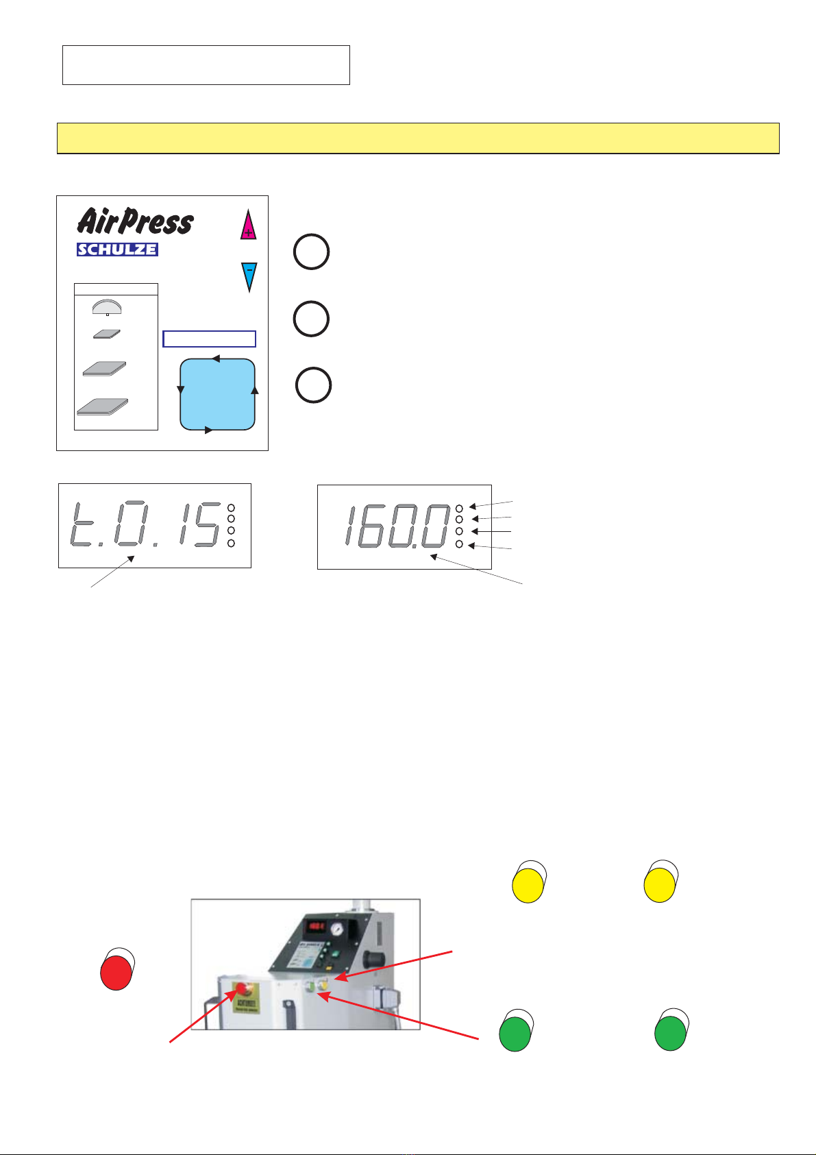
Schulze AirPress4 Quick guide

TECHNICAL DATA
dimension in ca: 160 x 160 x 200
weight inclusive cabinet 160kg
operation current 230volts
electrical performance 2,5kw
airconsumption per operation cycle 3,3L
pressure performance at 6bar 2490kg
max. pressure 6bar
temperatur range<. 0 - 220°C
adjustable operation time: 0 - 9´ 59”
max. variations of temperature at 180°C
(measured inside the heat plate) -1/+3°C
Pneumatical Press with 4 working platen
heat platen dimensions: 40 x 50cm
base platen: 4pieces 40 x 50cm
Interchangeable heat platen:
20 x 20cm
38 x 45cm
40 x 50cm
USE INSTRUCTIONS
display
pressure display
temperature and time adjustor
pressure switch OFF
pressure switch ON
Plugin for cooling pump max. 2amp
compressed air adatper
power connection cable
main switch
fuse 12amp
emergency OFF switch
working plate
(base plate)
power cord of the heat plate
fastening screw of the
heat plate
heat plate
4
cooling pump
cooling plate
1

Pressure adjustment
Application pressure will change upon turning the right button: clockwise increases the pressure, opposite turn
the pressure. For storing the adjustment just press the button. Desiring to change the pressure just
The pressure can be read on the display top right:
1,0 bar = ca. 415kg
2,0 bar = ca. 830kg
3.0 bar = ca. 1245kg
4.0 bar = ca. 1660kg
5.0 bar = ca. 2075kg
6.0 bar = ca. 2490kg
It is recommended to adjust the pressure suitable to
to be done:
Cap options: 0.2 till max. 0.6bar
Platen 20 x20 cm 0.2 till max. 1.0bar
Platen 38 x 45 cm 0.5 4.0bar
Platen 40 x 50 cm 0.5 4.5bar
decreases
pull the button.
the work
till max.
till max.
After each and every change: the press should be closed for the reason of rechecking of the newly adjusted pressure.
Damages resulting from wrong pressure adjustments are excluded from warranty claims.
Switch ON
Before the press to be switched on first time, please check the plugin's proper conditions and also the safe
connection of the neutral cable.
Connect the hose of compressed air properly. Pressure should not exceed 6bar. Upon finish of operation please
disconnect the air pressure tube.
The press has to be switched on with the green rocker switch. The current temperature of the heat platen will be shown
on the display while heat will continously be developed until the chosen temperature has been achieved. (LED1 lights)
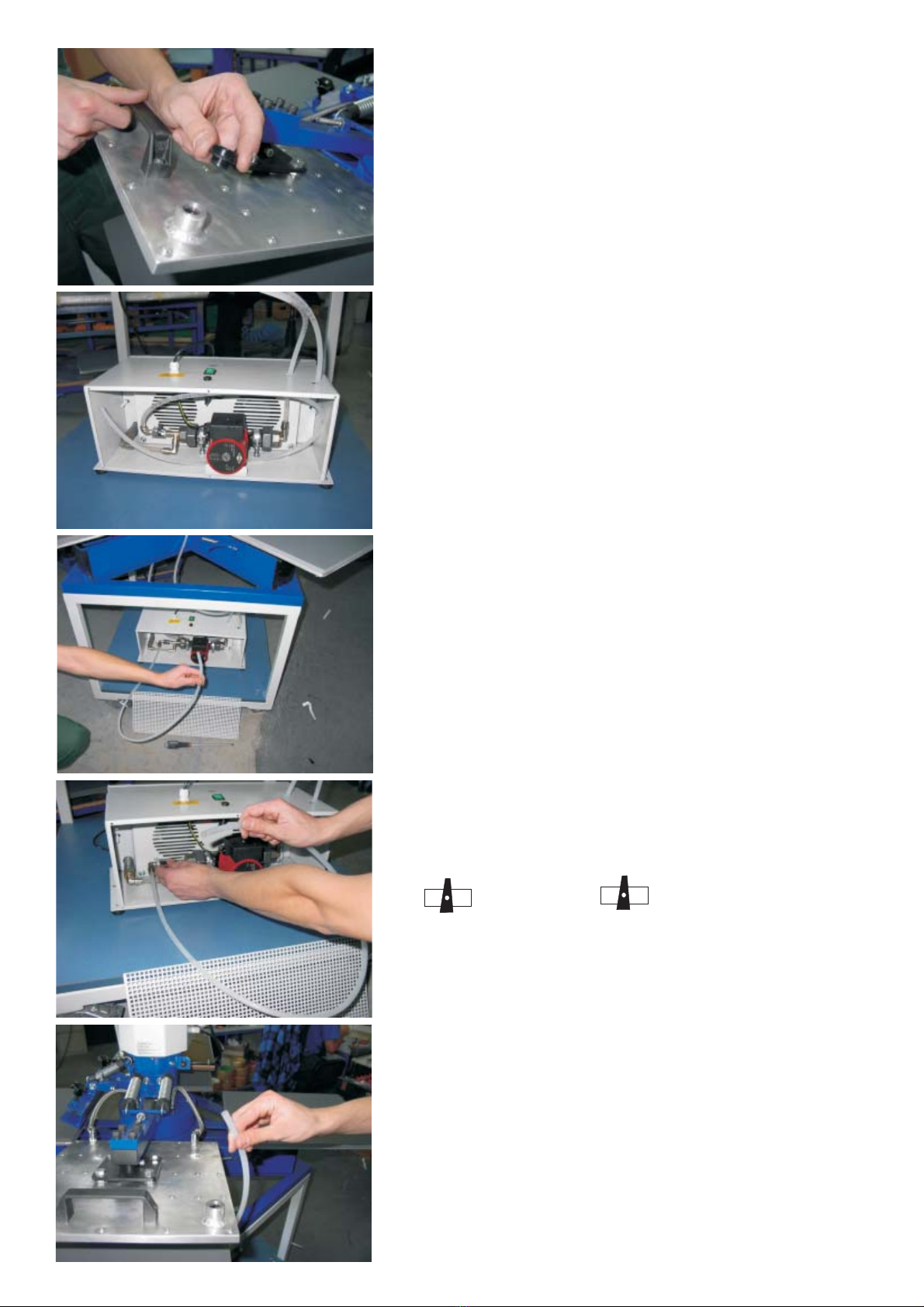
In case the press will be operated for several days uninterrupted, please drain the water out of the filter by push
the black button (left below the connection fitting) once a day.
Maintenance
Safety
For cleaning of the press we recommend a soft cloth. A mild household cleaner should maybe used in addition.
Please avoid usage of any scrubbing sponges, solvents and/or petrol.
Cleaning
Air pressure and power have to be disconnected before commencing any service work. Pull out the plug additionally.
For replacing/interchange of any platen please wait until the installed platen are cooled down entirely. Other wise
danger of serious burnings.
At the press are 2 grease nipples
The grease used should be temperature resistant up to 160C.
(left/right of the lower end of the tower) to be greased with a gease gun every 4 weeks.
Please make sure that the grease penetrates the bearings.
For optimal safety and performance please read these manual instructions thouroughly.
that operation of the press is permitted for one single person only. A sesond person should not even be around
in the action radius of the operator. please push the “emergency button” instantly. The press will then
be opened automatically, switches are blocked so that the press can not be moved downwards. For continuing work the
”emergency button” has to be pulled.
Please note
In case of an accident
Replacing silicone mat
Cap module:
Please note:
The press has to be cold for replacing the silicone mat.
Please make sure that the old mat has been removed entirely. Even small remaining spots of the old silicone mat and/or
adhesive have has to be cleaned up. Spread new temperature resistant silicone adhesive evenly with a spatula.
Then the new silicone mat has to be layed on the glued surface and right there after charge the whole mat with
a board (straightly) of + weight-load of ca. 20kg for about 24hours to set/drying-off duration.
The cold heat plate should be layed on the new silicone mat and smoothed together with a paper
tape, remaining for approx. 24 hours drying time
The silicone mat should be approximately 2cm larger (each dimension) than the base plate. To be cut to
measure by a clean sharp knife after the drying period.
2
The press should be operated by trained staff only and, of course, after acknoledging these manual intsructions.

Operation instructions
PROGRAMMING
1. Press button 1 and hold for 5sec until LED flashes.
2. Upon the flashing LED the display shows the adjusted temperature.
The programming mode has been switched on.
3. Adjust a new temperatur with the keys 2 or 3.
5. Push key 1 briefly to finish programming mode.
4. Push key 1 briefly.
The adjusted time will be shown on the display.
Re-adjust the time by pushing keys 2 or 3.
1
2
3
TEMPERATURE Press key 3 briefly: the display shows the newly adjusted temperature.
TIME Press key 2 briefly: the display shows the newly adjusted time. Max 9'59”.
LED 1 - press is being heated.
LED 2 - diode flashes = programming ON
LED 3 - temperature range (inactive)
LED 4 - temperature adjustment (inactive)
Temperature in °C
Example:
Timing 15 seconds
Minutes
ON ON
Pneumatic
OFF OFF
Operation:
Please press both green keys simultaneously until
the press has arrived at its base position. After adjusting
the time the press will open up automatically
PRESS
PRE-PRESSING
Vor opening the press before finishing the adjusted working
cycle please press both yellow OFF keys at once and keep
them down until the heatplate stopped at its top position.
Then the press could be swang away to side.
EMERGENCY SHUT OFF
Upon a dangerous situation press the red key at the frontside of the
press immediately. The press will open up automatically. For continuation
operation just pull the red key.
The press should be operated by trained staff only.
3
20 x 20 cm
38 x 45 cm
40 x 50 cm
17x7cm
0,3 bar
0,6 bar
2,0 bar
2,5 bar
max.0,6 bar
max.1,0 bar
max.4,0 bar
max.4,5 bar
1. Confirmation 5 sec.
2. Temperature +/-
3. Confirmation 1 sec.
4. Time +/-
5. Confirmation 1 sec.
6. End
Programming
Pressure
Confirmation
Time
Temperature
The press is for application of transferring and transfer foils onto textiles.
For optimal results please contact the manufacturers of the textiles.
Flex Foil: 150 – 160°C, time 12sec
FlexS Foil: 155 – 160°C, time 12sec
Flock Foil: 150 – 160°C, time 15sec
Flock Velcut 150 – 160°C, time 15sec
Example: Adjustment of the press
All data mentioned without guaranty, please do your own testings prior any series work..

SWITCH PLAN
SCHEMAT POLACZEÑ
F1
F3
S10
S10
+
-
12VDC
F2
1,5A
Netzteil/zasilacz 12VDC
+-
12VDC
Relais 50A
Przekaznik
elektroniczny
230VAC
CRYDOM 50A
Temperature sensor
KTY 84-1
Heating element/grzalka
31
Stecker/wtyczka/Plug
heat plate/plyta grzewcza
2000W
Temperatursicherung
A3K1 Z 540
1F25
FILTER
6
blue
63
2
1
4
5
czarny
schwarz 230VAC
black
czarny
schwarz 230VAC
black
czerwony/ rot/red +
Temperature sensor niebieski/ blau/blue
Temperature sensor
Stecker/Wtyczka/Plug
7
++
--
ROM-3 0 - 220°C
12VDC
K
F
S1
S
CRYDOM
Time OFF 12V+
Thermoregulator-timer
S10 Hauptschalter/ Wlacznik glówny / Main switch
S1 Time start........... (czarny / schwarz / black )
S4 Setup...................(zolty / gelb / yellow )
S5 [-]Temperature......... (zielony / grün / green)
S6 [ +] Time ..............(Brazowy / braun / brown)
Temperature sensor ( - )........(niebieski / blau / blue)
Temterature sensor (+).........(czerwony / rot / red)
F1 bezpiecznik / Sicherung / fuse 10A
F2 bezpiecznik / Sicherung / fuse 12VDC 1,5A
12V+ czerwony / rot / red
12V- niebieski/ blau / blue
3 + 6 grzalka / Heizelement / Heating element
1 + 4 czujnik / Temperatursensor / Temperature sensor
7 uziemienie / Schutzleitung / Nonfuset earth conbuctor
Power supply unit
230VAC
6A
L
N
0
230VAC
7
S6
S1
S2
S4
S5
4
Setup
auxialiary switch
4
Cooling pump
Ventilator
Pompa
Wentylatory
4

Controlling unit of the Airpress´s pneumatic
++
--
ROM-3 0 - 220°C
12V
Setup
K
F
S1
S1
S2 S2
S
CRYDOM
Time OFF 12V+
pressure switch ON
pressure switch ON
pressure switch OFF pressure switch OFF
Pneumatic ventil
pressure display
-+
pressure
cylinder
heat plate compressed air max. 6bar
Micro switch
Activates the control above the work plate only.
Moving of the
heat plate
Micro switch
5
blue/niebieski
red/czerwony
red/czerwony
red/czerwony
230VAC 12V 12V
-+
Power supply unit/Zasilacz
10
13 blue/niebieski
blue/niebieski
red/czerwony
red/czerwony
red/czerwony
red/czerwony
red/czerwony
red/czerwony
red/czerwony
6
7
44
33
12
8
11
9
2
0
14
1
10
white/bialy white/bialy
white/bialy
white/bialy
white/bialy
5
4
3
Zweihandrelais
Wlacznik Obureczny
Two Hand Relais
Electromagnet
+
+
-
On
On

1. Unscrew but air deventilation valves and swing the cooling board
slightly up.
2. Unplug the cooling pump and then unscrew the cover of the
pump.
3. Remove the connection hose carefully.
4. Open up the water valve for filling up the unit.
5.
6.
7.
8.
Fill up the cooling unit by a water hose or a
funnel until it overflows the de-ventilation valves.
Close the lower valve and drain the water hose.
Close the de-ventilation valves carfully by hand.
Lay down the connection hose into the unit's housing
and fasten the cover tightly.
Closed Open
Cooling unit to be filled with water.
6

7
TESTING REPORT
operation time at 220°C.......hours
testing with transfer foil
warnings signs
packaging
Underframe (greasing of the shafts)
Heat and base platen, Symmetry Silicone, Teflon
Electrical connections, Protection and Grid cables (cords)
Electronic, max. temperature 220°C, checking of functions
Operation duration upon 180 °C -/+ °C.......hours
Temperature tolerance upon 180°C - /+ °C
o
o
o
o
o
o
o
o
o
o
D
EG conformity declaration according EG-rules for machines 89/37 EC
Die Walter Schulze GmbH
Schmalenbachstr.15
D-12057 Berlin
Declares herewith as European authorized agent for the manufacturer firm Romanik that
the following described machine:
Transfer Press...............Series Number............
Corresponds with the following EG Guidelines:
Machine Guidelines (89/37)
Low Voltage guidelines (72/23)
EMV guidelines (89/336)
Applied Standards and Technical Specifications:
EN 292-1, EN 292-2 “Safety of Machines”
EN 60204-1 Electrical Equipment of Machines
Berlin the..........
__________________________
Peter Meidinger
Chief Executive Officer
Series number....................
CAP
PRESS4050
visato
visato
visato
4
Table of contents
Other Schulze Power Tools manuals

Schulze
Schulze DTG Press User manual

Schulze
Schulze Air press-4 X User manual

Schulze
Schulze E-Power Duo Press User manual

Schulze
Schulze Pneu Press User manual

Schulze
Schulze BluePRESSLine DTG-4-S User manual

Schulze
Schulze BluePRESSLine Mug 4 User manual

Schulze
Schulze Swing S Duo pneu User manual

Schulze
Schulze Big-O-Matic 90130 User manual

Schulze
Schulze BluePRESSLine Mug 4 plus User manual

Schulze
Schulze BluePRESSLine Size 3-S User manual