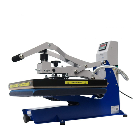
Schulze Swing S Duo pneu User manual

Instruction manual
Version 18.04
Semi-automatic heat press
Swing S Duo pneu
Version 18.04 1/14

1. Introduction
1.1 Content
1. Introduction 02
1.1 Content 02
1.2 Construction of the machine 03
1.3 Technical data 03
1.4 Replacea le heating plates 04
1.5 Replacea le ase plates 04
1.6 Safety arrangements of the heat press 04
1.7 Safety arrangements at the workplace 04
2. Initiation 05
2.1 Notes regarding transportation 05
2.2 Installation of the heat press 06
2.3 Connection of the press to the compressed air 06
2.4 Power supply 06
2.5 Initiation of the heat press 06
3. Working with the heat press 07
3.1 Programming of the electronic devices 07
3.2 Application range and sample adjustments of the heat press 09
3.3 Position adjustment of the heating plate 09
3.4 Pressure adjustment 09
3.5 Instruction for replacement of the heating plate 10
3.6 Instruction for replacement of the ase plate 10
3.7 Safety frame 10
. Maintenance 11
4.1 Daily Maintenance 11
4.2 Instruction for the activation of the main fuse 11
4.3 Instruction for the replacement of the silicone mat 12
4.4 Instruction for the replacement of the thermal fuse 12
4.5 Instruction for the replacement of the thermo couple 12
4.6 Wiring diagram 13
4.7 Warranty terms and conditions 14
4.8 Testing report 14
4.9 EC Conformance - Declaration 14
Version 18.04 2/14

1.2 Construction of the machine
1. Stand
2. Base plate
3. Main switch
4. Pressure adjustment
5. Pressure gauge
6. Touch display
7. START switch / Movement to the left
8. Emergency utton
9. Heating plate with safety frame
10. START switch / Movement to the right
11. Compressed air connection
12. Spiral tu e with heating plate plug
13. Foot-operated switch
1.3 Technical data
Technical data Swing S Duo pneu
Dimensions of the press 90 x 105 x 160 cm
Dimensions of the press for the transport 80 x 120 x 180 cm
Weight of the press with stand 129 kg
Weight of the press for the transport (without stand) 118 kg
Power supply 230 VAC
Rated power ( with plate 38 x 45 cm) 2 kW
Rated power ( with plate 40 x 50 cm) 2,4 kW
Temperature range 0 – 220° C
Time settings 1 sec. - 99 min. 59 sec.
Pressure force y 6 ar ca. 1200 kg
Max. pressure 6 ar
Air consumption during one cycle 1,2 l
Main fuse B 16A
Noise The machine generates noise less than 70 dB (A)
Version 18.04 3/14

1. Replaceable heating plates
For the press there are several heating plates availa le. The
instruction for the replacement can e found in chapter 3.5
1. Heating plate with safety frame 40 x 50 cm
2. Heating plate with safety frame 38 x 45 cm
1.5 Replaceable base plates
For the press there are several ase plates availa le. The
instruction for the replacement can e found in chapter 3.6.
1. Base plate 40 x 50 cm
2. Base plate 38 x 45 cm
3. Trapezoid plate 20 x 43 x 38 cm
4. Base plate 28 x 38 cm
5. Base plate 20 x 20 cm
6. Base plate 12 x 12 cm
7. Base plate 10 x 45 cm
1.6 Safety arrangements of the heat press
The Swing S Duo pneu heat press is equipped with different safety arrangements, to make a safe usage possi le.
Main fuse B16A
The main fuse is situated in the ack part of the press. In case of overcharge, the main fuse prevents the heat press from getting
damaged. Once the fuse was switched off, it has to e activated. The instruction for activation of the main fuse can e found in
chapter 4.2.
Thermal fuse
The thermal fuse is situated directly on the heating plate and it stops the power supply if the temperature exceeds ~260°C. If the
fuse is activated, the temperature sinks down to 90°C. After that the power supply gets activated again and the temperature of t he
heating plate rises and it’s possi le to continue the work with the press. Over time the thermal fuse may wear out and cut off the
power supply y lower temperature, for example y 180°C. In such case it’s needed to replace the thermal fuse as soon as
possi le. The instruction for the replacement of the thermal fuse can e found in chapter 4.4.
Safety valve 6 bar
The safety valve 6 ar is located at the pressure pipe in the press. If the pressure exceeds 6.0 ar, the valve will e activated
automatically.
Emergency button
Has een installed to eliminate the residual risks. In dangerous situations push the red emergency utton. It is situated in front of
the press. The press will open automatically. To resume the work pull the utton ack again.
Automatic switch-off
If the press doesn’t get opened within 15 seconds after the pressing process, the heating element switches off automatically, to
avoid fire danger.
Safety frame
The safety frame is located at the heating plate. If it will e activated, the press will open and the pressing process will e
suspended.
1.7 Safety arrangements at the workplace
Set-up and installation of the heat press
The set up and installation of the press has to e done under supervision of an authorized person y the company owner.
Depending on the model and weight of the heat press, the installation has to e done y 2 or more persons. The press should e
situated on the flat, non-inflamma le surface, in a room with constant temperature and constant moisture. Keep the machine away
from dusty rooms, ecause dust could have a negative influence on some parts of the machine. Very important! The machine may
e connected only to an installation provided with a protection against electric shock. The machine is destined for industrial use
only.
Testing the machine
After the correct installation of the machine it is important to ensure that the machine works properly, is not damaged after the
transportation and has no safety defects. The testing can only e done y the employer or other authorized persons. It is
mandatory to guarantee a correct installation and safe usage of the machine. After receiving the machine, check the packaging.
The testing should e protocoled. If any irregularities regarding functionality or safety are found during the testing, these have to e
noted and reported to Walter Schulze Gm H in written form within 7 days. Until the clarification the machine can not e used.
Version 18.04 4/14

Information and education
According to §81 the industrial law and § 14 employment protection law (german law), the advice from the producer and general
safety arrangements at the workplace, the employer has to make arrangements to give all information a out the safety, function
and the range of application to the user. In particular the user needs to e acquainted with the complete manual and e explicitly
informed of the dangers of working with the machine. The details have to e explained in a coherent form and language. Every
user is o ligated to a safe usage of the machine and to read the manual instruction efore start working with the machine. Using
the machine means, that the operator has read the instruction and is aware of the possi le risks of working with the machine.
Safety arrangements
In order to ensure optimized safety, please read the instruction manual precisely. Only one person is allowed to work on the
machine at the time. The machine has to e under supervision the whole time, when it is working. Supervise the machine till it is
switched off and the power plug is pulled out. Pressure adjustment has to e done when the press is open. There should e no
unauthorized persons near the machine while it’s working. Beware of the heating plate - risk of urns. Attention! The press opens
automatically - keep the safety clearance. In case of emergency, please push the emergency stop switch, which is situated in the
front of the press. The machine will stop immediately. The power plug has to e pulled out of the power supply, while maintenance.
Using the press with certain materials may create a strong smell. That’s why the user should evaluate the need for a ventilation
system at the workplace. The type of ventilation should e used as needed and depends on the size of the room and used inks.
The machine has to e installed at a place with enough space around the machine. The space in front of the machine has to e
wide enough. Nothing can distur the operator at work. Do not install the machine in doors, floors or usy places. All wires should
e placed in a safe way, to make sure they will not pose a threat for the person working at the machine or passing it. In case of
damages or untypical signals from the machine, please disconnect the machine from the power supply, contact the service and do
not work with the machine, till the pro lem is solved. All repairs should e performed after consulting the service. Do not remove
machine covers while the machine is working.
Starting the working procedure
The operator needs enough space and free distance to all switches and uttons to work with the machine. Safe position allows
operator to switch on the emergency utton in every moment.
Other risks and dangers
There are some mova le elements on the machine, which can cause injuries of hands or fingers. For reasons of worka ility, these
elements cannot e eliminated. It is important to work with the machine with great care and e alert to avoid other dangerous
situations. The machine should e operated in accordance with the manufacturer’s recommendations to avoid risks. The machine
complies with the essential requirements laid down in regulation for machines. A ove information has een worked out in
accordance with the standards PN-EN 12100:2012. The machine is constantly upgraded in order to improve its safety. All
comments regarding the contents of this manual can e addressed to the distri utor or manufacturer.
2. Initiation
2.1 Notes regarding transportation
The Swing S Duo Pneu press is fixed into the pallet for transport. It is covered with protective foil. It should e checked, if the
packaging and the machine are in good condition without damages. It has to e done just after receiving the goods from the
transportation company and in accompany of a responsi le person. Later on, if you have to send the machine somewhere else,
place it in the stand in the same way as you received. For the transport the machine has to e cold and the upper part of the press
has to e locked, to prevent its movement.
Version 18.04 5/14

2.2 Installation of the heat press
Prasa znajduje się na metalowej podstawie z uchwytami ułatwiającymi przenoszenie prasy. Prasę należy przenosić w 4 oso y.
Urządzenie należy przenosić ostrożnie, zwracając uwagę na utrzymanie równowagi. Prasę należy postawić na specjanym
metalowym stoliku, który należy złożyć zgodnie z dołączoną do niego instrukcją.
2.3 Connection of the heat press to the compressed air
The Swing S Duo Pneu is a pneumatic press, which has to e connected to compressed air. The maximum pressure inside the
press cannot exceed 6 ar. The air has to e dry and clear of oil. If required you may use additional filter and driers. The port for
the compressed air at the press is equipped with air compressor connector DN 7,2 (picture 1). After finishing work, the
compressed air has to e disconnected and the container of the filter emptied. The instruction can e found in the chapter 4.1.
There can e water in the container from the compressed air. If the compressed air system has no additional dessicator, the
container needs to e checked every 4 hours during operation sequence. It can e emptied y unscrewing the valve while the
compressed air is connected (picture 2). If in the container esides water there is also oil, the air compressor is not working
properly. In this case the press has to e switched off and the compressor has to e repaired. The oil from the compressor can
damage the pneumatic valves in the machine. If needed contact the service for help.
2. Power supply
The Swing S Duo Pneu press has to e connected to a voltage of 230 VAC / 50 Hz. The Press is equipped with a power plug. Make
sure that the power outlet is in the right condition and that the grounding is connected to the power outlet. Caution: Please do not
connect this press to any other outlet (socket) than those equipped with ground-fault protection ELCB (earth leakage circuit
reaker). In case of dou t ask your licensed electrician to check the wiring. Connecting the machine to a socket that is not earthed,
or where the earthing does not work properly, is hazardous to health and dangerous for the machine. Any damages arising from an
improper plugging invalidates the warranty.
2.5 Initiation of the heat press
Swing S Duo Pneu is a pneumatic press. Before starting the work with the
machine the heat and ase plates have to e installed. Instructions for installation
of the plates can e found in chapters 3.5 and 3.6. The foot operated switch has to
e connected to the press (picture). Before connecting the machine to the
electricity check if the plug is not damaged and if the socket is earthed properly.
After connecting the machine to the electricity and to the compressed air, the
machine is ready for work.
The press has to e open while eing turned on. It has to e also open while
heating up. In order to switch the press on, press the green switch located on the
left side of the press. The green switch is on and the press heats up to the
programmed temperature. The press can e operated in automatic or manual
mode. Select the mode. If the work is finished, the switch has to e switched off
and the plug has to e pulled out.
Version 18.04 6/14

3. Working with the heat press
3.1 Programming of the electronic devices
After switching on the press, the startup screen is showed on the display
(picture 1). After that the information a out movement of the press to the start
position will show on the display (picture 2). Touch the screen to set the right
position of the heating plate.
Press any of the indicated fields to change the press parameters (picture 3).
The program num er, which parameters will e changed, is highlighted on the
screen. Use the arrows to select other program (picture ).
In order to change the individual parameters in active program, use uttons
„-” and „+”(picture 5) and push the green utton to save the changes.
In order to change the name of the active program, push the field with the
name (picture 6).
Version 18.04 7/14

Then, type the new name using the key oard showed on the screen. (picture
7). Push the green utton to save the changes.
Swing S duo pneu press is equipped with counter (picture 8).
Use the uttons „-” and „+” to change its inputs.
Push the indicated utton to reset the counter (picture 10) and save the
changes y pushing the green utton.
Push the indicated utton to select the mode: automatic, prepressing and
postpressing (picture 11).
Then switch the selected mode on or off (picture 12). After confirming with the
green utton, the changes will e saved (for the active program). In order to
change the language of the menu, push the right utton (picture 12). After
pushing the green utton, the language changes will e saved (for whole menu,
for every program).
Version 18.04 8/14

In the manual mode:
After pushing the press icon on the screen (picture 13), the foot-operated
switch, or the green START switch, situated on the same side of the
machine as the heating plate, the heat plate will go down. In order to
change position of the heating plate, push the green START switch,
situated on the opposite side of the heating plate position.
Example 1:
The heating plate is situated above the left base plate.
After pushing the press icon on the screen (picture 13), foot-operated
switch or green START switch, situated on the left side of the machine,
the press will close on the left base plate.
Example 2:
The heating plate is situated above the left base plate. After pushing the green START switch, situated on the right side of the
machine, the heating plate will move to the right. After renewed pushing of the same START switch, the press will close on
the right base plate.
In order to reak the pressing process efore the programmed time is up, use the foot-operated switch or one of the green START
uttons situated on the machine.
In the automatic mode, without prepressing and postpressing:
After pushing the press icon on the screen (picture 13), foot-operated switch or one of the START uttons:
1. The heating plate will move to the new position
2. The heating plate will go down and the pressing process will start
3. The heating plate will go up and stop.
In the automatic mode, with prepressing and postpressing:
After pushing the press icon on the screen (picture 13), foot-operated switch or one of the START uttons:
1. The heating plate will move to the new position
2. The heating plate will go down, prepressing process will start
3. The heating plate will go up, and move to the start position
4. Renewed pushing of the START switch
5. The heating plate will move to the new position, pressing process will start
6. The heating plate will go up and move to the start position
7. Renewed pushing of the START switch
8. The heating plate will move to the new posistion, pospressing process will start
9. The heating plate will go up and stop.
3.2 Application range and sample adjustments of the heat press
The heat press is designed for pressing transfer foils on textiles. To get good achievements get in contact with the producer of the
textiles. Here are example settings:
Film FlexS 155°C – 160°C time 15 seconds
Film A-Flex 155°C – 160°C time 15 seconds
Film Flock 160°C – 180°C time 15 seconds
Su limation 190°C – 205°C time 50 seconds
Before each work sequence it is needed to do tests for pressing transfers and to check the resistance on washing. Use cotton
textiles, polyester or mixed textiles according to the specifiaction of the foil.
3.3 Position adjustment of the heating plate
If the heating plate moves too far or not enough to the new position, the settings of the positions have to e adjusted. Press the
settings utton (picture 1). Then enter the settings (picture 2). Change the chosen parameters using uttons „+” and „-”. Then save
the changes y pushing the green utton (picture 3). After every change the test has to e performed.
3. Pressure adjustment
On the Swing S Pneu press, the pressure setting can e adjusted precisely. The pressure force can e adjusted with the kno
situated on the left side of the machine. The pressure force has to e adjusted to the size of the ase plate. After every new
adjustment, close the heat press to check the new settings. If the heat press gets damaged because of too big pressure, the
terms and conditions of warranty are not more valid. The manufacturer does not response for damages caused by wrong
adjustment of the pressure force.
The pressure force can e checked on the manometer which is situated in the upper part of the machine.
Version 18.04 9/14

To adjust the pressure do the following:
1. Take the pressure reading (picture 2)
2. Unlock the kno , y pulling it (picture 1)
•Rotate the kno to the right to increase the pressure (picture 1)
•Rotate the kno to the left to decrease the pressure (picture 1)
3. To lock the setting, push the kno to the press again.
4. Test the pressure y closing the press.
If the pressure will exceed 6 ar, a safety valve will e activated. In this case the pressure has to e reduced.
3.5 Instruction for the replacement of the heating plate
In order to replace the heating plate, turn off the heat press, disconnect it from the electricity and wait till it gets cold.
Then disconnect the heating plate from the press (picture 1). Loosen the fixation screw with the allen key (picture 2). Hold the
heating plate, unscrew it completely and place it carefully on the ase plate (picture 3). Take the heating plate carefully and put it
on a soft underground, ecause the Teflon cover should not e damaged. Then take the new heating plate and tighten it with the
allen key. Connect the heating plate to the press. The heating plate can not e rotated.
3.6 Instruction for the replacement of the base plate
In order to replace the ase plate, loosen the fixation screws (picture 1). Then replace the ase plate (picture 2). Tighten the fixation
screws (picture 1).
3.7 Safety frame
In order to ensure optimal safety, the Swing S Duo Pneu has
een equipped with a safety frame (picture). It prevents the
operators hands from eing urned or damaged y the heating
plate. The safety frame is connected to the heating plate. When
the machine is working, and the safety frame will e activated,
the heating plate will move up automatically (picture) and the
signal will sound. To continue the work with the machine, the
press has to e activated.
Version 18.04 10/14

. Maintenance
.1 Daily maintenance
The surface of the heating plate and ase plate needs to e clean all the time. The heat plate has to e cleaned with a clean and
dry cloth. Avoid contact with the heating plate – risk of urns. Clean the silicon foam with a soft cloth. Use mild household cleaners.
It is not allowed to use solvents or naphtha.
At least twice a day the compressed air filter has to e controlled. It is situated on the right side of the machine. If needed, remove
its content. It can e done y pulling and rotating the kno situated under the container (picture 1). If in the container the water still
remains, disconnect the machine from the compressed air and remove the container (pictures 2-3). Then pour off the water from it.
If needed, the filter which is situated inside of the container can e cleaned. After removing the container (pictures 2-3), loosen the
fixation screw (picture ). Take the filter out, clean it and reassem le ack again (picture 5).
If there is oil in the container (compressor damage), switch off the press immediately and repair the compressor. Oil in the system
may damage the press.
.2 Instruction for the activation of the main fuse
If the heat press does not work after switching it on, check the main fuse in the press. The main fuse B16A is situated in the ack
part of the press. Before activating the main fuse, turn off the heat press and remove the power plug from the socket. Then
remove the ack cover (picture 1) and activate the main fuse y pushing its lever up (picture 2).
Version 18.04 11/14

.3 Instruction for the replacement of the silicone mat
To replace the silicone mat, the press has to be cold and disconnected from the electricity. For the replacement you will need a
new silicone mat, silicone glue, acetone and a notched trowel.
1. Remove the old silicone mat completely, using the knife.
2. Clean the plate from the old silicone glue (you can use the sandpaper).
3. Clean the surface of the plate and silicone mat (the side which will e glued) with the acetone.
4. Put the new silicone glue on the surface of the plate and use the notched trowel to spread it. Use a neutral, colorless, heat
resistant silicone glue
5. Put the new silicone mat on an even, flat surface (make sure that the side which will e glued is facing up). Then put the ase
plate on the mat and press it strongly (we recommend to use the ar clamps)
6. Then apply an additional portion of siicone glue along the edge of the ase plate
7. Let the glue dry for 24 hours
8. Take off the ase plate and cut off the protruding edges of the silicone mat.
. Instruction for the replacement of the thermal fuse
The replacement of the thermal fuse has to e
done y an authorized person and after consulting
and confirming the failure with the supplier. First
turn off the heat press, remove the plug from
the socket and wait, till the heat press gets
cold. Unscrew the cover and take out the
insulation (pictures 1 – 2). Unscrew the thermal
fuses (pictures 3– ) and assem le new ones. Fix
the thermal fuses to the heating plate. Put the
insulation and set the cover ack on the heating
plate. By heating plates size 40 x 50 cm oth
thermal fuses have to e replaced.
.5 Instruction for the replacement of the thermo couple
The replacement of the thermo couple has to e done y an authorized person and after consulting and confirming the failure
with the supplier. First turn off the heat press, remove the plug from the socket and wait, till the heat press gets cold. The
thermo couple is situated directly on the heating plate. It sends readings from the heating plate temperature to the electronics.
Unscrew the cover and take out the insulation carefully (pictures 1-2). Unscrew and take out the thermo couple (pictures 3- ).
Cut off 2 cm of the wires (picture 5). Remove the ca le isolation (pictures 6-7). Connect the ca les to the ceramic terminal
locks and fasten them tight (pictures 8-9). Lay the wires carefully under the heating plate cover. They should e situated
etween the insulation and the cover. Set the cover ack on the heating plate.
Version 18.04 12/14

.6 Wiring diagram
Version 18.04 13/14

.7 Warranty terms and conditions
Schulze heat presses and machines used for screen printing have a warranty for 24 months. This warranty includes the whole
construction of the machine, mechanical elements, electronic device and covers. Expanda le parts, fuses and safety covers are
not included in the warranty terms. Thermo fuses, temperature sensor, switches and uttons and all springs in the machines have
a warranty for 6 months. Heat elements for BluePRESSLine Mug and Mug 4 presses have a warranty for 6 months or 500
pressing procedures.
.8 Testing report
Final check of the heat press:
o – ase, paint
o - greasing
o – Heating plate, ase plate, silicone, teflon
o – electric connection (safety wire, power ca le)
o - Elektronic, max. temperature 220°
o - Elektronic, checking of all functions
o – Working time y 180° C . . . . . . . hours
o – Temperature tolerancje at 180°C . . . . . . -/ . . . . . +°C
o – Working time y 220°C . . . . . . . .hours
o – Pressing test
o – Caution la els
Serial num er. . . . . . . . . . . . . . . . . . Date . . . . . . . . . . . . . . . . . . . . Signature . . . . . . . . . . . . . . . . . . . . . . . . . . .
.9 EC- Conformance – Declaration
The Walter Schulze Gm H
Ha erstraße 15-19
12057 Berlin
Germany
as european representative of the manufacturer company ROMANIK here y declares that the following machine:
Type . . . . . . . . . . . . . . . . . . . . . . . . . . . .
Name . . . . . . . . . . . . . . . . . . . . . . . . . . . . . . .
Serial num er . . . . . . . . . . . . . . . . . . . . . .
is compliant with the specifications of the followings EC directives:
Machinery (2006/42/EC)
Low voltage (2014/35/EU)
EMC (2014/30/EU)
used norms and technical specifications:
PN-EN ISO 12100 : 2012
PN-EN 60204-1 : 2010
PN-EN-61000-6-1:2008
PN-EN-61000-6-3:2008/A1:2012
PN-EN-60335-1:2012
Applied quality system: testing report/2016
Noise: The machinery generates noise lesss than 70 dB A
Berlin, …………………………..
Peter Meidinger
President
ALL SCHULZE machines are exempt from the waste disposal law under reg. no. DE23103005
Authorized person to make technical changes: Romanik Andrzej Romanik ul. Przemysłowa 10 84-240 Reda Polska.The manufacturer reserves the right to
make construcional and technological changes. The company is not responsi le for printing and content mistakes.
Manufacturer: ROMANIK, ul. Przemysłowa 10, 84-240 Reda, www.romanik.pl
Distri utor: Walter Schulze Gm H, Ha erstraße 15-19, 12057 Berlin, www.schulze.com
Version 18.04 14/14
Table of contents
Other Schulze Power Tools manuals

Schulze
Schulze E-Power Duo Press User manual

Schulze
Schulze BluePRESSLine Size 3-S User manual

Schulze
Schulze Air press-4 X User manual

Schulze
Schulze BluePRESSLine DTG-4-S User manual

Schulze
Schulze Cap Press User manual

Schulze
Schulze BluePRESSLine Mug 4 User manual

Schulze
Schulze Pneu Press User manual

Schulze
Schulze AirPress4 Quick guide

Schulze
Schulze BluePRESSLine Mug 4 plus User manual

Schulze
Schulze Big-O-Matic 90130 User manual