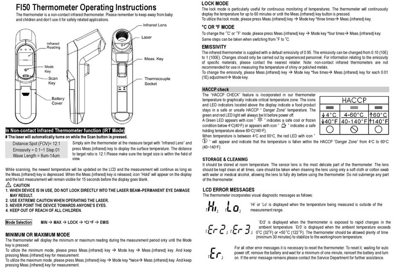
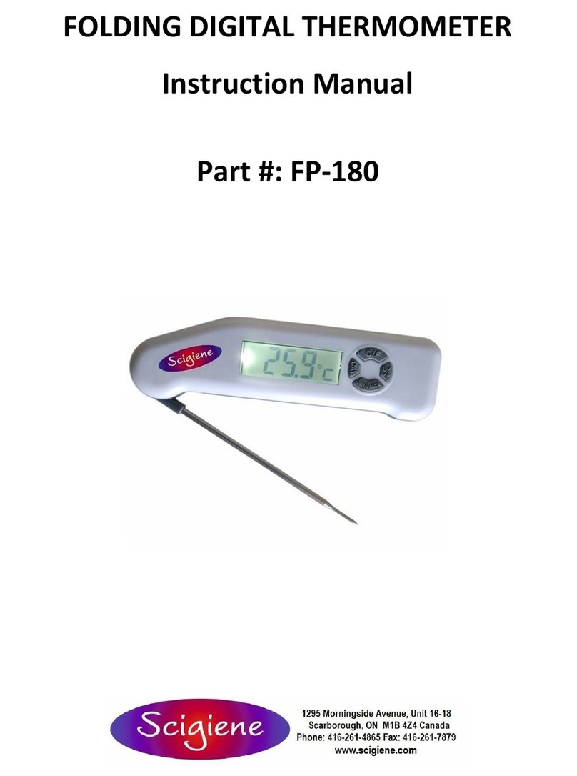
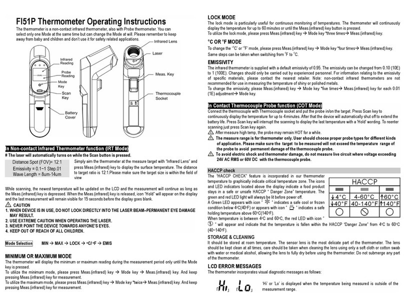
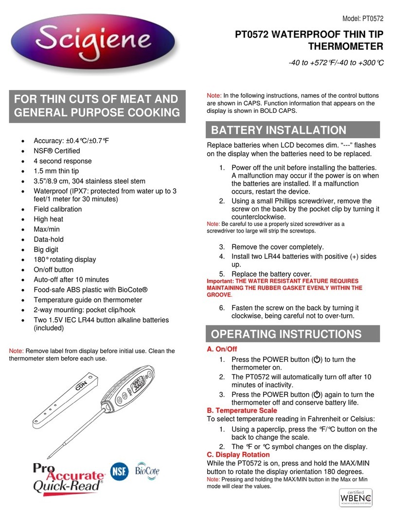
scigiene RHT-Air User manual

RHT-A
i
r
WIRELESS DEVICE FOR TE
M
PERATURE
,
RELATIVE HU
M
IDITY AND DEW POINT
IN
ST
RUC
T
ION
S
MANUA
L V
1.0x
D
1/10

1
IN
T
RODUC
T
ION
2
SPE
CI
F
ICA
T
ION
S
RHT
-
Ai
r
comes
with
a
high
accu
r
acy
and
stability
senso
r
to
measu
r
e
tempe
r
atu
r
e,
r
elative
humidity,
and
dew
point.
Because
it
ope
r
ates
with
a
mic
r
op
r
ocesso
r
,
it
can
be
fully
configu
r
ed
th
r
ough
its
USB
and
IEEE
802.15.4
inte
r
faces,
using
Modbus
RTU
commands.
The
softwa
r
e
DigiCon
f
ig
enables
fo
r
all
the
device’s
r
esou
r
ces
to
be
configu
r
ed.
RHT
-
Ai
r
can
be
configu
r
ed
to
display
the
tempe
r
atu
r
e,
the
r
elative
humidity
and
the
dew
point
and
can
display
up
to
two
of
them
simultaneously.
RHT
-
Ai
r
must
be
connected
to
an
Ai
r
Ga
t
e
-
Modbus
so
that
it
can
access
its
pa
r
amete
r
s
when
in
ope
r
ation.
The
Ai
r
Ga
t
e
Modbus
will
p
r
ovide
Modbus
RTU
access
to
its
r
egiste
r
s
ove
r
the
IEEE
802.15.4
wi
r
eless
netwo
r
k.
In
addition
to
batte
r
y
ope
r
ation
with
typical
r
ang
of
one
yea
r (
fo
r
an
update
inte
r
val
highe
r
than
60
seconds
and
stable
connection
in
an
IEEE
802.15.4
netwo
r
k
)
,
the
RHT
-
Ai
r
can
also
be
powe
r
ed
by
an
exte
r
nal
sou
r
ce.
1.1 IDENTIFICATION
The
following
elements
appea
r
in
the
f
r
ont
pa
r
t
of
the
device:
Fig. 1 –RHT-Air main screen
Communica
t
ion
Indica
t
o
r (
COM
)
:
It
signals
that
the
device
is
r
eceiving
data
f
r
om
the
Modbus
netwo
r
k.
Bu
tt
on
(
P
r
og
r
amming
)
:
This
button
is
used
to
configu
r
e
the
Modbus
add
r
ess,
the
Update
Inte
r
val
and
to
sc
r
een
changes.
Tempe
r
a
t
u
r
e
:
Envi
r
onment
tempe
r
atu
r
e
measu
r
ed
by
the
device.
Rela
t
ive
Humidi
t
y
:
Relative
humidity
measu
r
ed
by
the
device.
Dev
i
ce
’
s operat
i
ng
te
m
perature
Sensor
’
s
m
easure
m
ent range
M
easure
m
ent
Reso
l
ut
i
on
M
easure
m
ents
Accuracy
Response t
im
e
(Sensor)
I
nterva
l
between
updates
Power supp
l
y
Est
im
ated battery
li
fe
Connect
i
ons
Co
mm
un
i
cat
i
on
-10 °C
t
o 70 °C (14 °F
t
o 158 °F)
Te
m
pera
t
ure
:
-40 °C
t
o 100 °C (-40 °F
t
o 2
12
°F)
Re
l
a
ti
ve Hu
mi
d
it
y (RH)
:
0
.
0
t
o 100
.
0 % RH
(No condensa
ti
on)
Dew Po
i
n
t:
-40 °C and 100 °C (-40 °F
t
o 21
2
°F)
Te
m
pera
t
ure
:
0
.
1 °C
14 b
it
s (16383
l
eve
l
s)
Re
l
a
ti
ve Hu
mi
d
it
y (RH)
:
0
.
1
%
12 b
it
s (4095
l
eve
l
s)
See F
i
g
.
3
.
Note
:
It
i
s poss
i
b
l
e
t
o per
f
or
m
an OFFSET adjust
men
t
us
i
ng
t
he D
i
g
i
Conf
i
g so
ft
ware
t
o reduc
e
t
he
m
easure
m
en
t
error
f
ound
.
Te
m
pera
t
ure
:
Up
t
o 30 s w
it
h a
i
r
m
ove
men
t
a
t
1
m/
s
.
Hu
mi
d
it
y
:
Up
t
o 8 s w
it
h a
i
r
m
ove
m
en
t
a
t
1
m
/s (
20
t
o 80
%
RH)
.
Con
fi
gurab
l
e be
t
ween 15 seconds and 10
minu
t
e
s
(600 s)
.
Power supp
l
y
:
12 Vcc
t
o 30 Vcc
.
Consu
m
p
ti
on
<
100
m
A
.
I
n
t
erna
l
ba
tt
ery (
i
nc
l
uded)
:
L
it
h
i
u
m
3
.
6 Vcc
1
/
2
AA
0
,
80 Ah
.
O
m
n
i
Ce
l
m
anu
f
ac
t
urer
,
ER14
250
HD
m
ode
l
or EE
M
B
m
anu
f
ac
t
urer
,
ER14250
M
m
odel
.
Typ
i
ca
l
1 year - Upda
t
e
i
n
t
erva
l
grea
t
er t
han
60
seconds
.
•
I
n
t
erna
l
USB Dev
i
ce (
mi
cro-B)
f
or con
fi
g
u
r
a
t
ion
and
fi
r
m
ware upda
t
e
.
•
RP-S
M
A
f
e
m
a
l
e connec
t
or
f
or a
n
t
enna
(
i
nc
l
uded)
.
•
M
12 connec
t
or
f
or ex
t
erna
l
power (c
able
i
nc
l
uded)
.
M
odbus RTU abou
t
W
i
re
l
ess
I
EEE
802
.
15
.
4
pro
t
oco
l
(A
i
rGate-
M
odbus necessary)
.
Fig. 2 –RHT-Air's second screen
Communica
t
ion
Add
r
ess
:
P
r
og
r
ammed
value
to
identify
the
Modbus
netwo
r
k
device.
P
r
og
r
ammable
between
1
and
246
.
•
•
•
•
W
i
re
l
ess
•
•
•
•
M
ax
im
u
m
t
rans
mi
ss
i
on power o
f
25
,
11 mW (
14
dB
m
)
.
M
ax
im
u
m
Range
:
500
m
e
t
ers
li
ne-o
f
-
sigh
t
in
open
fi
e
l
d
.
Da
t
a ra
t
e
:
RF 250 Kbps
.
Recep
t
or sens
i
b
ilit
y - 92 dB
m.
Opera
ti
on band
:
I
S
M
2
.
4 GHz
.
DSSS Techno
l
ogy (D
i
rec
t
Sequence S
p
r
ead
Spec
t
ru
m
)
.
OQPSK
M
odu
l
a
ti
on (O
ff
se
t
Quadra
t
ure P
ha
s
e
Sh
ift
Key
i
ng)
.
15 opera
ti
on channe
l
s
.
•
AES-CBC-128 (Advanced En
c
ry
p
t
ion
S
t
andard)
.
Hous
i
ng
Protect
i
on
I
ndex
D
im
ens
i
ons
We
i
ght
Conf
i
gurat
i
on
software
Cert
i
f
i
cat
i
ons
E
l
ectro
m
agnet
i
c
co
m
pat
i
b
ili
ty
Po
l
ycarbona
t
e
.
I
P40
60 x 70 x 35
mm.
An
t
enna
m
easure
m
en
t:
105
mm.
Sensor
m
easure
m
en
t:
37
,
2
mm.
171 gra
m
s
/
40 gra
m
s (cab
l
e)
.
D
i
g
i
Conf
i
g – Con
fi
gura
ti
on so
ft
ware
f
or W
i
n
do
ws®.
CE
,
FCC
,
ANATEL (00172-13-07089)
;
Con
t
a
i
ns FCC
I
D
:
2AXVWBA
I
RR-NOVUSA
I
R.
E
M
C
:
EN61326-1
:
2006 C
I
SPR11
/
EN
55011
,
EN61000-4-2
,
EN61000-4-3
,
EN610
00
-
4
-
4
,
EN61000-4-6
,
EN61000-4-8
2/10

2.1 ACCURACY
O
F MEASUREMENTS AND OPERATIONAL LIMITS OF SENSORS
Fig. 3 - Accuracy of the humidity and temperature measurement
3
M
E
CHANICA
L
IN
ST
A
LL
A
T
ION
4
CON
F
IGURA
T
ION
RHT
-
Ai
r
was
designed
to
be
attached
to
walls.
By
r
emoving
the
device’s
cove
r
,
use
r
s
will
have
access
to
two
molding
holes
of
the
base,
as
shown
in
Fig.
4
.
The
device
should
be
a
tt
ached
wi
t
h
t
he
senso
r
capsule
f
acing
downwa
r
ds
t
o
ensu
r
e
accu
r
acy
and
t
he
speci
f
ied
level
o
r
p
r
o
t
ec
t
ion.
4.1 CONFIGURATION VIA USB INTERFACE
Initially,
the
fi
r
st
configu
r
ation
must
be
done
th
r
ough
USB
inte
r
face.
•
Remove
the
fou
r
set
sc
r
ews
of
the
f
r
ont
panel
of
the
RHT
-
Ai
r
device,
taking
the
necessa
r
y
p
r
ecaution
not
to
apply
fo
r
ce
on
the
inte
r
nal
connecto
r
of
the
elect
r
onic
ci
r
cuit.
Fig. 6 - RHT-Air screws
•
In
o
r
de
r
to
configu
r
e
the
USB
inte
r
face,
connect
the
cable
as
shown
in
the
following
figu
r
e.
The
exte
r
nal
powe
r
cable
is
not
used
du
r
ing
the
configu
r
ation
because
the
device
will
be
powe
r
ed
by
the
USB
inte
r
face.
Fig. 4 - RHT-Air mounting holes and measures
Fig. 5 - RHT-Air measurements
Fig. 7 – USB connector
3/10

5
ELE
C
T
RICA
L
IN
ST
A
LL
A
T
ION
5.1 EXTERNAL P
O
WER SUPPLY CONNECTION
•
Afte
r r
emoving
the
f
r
ont
panel,
r
emove
the
insulation
film
f
r
om
the
batte
r
y.
Fig.
8
below
shows
RHT
-
Ai
r
’s
necessa
r
y
elect
r
ical
connection.
Te
r
minals
1
and
2
a
r
e
to
be
used
in
the
elect
r
ical
connection
and
te
r
minals
3
and
4
a
r
e
not
used.
1
-
VCC
Powe
r
supply
2
+
VCC
Powe
r
supply
3
Not
used
4
Not
used
Black
wi
r
e
White
wi
r
e
Blue
wi
r
e
B
r
own
Wi
r
e
Disconnec
t t
he
powe
r
supply
while
t
he
device
is
opened.
Fig. 10 – Insulation film from the battery
5.2.1 REPLACING THE INTERNAL BATTERY
It
is
possible
to
check
the
batte
r
y’s
cha
r
ge
th
r
ough
r
egiste
r
"29".
A
fully
cha
r
ged
batte
r
y
typically
has
a
powe
r
above
3.6
V.
As
you
use
the
RHT
-
Ai
r
,
the
powe
r
of
the
batte
r
y
will
g
r
adually
dec
r
ease.
It
is
r
ecommended
to
pe
r
iodically
check
the
value
of
the
"29"
r
egiste
r
.
When
it
r
eaches
values
below
3.3
V,
a
batte
r
y
change
must
be
scheduled
(
this
r
egiste
r
may
p
r
esent
a
measu
r
ement
e
rr
o
r
of
up
to
5
%
)
.
No
t
e
:
Even
when
the
powe
r
is
below
100
%,
the
device
will
ope
r
ate
no
r
mally.
Fig. 8 - Electrical connection
M8
4
-
pin
f
emale
powe
r
supply
cable.
Fo
r r
eplacemen
t
,
consul
t
comme
r
cial
depa
rt
men
t
.
5.1.1 REC
O
MMENDATIONS FOR INSTALLATION
•
Conducto
r
s
of
small
elect
r
ic
signals
must
be
sepa
r
ated
f
r
om
activation
conducto
r
s
o
r
highe
r
cu
rr
ent
o
r
powe
r
in
the
system’s
plan.
If
possible,
in
g
r
ounded
elect
r
oducts.
The
only
sui
t
able
r
eplacemen
t
ba
tt
e
r
y
f
o
r t
his
device
is
:
OmniCel
manu
f
ac
t
u
r
e
r
,
ER14250HD
model
o
r
EEMB
manu
f
ac
t
u
r
e
r
,
ER14250M
model.
•
Remove
the
fou
r
molding
sc
r
ews
of
the
f
r
ont
panel,
taking
the
necessa
r
y
p
r
ecaution
not
to
apply
fo
r
ce
on
the
inte
r
nal
connecto
r
of
the
elect
r
onic
ci
r
cuit.
Afte
r r
emoving
the
f
r
ont
panel,
r
eplace
the
batte
r
y,
taking
the
necessa
r
y
p
r
ecaution
not
to
touch
the
elect
r
onic
ci
r
cuit.
•
The
inst
r
ument’s
supply
must
come
f
r
om
a
netwo
r
k
p
r
ope
r
fo
r
inst
r
umentation.
•
In
cont
r
ol
and
monito
r
ing
applications,
it
is
essential
to
conside
r
what
may
happen
when
any
pa
r
t
of
the
system
fails.
•
It
is
r
ecommended
to
use
RC
FILTERS
(
47
Ω
and
100
nF,
se
r
ies
)
in
pa
r
allel
with
coils
of
contacto
r
s
and
solenoids,
etc.
5.2 BATTERY P
O
WER SUPPLY
RHT
-
Ai
r
can
be
supplied
by
an
inte
r
nal
batte
r
y
wheneve
r
the
device
is
not
ene
r
gized
by
the
elect
r
ical
g
r
id.
It
can
be
a
powe
r
backup,
being
automatically
used
when
the
powe
r
f
r
om
the
exte
r
nal
powe
r
sou
r
ce
is
not
p
r
esent.
RHT
-
Ai
r
is
shipped
with
a
batte
r
y
insulation
film.
The
r
efo
r
e,
it
must
be
r
emoved
befo
r
e
fi
r
st
use.
When
the
device
is
not
in
use,
r
emove
the
batte
r
y
o
r
put
the
insulation
film
on
it
to
avoid
the
batte
r
y
p
r
ematu
r
e
death.
The
following
step
-
by
-
step
will
guide
you
on
how
to
p
r
oceed
to
powe
r
the
device
using
the
batte
r
y.
Fig. 11 – Battery replacement
•
Remove
the
fou
r
sc
r
ews
f
r
om
the
RHT
-
Ai
r
f
r
ont
panel.
Be
ca
r
eful
not
to
fo
r
ce
the
inte
r
nal
connecto
r
of
the
elect
r
onic
ci
r
cuit.
Fig. 9 – RHT-Air screws
4/10

•
Inse
r
t
a
new
batte
r
y
and
r
eplace
the
f
r
ont
panel
ca
r
efully,
placing
the
fou
r
molding
sc
r
ews.
and
wait
until
the
sc
r
een
stops
blinking
(
fo
r
about
10
seconds
)
.
If
you
want
to
move
on
to
the
following
sc
r
eens,
p
r
ess
the
button
.
Modbus
Add
r
ess
configu
r
ation
sc
r
een:
Sets
the
add
r
ess
of
the
module
on
the
Modbus
netwo
r
k.
Values
between
1
and
246.
2ª Screen: Modbus Address
Time
configu
r
ation
sc
r
een:
Sets
the
update
inte
r
val
in
seconds.
Fig. 12 - Inserting the battery
5.2.2 BATTERY LIFE
3ª Screen: Update interval
Mode
configu
r
ation
sc
r
een:
Sets
the
indication
mode.
The
batte
r
y
is
estimated
to
last
fo
r
ove
r
a
yea
r
fo
r
update
inte
r
vals
highe
r
than
60
seconds.
The
r
e
is
a
fine
line
between
its
life
and
how
the
device
is
used.
The
lowe
r
the
senso
r
’s
r
eading
inte
r
val,
the
sho
r
te
r
it
will
last,
as
it
may.
In
the
wo
r
st
-
case
scena
r
io,
last
fo
r
30
days
only.
To
save
batte
r
y's
ene
r
gy,
you
must
put
as
much
time
as
possible
between
upg
r
ades.
The
t
r
ansmission
powe
r
level
fo
r
communicating
with
the
Ai
r
Ga
t
e
-
Modbus
netwo
r
k
also
influences
the
batte
r
y
life.
Thus,
the
device
must
be
configu
r
ed
to
ope
r
ate
at
minimum
powe
r
and
as
close
as
possible
to
an
Ai
r
Ga
t
e
-
Modbus
netwo
r
k
as
possible.
4ª Screen: Indication mode
CODE
DESCRIPTION
0
Indicates
tempe
r
atu
r
e
and
r
elative
humidity.
In
addition,
to
achieve
autonomy
ove
r
one
yea
r
,
it
is
necessa
r
y
to
use
it
in
a
netwo
r
k
whe
r
e
the
r
e
is
an
Ai
r
Ga
t
e
-
Modbus
,
stable
and
available
fo
r
pai
r
ing.
Eve
r
y
need
to
r
epai
r
with
the
netwo
r
k
significantly
deg
r
ades
the
batte
r
y.
In
a
situation
whe
r
e
the
RHT
-
Ai
r
is
well
installed,
it
is
possible
that
the
batte
r
y
of
the
RHT
-
Ai
r
lasts
mo
r
e
than
two
yea
r
s.
Remove
t
he
ba
tt
e
r
y
o
r
inse
rt t
he
insula
t
ion
f
ilm
when
t
he
device
is
no
t
in
use.
Leaving
t
he
powe
r
ed
device
ou
t
o
f
r
ange
o
f
a
Wi
r
eless
ne
t
wo
r
k
will
cause
t
he
device
t
o
con
t
inually
a
tt
emp
t t
o
pai
r
,
which
may
lead
t
o
p
r
ema
t
u
r
e
ba
tt
e
r
y
dea
t
h.
1
Indicates
tempe
r
atu
r
e
and
dew
point.
2
Indicates
r
elative
humidity
and
dew
point.
3
Indicates
only
tempe
r
atu
r
e.
Unit
configu
r
ation
sc
r
een:
Sets
which
tempe
r
atu
r
e
unit
should
be
used
(°
C
o
r
°F
)
.
5ª Screen: Unit
6
CON
F
IGURA
T
ION
/
O
PE
RA
T
ION
The
application
DigiCon
f
ig
is
a
Windows®
softwa
r
e
used
fo
r
configu
r
ing
RHT
-
Ai
r
.
In
o
r
de
r
to
install
it,
please
r
un
the
file
“
DigiCon
f
igSe
t
up.exe
”
,
available
in
ou
r
websit
e www.novusautomation.com.
DigiCon
f
ig
comes
with
an
unab
r
idged
help
tuto
r
ial,
containing
all
the
necessa
r
y
info
r
mation
fo
r
you
to
use
it.
If
you
want
to
use
help
tuto
r
ial,
sta
r
t
the
application,
and
select
the
Help
menu
o
r
p
r
ess
F1.
Check
ou
r
website
fo
r
get
the
DigiCon
f
ig
installe
r
and
the
additional
manual
guides.
Use
r
s
will
r
eceive
the
fully
calib
r
ated
adjustment
-
f
r
ee
device.
The
o
r
iginal
configu
r
ation
is
shown
below:
A
dd
r(
Communica
t
ion
add
r
ess
)
=
246
Time
(
Upda
t
e
in
t
e
r
val
)
=
60
s
In
o
r
de
r
to
configu
r
e
it
fo
r
the
fi
r
st
time,
it
is
necessa
r
y
to
r
emove
the
f
r
ont
cove
r
and
connect
it
to
a
compute
r
th
r
ough
a
mini
-
B
USB
cable.
The
initial
configu
r
ations
fo
r
wi
r
eless
a
r
e
desc
r
ibed
as
follows:
PAN
ID
(
Ne
t
wo
r
k
Iden
t
i
f
ie
r)
=
22350
(
0x574E
)
RF
Powe
r (
Powe
r
Level
)
=
0
dBm
Display
sc
r
eens
only
fo
r
measu
r
ed
values
on
the
device:
6ª Screen: Temperature
7ª Screen: Relative humidity
6.1 RHT-Air SCREENS 8ª Screen: Dew point
Indication
sc
r
een
of
the
values
measu
r
ed
in
the
device:
7
WIR
ELESS
COMMUNICA
T
ION
1ª Screen: Main
In
o
r
de
r
to
configu
r
e
the
communication
pa
r
amete
r
s,
you
should
p
r
ess
the
button
(
fo
r
about
5
seconds
)
until
it
sta
r
ts
to
blink.
Release
it
and
p
r
ess
it
again
to
expand
it.
When
the
expected
value
appea
r
s,
r
elease
the
button,
RHT
-
Ai
r
has
an
IEEE
802.15.4
wi
r
eless
communication
to
connect
to
Ai
r
Ga
t
es
-
Modbus
that
has
its
fi
r
mwa
r
e
updated
to
a
ve
r
sion
mo
r
e
r
ecent
than
V1.23.
The
fi
r
st
RHT
-
Ai
r
configu
r
ation
must
be
pe
r
fo
r
med
via
the
USB
inte
r
face
th
r
ough
the
DigiCon
f
ig
softwa
r
e.
In
it,
the
necessa
r
y
pa
r
amete
r
s
fo
r
communication
with
Ai
r
Ga
t
es
netwo
r
k
should
be
set.
Afte
r
the
fi
r
st
time
it
is
configu
r
ed
and
matched
with
a
Ai
r
Ga
t
e
-
Modbus
,
RHT
-
Ai
r
will
ope
r
ate
as
a
Modbus
RTU
slave.
F
r
om
this
moment
on,
all
its
r
esou
r
ces
can
be
accessed
by
r
eading
its
r
egiste
r
s
anywhe
r
e
in
any
Modbus
RTU
netwo
r
k.
Some
settings
can
be
made
via
the
p
r
og
r
amming
button
.
5/10

In
this
section
you
will
find
the
necessa
r
y
info
r
mation
to
ca
rr
y
out
the
data
r
eadings
without
the
use
of
the
DigiCon
f
ig
softwa
r
e.
To
ensu
r
e
the
co
rr
ect
device
configu
r
ation,
use
the
DigiCon
f
ig
softwa
r
e.
Once
configu
r
ed,
the
data
of
its
inputs
can
be
accessed
by
any
othe
r
softwa
r
e
with
Modbus
RTU
communication
capability.
be
that
this
r
egiste
r
is
configu
r
ed
with
a
value
and,
afte
r
some
time,
this
value
may
be
alte
r
ed
to
adjust
to
a
communicable
powe
r
.
CODE
POWER
LEVEL
0
0
dBm
7.1 M
O
DBUS C
O
MMANDS
1
2
dBm
The
following
Modbus
RTU
commands
(
functions
)
a
r
e
implemented.
Fo
r
fu
r
the
r
info
r
mation
on
each
one
of
these
functions
and
on
the
Modbus
p
r
otocol
in
gene
r
al,
go
t
o www.modbus.org.
READ
HOLDING
REGISTERS
–
0x03
This
function
can
be
used
to
r
ead
a
value
of
one
o
r
up
to
42
r
etentive
r
egiste
r
s,
as
pe
r
the
Retentive
Registe
r
s
Table.
WRITE
HOLDING
REGISTERS
–
0x06
This
function
can
be
used
to
w
r
ite
in
a
r
etentive
r
egiste
r
,
as
pe
r
the
Retentive
Registe
r
s
Table.
7.2 DESCRIPTI
O
N
O
F SOME REGISTERS
Once
the
RHT
-
Ai
r
meets
an
Ai
r
Ga
t
e
-
Modbus
and
is
matched,
this
Ai
r
Ga
t
e
will
be
last
published
by
RHT
-
Ai
r
.
The
r
efo
r
e,
when
the
Maste
r
of
the
Modbus
netwo
r
k
r
equi
r
es
that
the
RH
-
Ai
r
add
r
ess
be
r
ead,
the
r
esponse
is
sent
immediately
and
the
expi
r
ation
of
this
publication
can
be
checked
th
r
ough
r
egiste
r
30,
which
shows
how
long
it
has
been
since
the
last
publication.
2
4
dBm
3
6
dBm
4
8
dBm
5
10
dBm
6
12
dBm
7
14
dBm
REGISTER
27
–
OPERATION
CHANNEL
It
indicates
the
ope
r
ation
channel
in
which
the
device
is
ope
r
ating
in
the
netwo
r
k.
It
may
va
r
y
f
r
om
11
to
25,
in
that
eve
r
y
channel
is
equivalent
to
one
f
r
equency
of
ope
r
ation.
The
netwo
r
k
will
always
ope
r
ate
on
the
channel
with
less
inte
r
fe
r
ence
among
all
the
15
possible
ones.
CHANNEL
OPERATION
FREQUENCY
11
2405
MHz
12
2410
MHz
REGISTER
6
–
PAN
ID
Common
identifie
r
fo
r
each
IEEE
802.15.4
wi
r
eless
netwo
r
k.
All
devices
on
the
same
netwo
r
k
(
Ai
r
Ga
t
es
-
Modbus
and
RHTs
-
Ai
r)
must
be
configu
r
ed
with
the
same
PAN
ID
.
REGISTER
7
–
ENCRYPTION
This
r
egiste
r
should
be
used
to
enable
o
r
disable
the
use
of
enc
r
yption.
If
it
is
enabled,
the
enc
r
yption
key
should
be
the
same
used
fo
r
all
device
configu
r
ed
with
the
same
PAN
ID
.
REGISTER
16
–
POWER
LEVEL
Acco
r
ding
to
the
va
r
iations
p
r
esented
in
the
table
below,
the
powe
r
level
can
be
adjusted
as
needed.
The
highe
r
the
powe
r
set,
the
g
r
eate
r
the
r
ange
and
the
g
r
eate
r
the
consumption.
It
is
suggested
that
the
lowest
value
possible
be
configu
r
ed, if
RHT
-
Ai
r
is
not
able
to
communicate
with
the
Ai
r
Ga
t
e
-
Modbus
,
it
will
automatically
inc
r
ease
the
t
r
ansmission
powe
r
g
r
adually,
until
it
is
able
to
communicate
with
Ai
r
Ga
t
e
-
Modbus
o
r r
each
the
highest
configu
r
able
limit.
It
may
13
2415
MHz
14
2420
MHz
15
2425
MHz
16
2430
MHz
17
2435
MHz
18
2440
MHz
19
2445
MHz
20
2450
MHz
21
2455
MHz
22
2460
MHz
23
2465
MHz
24
2470
MHz
25
2475
MHz
REGISTER
28
–
LINK
QUALITY
INDICATOR
It
se
r
ves
to
info
r
m
the
quality
of
the
r
eception
link
of
the
connection
between
the
device
and
the
Ai
r
Ga
t
e
-
Modbus
with
which
it
is
matched.
This
value
is
obtained
by
measu
r
ing
the
powe
r
of
the
last
package
r
eceived.
This
powe
r
is
measu
r
ed
in
dBm,
which
is
a
loga
r
ithmic
powe
r
unit
in
mW.
The
LQI
may
va
r
y
f
r
om
-
100
dBm
(
wo
r
st
r
eception
quality
)
to
-
15
dBm
(
best
r
eception
quality
)
.
Fo
r
devices
ope
r
ating
in
ideal
envi
r
onments
whe
r
e
the
r
e
a
r
e
no
obstacles
and
no
elect
r
omagnetic
inte
r
fe
r
ence,
the
LQI
will
behave
in
a
way
close
to
the
g
r
aph
below,
whe
r
e
the
compa
r
ison
between
diffe
r
ent
powe
r
levels
is
pe
r
fo
r
med
fo
r
the
distance
ve
r
sus
LQI
r
atio.
Fig. 13 – Distance x LQI relation for several powers
6/10

1
The
table
below
lists
the
values
obtained
in
the
LQI
r
eading
with
the
evaluation
of
signal
quality.
This
info
r
mation
can
be
viewed
mo
r
e
intuitively
in
the
DigiCon
f
ig
Diagnos
t
ics
tab.
NOTE
4
:
The
machine’s
ope
r
ating
tempe
r
atu
r
e
has
a
significant
impact
on
the
batte
r
y’s
capacity.
Tempe
r
atu
r
es
below
0
°C
will
typically
sho
r
ten
the
batte
r
y’s
life.
REGISTER
VALUE
0
-
15
to
-
60
-
60
to
-
70
-
70
to
-
80
-
80
to
-
90
-
90
to
-
100
QUALITY
ICON
USB
-
connected
device
G
r
eat
Ve
r
y
Good
Good
Regula
r
Bad
NOTE
5
:
Batte
r
y
chemist
r
y
is
di
r
ectly
affected
by
the
ambient
tempe
r
atu
r
e.
High
tempe
r
atu
r
es
tend
to
r
aise
batte
r
y
voltage,
as
low
tempe
r
atu
r
es
tend
to
dec
r
ease
batte
r
y
voltage.
In
both
cases,
autonomy
is
negatively
affected.
NOTE
6
:
The
update
time,
as
well
as
the
ope
r
ating
powe
r
,
have
a
significant
impact
on
the
batte
r
y’s
capacity.
If
the
device
is
configu
r
ed
fo
r
the
lowest
update
inte
r
val,
the
batte
r
y
will
typically
last
less.
The
same
happens
when
the
device
is
fa
r
f
r
om
the
Ai
r
Ga
t
e
-
Modbus
with
which
it
should
be
matched,
needing
a
highe
r
t
r
ansmission
powe
r
to
ope
r
ate.
NOTE
7
:
Remove
the
batte
r
y
o
r
inse
r
t
the
insulation
film
when
the
device
is
not
in
use.
Leaving
the
powe
r
ed
device
out
of
r
ange
of
a
Wi
r
eless
netwo
r
k
will
cause
the
device
to
continually
attempt
to
pai
r
,
which
may
lead
to
p
r
ematu
r
e
batte
r
y
death.
REGISTER
30
–
LAST
POLL’S
DURATION
Eve
r
y
time
the
RHT
-
Ai
r
publishes
something
on
Ai
r
Ga
t
e
-
Modbus
,
this
r
egiste
r
gets
a
ze
r
o
value.
Eve
r
y
100
ms,
this
r
egiste
r
is
inc
r
eased
in
1
unit
in
o
r
de
r
to
indicate
how
long
it
has
been
since
the
last
publication.
REGISTER
31
–
MODBUS
ADDRESS
NOTE
:
The
model
desc
r
ibed
in
the
g
r
aphic
takes
in
conside
r
ation
the
p
r
opagation
channel
only.
LQI
may
va
r
y
due
to
seve
r
al
facto
r
s,
such
as
due
to
pe
r
iphe
r
al
obstacles
like
t
r
ees,
buildings
and
hills
that
inte
r
fe
r
e
in
the
p
r
opagation
channels
as
explained
by
the
F
r
esnel
Zone
phenomenon.
REGISTER
29
–
BATTERY
POWER
It
has
the
value
of
measu
r
ing
the
voltage
level
of
the
batte
r
y
in
enginee
r
ing
unit.
The
decimal
point
is
fixed
in
th
r
ee
houses.
The
value
is
without
the
point
and
must
be
p
r
edicted
by
the
r
eading
softwa
r
e.
Reading
the
batte
r
y
voltage
may
show
an
e
rr
o
r
of
up
to
5
%.
Typically,
a
batte
r
y
with
100
%
of
its
load
has
voltage
above
3.6V.
Depending
on
the
use
of
RHT
-
Ai
r
,
the
batte
r
y
will
g
r
adually
dec
r
ease
voltage.
It
is
r
ecommended
to
pe
r
iodically
check
the
value
of
this
r
egiste
r
so
that,
when
it
r
eaches
values
below
3.3
V,
a
batte
r
y
change
is
scheduled.
Checking
the
batte
r
y
capacity
can
be
done
using
the
Diagnos
t
ics
tab
of
the
DigiCon
f
ig
softwa
r
e,
which
will
display
an
icon.
The
evaluation
of
batte
r
y
capacity
can
be
pe
r
fo
r
med
acco
r
ding
to
the
c
r
ite
r
ia
p
r
esented
in
the
table
below:
It
sets
the
add
r
ess
of
the
device
on
the
Modbus
netwo
r
k.
This
add
r
ess
identifies
the
device
on
the
Modbus
netwo
r
k.
Its
configu
r
ation
may
r
ange
f
r
om
1
and
247.
The
r
e
cannot
be
mo
r
e
than
one
piece
of
device
with
the
same
add
r
ess
on
the
same
netwo
r
k.
RHT
-
Ai
r
is
o
r
iginally
manufactu
r
ed
with
the
add
r
ess
246.
When
connected
to
a
USB
inte
r
face,
it
always
r
esponds
to
Modbus
functions
th
r
ough
the
add
r
ess
246.
When
it
is
in
ope
r
ation,
it
always
r
esponds
th
r
ough
the
add
r
ess
it
was
configu
r
ed
fo
r
in
this
r
egiste
r
acco
r
ding
to
the
communication
pa
r
amete
r
s
of
the
Modbus
netwo
r
k
on
which
it
was
installed.
REGISTER
32
–
UPDATE
TIME
It
sets
the
configu
r
ation
fo
r
how
often
the
device
wakes
to
publish
info
r
mation
on
the
Ai
r
Ga
t
e
-
Modbus
with
which
it
is
matched
and
update
the
IHM
sc
r
een.
The
sho
r
te
r
the
update
time,
the
mo
r
e
r
ecent
the
data
available
to
the
maste
r
of
the
Modbus
netwo
r
k
will
be,
but
the
highe
r
the
ene
r
gy
consumption
spent
and
the
batte
r
y's
life
will
be
p
r
opo
r
tionately
sho
r
te
r
.
On
the
othe
r
hand,
the
highe
r
the
update
time
set,
the
lowe
r
the
ene
r
gy
consumption
spent
will
be,
thus
p
r
oviding
a
longe
r
life
fo
r
the
batte
r
y.
REGISTER
VALUE
0
BATTERY
CAPACITY
USB
-
connected
device.
ICON
REGISTER
33
–
INDICATION
MODE
It
sets
the
mode
of
indication
of
the
values
r
ead
on
the
display.
The
device
is
o
r
iginally
manufactu
r
ed
with
the
indication
of
tempe
r
atu
r
e
and
r
elative
humidity.
3500
to
3700
3400
to
3500
G
r
eat
Ve
r
y
Good
CODE
DESCRIPTION
0
Indicates
the
tempe
r
atu
r
e
and
r
elative
humidity.
1
Indicates
the
tempe
r
atu
r
e
and
dew
point.
2
Indicates
r
elative
humidity
and
dew
point.
3
Indicates
the
tempe
r
atu
r
e
only.
3300
to
3400
Good
REGISTER
34
–
CONFIGURATION
OF
THE
MEASUREMENT
UNIT
It
sets
the
measu
r
ement
unit
fo
r
both
tempe
r
atu
r
e
and
dew
point.
The
device
is
o
r
iginally
configu
r
ed
in
(
°C
)
.
Ave
r
age
–
Get
r
eady
3200
to
3300
to
r
eplace
you
r
batte
r
y.
CODE
UNIT
0
°C
1
°F
Bad
–
Replace
the
Lowe
r
than
3200
batte
r
y
as
soon
as
possible.
REGISTER
35
–
DISABLES
CONFIGURATION
THROUGH
A
BUTTON
It
sets
the
alte
r
ation
of
configu
r
ation
th
r
ough
a
button.
CODE
DESCRIPTION
0
Facto
r
y
default
value.
NOTE
1
:
Even
when
the
powe
r
is
below
100
%,
the
device
will
ope
r
ate
no
r
mally.
NOTE
2
:
The
g
r
adual
failu
r
e
of
the
batte
r
y’s
powe
r
is
not
linea
r
,
the
r
efo
r
e,
though
the
device
is
able
to
continue
wo
r
king
unde
r
tensions
below
3.0
V,
when
it
r
eaches
this
level,
the
r
e
is
little
left
fo
r
its
life,
since
the
powe
r
will
fail
mo
r
e
quickly.
NOTE
3
:
While
the
device
is
being
powe
r
ed
f
r
om
an
exte
r
nal
sou
r
ce,
you
may
notice
a
slight
r
ise
in
batte
r
y
voltage.
This
is
because
the
batte
r
y
voltage
inc
r
eases
wheneve
r
powe
r
f
r
om
the
same
batte
r
y
is
not
being
consumed.
Disables
the
alte
r
ation
of
configu
r
ation
of
communication
pa
r
amete
r
s
via
button.
REGISTER
36
–
USER
OFFSET
FOR
TEMPERATURE
It
sets
the
use
r
’s
offset
value
in
enginee
r
ing
units
fo
r
tempe
r
atu
r
e.
The
device’s
offset
value
is
o
r
iginally
ze
r
o.
REGISTER
37
–
USER
OFFSET
FOR
HUMIDITY
It
sets
the
use
r
’s
offset
value
in
enginee
r
ing
units
fo
r r
elative
humidity.
The
device’s
offset
value
is
o
r
iginally
ze
r
o.
7/10

REGISTER
38
–
ERROR
VALUE
It
contains
the
e
rr
o
r
value
that
is
t
r
ansmitted
when
the
senso
r
has
a
p
r
oblem.
The
device's
o
r
iginal
value
is
-
9999.
REGISTER
39
–
TEMPERATURE
VALUE
(º
C
o
r º
F
)
It
contains
the
value
of
tempe
r
atu
r
e
measu
r
ement
in
an
enginee
r
ing
unit,
including
the
use
r
s’
offset
co
rr
ections
fo
r
tempe
r
atu
r
e.
The
decimal
point
is
fixed
in
one
place.
The
value
has
no
point
and
must
be
p
r
ovided
in
the
r
eading
softwa
r
e.
HOLDIN
G
RE
G
ISTERS TABLE
REGISTER
40
–
RELATIVE
HUMIDITY
VALUE
(
%
)
It
contains
the
value
of
r
elative
humidity
measu
r
ement
in
an
enginee
r
ing
unit,
including
the
use
r
s’
offset
co
rr
ections
fo
r
tempe
r
atu
r
e.
The
decimal
point
is
fixed
in
one
space.
The
value
has
no
point
and
must
be
p
r
ovided
in
the
r
eading
softwa
r
e.
REGISTER
41
–
DEW
POINT
VALUE
(
°C
o
r
°F
)
It
has
the
value
of
the
measu
r
ement
in
an
enginee
r
ing
unit.
The
decimal
point
is
fixed
in
one
place.
The
value
has
no
point
and
must
be
p
r
ovided
in
the
r
eading
softwa
r
e.
The
specified
add
r
esses
co
rr
espond
to
lowe
r-
level
physical
add
r
esses,
as
ze
r
o
(
0
)
co
rr
esponds
to
the
PLC
40001
add
r
ess.
The
columns
r
ese
r
ved
fo
r
Minimum
and
Maximum
contain
a
r
ange
of
valid
values
fo
r
each
pa
r
amete
r
. The
column
r
ese
r
ved
fo
r
R/W
indicates whethe
r
the
pa
r
amete
r
s
a
r
e
meant
fo
r r
eading
and
w
r
iting
(
R/W
)
o
r r
eading
only
(
R
)
.
ADDRESS
0
1
2
3
4
5
6
7
8
9
10
11
12
13
14
15
16
17
18
19
20
21
22
23
24
25
26
27
28
29
30
31
32
33
34
35
36
37
38
39
40
41
DESCRIPTION
Retentive
r
egiste
r
used
to
manage
the
RHT
-
Ai
r
configu
r
ation
stages
(
Used
by
DigiCon
f
ig
)
.
Title
Title
Title
Title
Title
PAN
ID
Enc
r
yption
Secu
r
ity
keys
0
and
1
Secu
r
ity
keys
2
and
3
Secu
r
ity
keys
4
and
5
Secu
r
ity
keys
6
and
7
Secu
r
ity
keys
8
and
9
Secu
r
ity
keys
10
and
11
Secu
r
ity
keys
12
and
13
Secu
r
ity
keys
14
and
15
Powe
r
Level
Rese
r
ved
Se
r
ial
Numbe
r (
wo
r
d
high
)
Se
r
ial
Numbe
r (
wo
r
d
low
)
Long
MAC
add
r
ess
0
e
1
Long
MAC
add
r
ess
2
e
3
Long
MAC
add
r
ess
4
e
5
Long
MAC
add
r
ess
6
e
7
Sho
r
t
MAC
add
r
ess
Fi
r
mwa
r
e
ve
r
sion
Device
code
Ope
r
ation
channel
LQI
–
Link
quality
indicato
r
Batte
r
y
powe
r (
V
)**
Time
of
last
publication
(
100
ms
)
Modbus
Add
r
ess
Update
time
(
s
)
Indication
mode
Measu
r
ement
unit
configu
r
ation
Disables
configu
r
ation
th
r
ough
a
button
Use
r
offset
fo
r
tempe
r
atu
r
e
*
Use
r
offset
fo
r
humidity
*
E
rr
o
r
value
Tempe
r
atu
r
e
value
(°
C
o
r °
F
)*
Relative
humidity
value
(
%
)*
Dew
point
value
(°
C
o
r °
F
)*
MINIMUM
0
--
--
-
0
0
0
0
0
0
0
0
0
0
0
-
0
0
0
0
0
0
0
0
103
11
-
100
0
0
1
15
0
0
0
-
100
-
100
-
9999
-
400
0
-
400
MAXIMUM
R/W
7
R/W
-
R/W
-
R/W
-
R/W
-
R/W
-
R/W
65535
R/W
1
R/W
65535
R/W
65535
R/W
65535
R/W
65535
R/W
65535
R/W
65535
R/W
65535
R/W
65535
R/W
7
R/W
-
R
65535
R
65535
R
65535
R
65535
R
65535
R
65535
R
65535
R
65535
R
103
R
25
R
-
15
R
3700
R
65535
R
247
R/W
1800
R/W
3
R/W
1
R/W
1
R/W
100
R/W
100
R/W
9999
R/W
1000
R
1000
R
800
R
*
Fo
r
the
abovementioned
table
r
anges,
one
decimal
place
should
be
conside
r
ed.
Example:
-
100
means
-
10.0.
**
Fo
r
the
abovementioned
table
r
anges,
th
r
ee
decimal
places
should
be
conside
r
ed.
Example:
3600
means
3600
V.
8/10

8
SPE
CIA
L
CAR
E
a.
Open
the
Device
Manage
r
:
Because
it
is
an
elect
r
onic
module,
the
device
needs
some
ca
r
e
in
handling:
•
When
opening
it
fo
r
fixation,
you
should
keep
away
f
r
om
the
elect
r
onic
ci
r
cuit
due
to
the
r
isk
of
damages
caused
by
static
elect
r
icity.
•
The
wi
r
ing
should
be
ca
r
efully
obse
r
ved.
•
When
closing
the
box,
the
cove
r
must
be
r
eplaced
p
r
ope
r
ly,
thus
ensu
r
ing
that
it
is
sealed.
8.1
CARE
WITH
SENSORS
The
calib
r
ation
of
the
humidity
senso
r
can
be
alte
r
ed
if
it
is
exposed
to
contaminating
vapo
r
s
o
r
ext
r
eme
humidity
o
r
tempe
r
atu
r
e
conditions
fo
r
longe
r
pe
r
iods.
In
o
r
de
r
to
speed
up
the
calib
r
ation,
do
as
follows:
Fig. 14 – Device Manager
b.
Open
the
COM
po
r
t
setting
of
the
device:
•
Remove
the
senso
r
f
r
om
the
capsule.
•
If
solid
pa
r
ticles
a
r
e
deposed
on
the
senso
r
,
wash
it
with
wate
r
.
•
Place
the
senso
r
in
an
oven
at
80
°
C
(
+
-
10
°
C
)
fo
r
24
hou
r
s.
•
Place
the
senso
r
fo
r
48
hou
r
s
in
a
place
at
a
r
ound
20
and
30
°C
and
humidity
highe
r
than
75
%
RH.
•
Replace
the
senso
r
into
the
capsule.
8.2
BATTERY
CARE
Remove
t
he
ba
tt
e
r
y
o
r
inse
rt t
he
insula
t
ion
f
ilm
when
t
he
device
is
no
t
in
use.
Leaving
t
he
powe
r
ed
device
ou
t
o
f
r
ange
o
f
a
Wi
r
eless
ne
t
wo
r
k
will
cause
t
he
device
t
o
con
t
inually
a
tt
emp
t t
o
pai
r
,
which
may
lead
t
o
p
r
ema
t
u
r
e
ba
tt
e
r
y
dea
t
h.
The
Lithium
batte
r
y,
due
to
its
chemical
behavio
r
,
may
p
r
esent
some
passivation
symptoms
when
not
used
fo
r
long
pe
r
iods
of
time.
This
can
be
obse
r
ved
by
checking
the
batte
r
y
voltage
afte
r
2
hou
r
s
of
device
ope
r
ation.
If
the
batte
r
y
voltage
measu
r
es
less
than
3.5
V,
then
the
batte
r
y
may
be
passivated
(
not
necessa
r
ily
wo
r
n
out
)
.
If
this
is
the
case,
please
t
r
y
applying
the
following
p
r
ocedu
r
es
to
r
ecove
r
the
batte
r
y:
Fig. 15 – Device Manager
c.
Open
advanced
COM
po
r
t
configu
r
ation
options:
•
Ope
r
ate
the
device
at
its
maximum
powe
r (
14
dBm
)
and
minimum
sample
pe
r
iod
(
15
s
)
.
•
Let
the
inst
r
ument
ope
r
ate
continuously
in
the
above
conditions
fo
r
24
h
while
monito
r
ing
the
batte
r
y
voltage
th
r
ough
r
eading
r
egiste
r
numbe
r
29
o
r
the
Diagnos
t
ic
menu
of
the
DigiCon
f
ig
softwa
r
e.
•
If
the
batte
r
y
voltage
exceeds
3.5
V,
the
batte
r
y
can
be
conside
r
ed
r
ehabilitated
(
depassivated
)
.
The
device
is
then
r
eady
to
use.
•
In
case
the
above
doesn’t
wo
r
k,
please
r
emove
the
batte
r
y
f
r
om
the
device
and
discha
r
ge
it
fo
r
5
minutes
connecting
a
220
ohm
r
esisto
r
ac
r
oss
the
te
r
minals.
•
Afte
r
that,
you
should
put
the
batte
r
y
in
the
device
and
leave
it
r
unning
fo
r
about
2
hou
r
s.
If
the
batte
r
y
has
a
voltage
above
3.5
V,
it
has
been
undone
and
can
ope
r
ate
no
r
mally.
•
If
afte
r
going
th
r
ough
the
above
p
r
ocedu
r
es
the
batte
r
y
still
fails
to
wo
r
k
p
r
ope
r
ly,
please
contact
technical
assistance
fo
r
a
rr
anging
batte
r
y
r
eplacement.
IMPORTANT
Fig. 16 – Port settings configuration
d.
Uncheck
the
Use
FIFO
bu
ff
e
r
s
option:
The
senso
r
used
in
this
device
may
be
damaged
o
r
de
-
calib
r
ated
if
exposed
to
contaminated
atmosphe
r
es
with
chemical
agents.
Hyd
r
ochlo
r
ic
acid,
nit
r
ic
acid,
sulfu
r
ic
acid,
and
ammonia
in
high
concent
r
ations
may
damage
the
senso
r
.
Acetone,
ethanol,
and
p
r
opylene
glycol
may
cause
r
eve
r
sible
measu
r
ement
e
rr
o
r
s.
Fig. 17 – Advanced settings
10
C
E
R
T
I
F
ICA
T
ION
S
9
T
ROUB
LES
HOO
T
ING
9.1
PROBLEMS
COMMUNICATING
WITH
THE
DEVICE
VIA
USB
INTERFACE
OR
DURING
FIRMWARE
UPDATE
If
you
have
p
r
oblems
communicating
the
device
via
the
USB
inte
r
face
o
r
the
r
e
a
r
e
p
r
oblems
du
r
ing
fi
r
mwa
r
e
update,
it
is
r
ecommended
to
pe
r
fo
r
m
the
following
p
r
ocedu
r
e
in
o
r
de
r
to
speed
communication
and
minimize
incompatibility
issues:
FCC
Contains
FCC
ID:
2AXVWBAIRR
-
NOVUSAIR
This
device
complies
with
Pa
r
t
15
of
the
FCC
Rules.
Ope
r
ation
is
subject
to
the
following
two
conditions:
(
1
)
this
device
may
not
cause
ha
r
mful
inte
r
fe
r
ence,
and
(
2
)
this
device
must
accept
any
inte
r
fe
r
ence
r
eceived,
including
inte
r
fe
r
ence
that
may
cause
undesi
r
ed
ope
r
ation.
NOTE
:
This
equipment
has
been
tested
and
found
to
comply
with
the
limits
fo
r
a
Class
A
digital
device,
pu
r
suant
to
pa
r
t
15
of
the
FCC
Rules.
These
limits
a
r
e
designed
to
p
r
ovide
r
easonable
p
r
otection
against
ha
r
mful
inte
r
fe
r
ence
when
the
equipment
is
ope
r
ated
in
a
comme
r
cial
envi
r
onment.
This
equipment
gene
r
ates,
uses,
and
can
r
adiate
r
adio
f
r
equency
ene
r
gy
and,
if
not
installed
and
used
in
acco
r
dance
with
the
inst
r
uction
manual,
may
cause
ha
r
mful
inte
r
fe
r
ence
to
r
adio
communications.
Ope
r
ation
of
this
equipment
in
a
r
esidential
a
r
ea
is
likely
to
cause
ha
r
mful
inte
r
fe
r
ence
in
9/10

which
case
the
use
r
will
be
r
equi
r
ed
to
co
rr
ect
the
inte
r
fe
r
ence
at
his
own
expense
WARNING
:
To
satisfy
FCC
RF
exposu
r
e
r
equi
r
ements,
a
sepa
r
ation
distance
of
20
cm
o
r
mo
r
e
should
be
maintained
between
the
antenna
of
this
device
and
pe
r
sons
du
r
ing
ope
r
ation.
To
ensu
r
e
compliance,
ope
r
ations
at
close
r
distances
than
this
a
r
e
not
r
ecommended.
This
device
and
its
antenna
(
s
)
must
not
be
co
-
located
o
r
ope
r
ating
in
conjunction
with
any
othe
r
This
p
r
oduct
has
been
tested
with
Wellshow
AR0035EW0119N
antenna.
Changes
o
r
modifications
not
exp
r
essly
app
r
oved
by
the
pa
r
ty
r
esponsible
fo
r
compliance
could
void
the
use
r
’s
autho
r
ity
to
ope
r
ate
the
equipment.
Canada
This
Class
A
device
complies
with
Canadian
standa
r
d
ICES
-
003.
Cet
appa
r
eil
numé
r
ique
de
la
classe
A
est
confo
r
me
à
la
no
r
me
NMB
-
003
du
Canada.
CE Mark
This
is
a
Class
A
p
r
oduct.
In
a
domestic
envi
r
onment,
this
p
r
oduct
may
cause
r
adio
inte
r
fe
r
ence
in
which
case
the
use
r
may
be
r
equi
r
ed
to
take
adequate
measu
r
es.
ANATEL
This
device
is
homologated
by
ANATEL,
in
acco
r
dance
with
the
p
r
ocedu
r
es
r
egulated
by
Resolution
242/2000,
and
meets
the
technical
r
equi
r
ements
applied.
This
equipment
is
not
subject
to
the
p
r
otection
f
r
om
ha
r
mful
inte
r
fe
r
ence
and
may
not
cause
inte
r
fe
r
ence
with
duly
autho
r
ized
systems.
Fo
r
mo
r
e
info
r
mation,
see
the
ANATEL
websit
e www.anatel.gov.br.
NORM CISPR 22
In
a
domestic
envi
r
onment,
this
p
r
oduct
may
cause
inte
r
fe
r
ence,
which
may
r
equi
r
e
that
the
use
r
take
app
r
op
r
iate
measu
r
es
to
minimize
the
inte
r
fe
r
ence.
11
WARRAN
TY
Wa
rr
anty
conditions
a
r
e
available
on
ou
r
website
www.scigiene.com.
10/10
Table of contents
Other scigiene Thermometer manuals

scigiene
scigiene PT0572 User manual

scigiene
scigiene RD0375 User manual

scigiene
scigiene FI50 User manual

scigiene
scigiene TK0305 User manual

scigiene
scigiene FTIR880 User manual

scigiene
scigiene FP-180 User manual

scigiene
scigiene RD0370 User manual

scigiene
scigiene PTC572 User manual

scigiene
scigiene PTL572 User manual

scigiene
scigiene RD0370R User manual