Ensure that the ESC is connected to the proper channel on
your receiver.
2.1
Turn your transmitter ON and set the throttle stick to zero
throttle.
2.2
The ESC will beep the motor (4 tones) to indicate that it is
armed.
The ESC will not provide any power to the motor, if the throttle
stick is anywhere higher than zero throttle when the main battery
is plugged in. To arm the esc ready for use, you must move the
throttle stick to zero then disconnect and re connected the
battery.
Always power your radio transmitter before powering up the
receiver and/or the ESC. Some receivers with failsafe features or
spektrum receiver units that are not bound on receiver power up
are entirely capable of causing the arming sequence to occur and
command the ESC to driver the motor. Always keep the aircraft
restrained and clear of body parts when the ESC is powered.
If your ESC cannot sense any radio signal it will beep the motor and
ash orange on the LED continuously.
2.4
Connect the main power battery to the speed controller.2.3
Page 2
1.5 Mounting the ESC
Mount the ESC with the Heatsink side of the controller facing
outward. We recommend using Velcro to attach the ESC to the
airframe for easy removal. Double sided tape is also acceptable.
If zip ties are used, do not place them over any of the compo-
nents on the ESC. Instead, zip tie around the motor and battery
wires, leaving some slack to allow for movement.
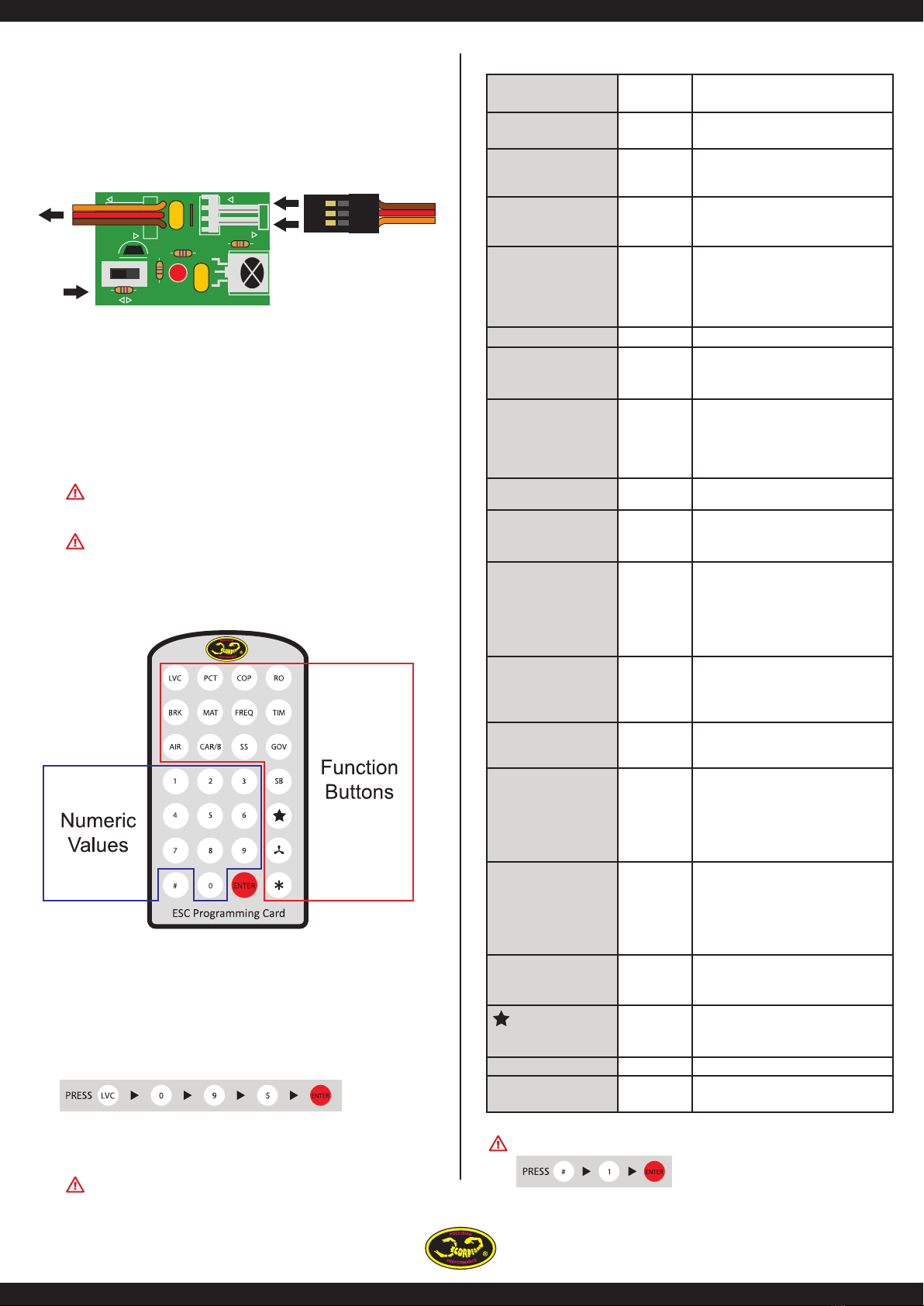
3.0 Scorpion Commander features
ALL Scorpion ESC programming features are available though
the use of the ESC programming card included with your ESC.
So there is NO NEED to purchase ay other cables or cards to
allow you to program your ESC properly.
Scorpion ESC’s come with default or factory settings which are
recommended for most applications. Programming options can
be changed at the discretion of the user. See section 6.0 for
programming instructions.
2.0 Using your Scorpion ESC
Throttle range setup (full throttle and stop).4.1
Turn on transmitter and set throttle to maximum position
be sure that your throttle is set at 0% minimum throttle
and 100% at maximum throttle.
4.2
Move throttle to minimum position within 10 seconds
and hold throttle at minimum position. Then you will hear
2 beeps indicating minimum throttle position is set and
conrmed. Your ESC will also arm after you have set the
minimum position. You only need to do this once as throt-
tle range will be stored in the memory of the speed
controller. You can reset the throttle range by performing
steps 4.1 to 4.4 again.
4.4
Place the switch on the IR receiver to PPM (see section 5.0)
Connect battery to ESC. After few seconds you will hear 2
beeps come from the motor to indicate you are in throttle
calibration mode and maximum throttle position has
been set. (If at this time, you leave the throttle stick at
maximum position for over 10 seconds, the ESC will reset
itself to Factory default throttle settings).
4.3
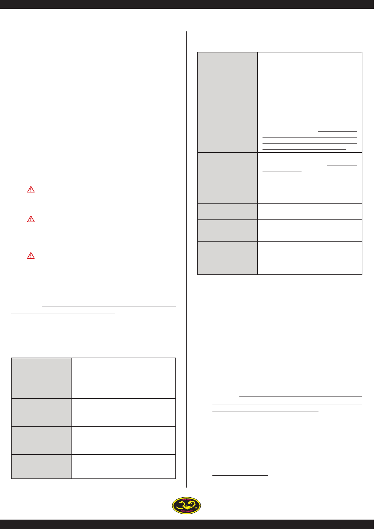
4.0 Initial setup
Safe Power up To arm the controller, the throttle must be
held in the “Brake/Zero” position (all the way
down). If throttle is not at zero at startup, the
ESC will not provide any power to the motor
regardless of where the throttle stick is
positioned when rst powered up.
Loss of signal
(fail safe)
The Scorpion will stop the motor as a safety
feature when the throttle signal is lost or
corrupt for 3 seconds. If a signal is regained
the user will have instant control again.
LED (Only on 26V
Series)
The LED is used for programming /startup
conrmation of your Scorpion ESC. Once
armed the LED can be set to give an
indication of low battery conditions.
Low Voltage Cuto You can choose for your ESC to stop or reduce
power when the input battery voltage drops
to a preset/programmed cuto voltage.
Current Limiting Amp output limit, the output is rated at 10%
over the rated Amp. At approximately 10%
over the rated Amps it will automatically limit
the output to the motor, as long as the motor
is not rated too much over the ESC spec limits,
this safety mechanism will prevent a over
load to the ESC but if you install a motor for
example rated at 100 Amps on a ESC that are
rated for only 60 Amps, this mechanism will
not work properly due to the instant surge of
power demand from the motor, it may
shutdown too early or simply fry the ESC, the
only solution to this is to never use a Motor
that has a rating bigger then the ESC, don’t
even think you can use it if you run the motor
at a slower RPM or load, it will not work!!
Thermal Protection At 95°C, the ESC will slowdown the power
output to the motor by 50% (the on board
LED will ash red), to re-initiate full throttle
you need to move the throttle stick to idle
position and then the ESC will resume normal
output once you throttle up again. If your ESC
is over 60°C on startup it will not arm red LED
will ash and a DI DI DI sound will be played.
Brake Stops rotation of the motor when the throttle
signal is moved to the lowest position.
Throttle Airplane and Heli modes come
pre-programmed and can be selected by the
user.
Electronic timing Manual settings that may improve the
eciency of the system for some motors are
available. The standard Scorpion setting is to
automatically detect and adjust for the motor
it is driving.
You MUST perform throttle range setup before the rst use of
the ESC. Remove propeller/pinion from motor while performing
initial throttle range setup.