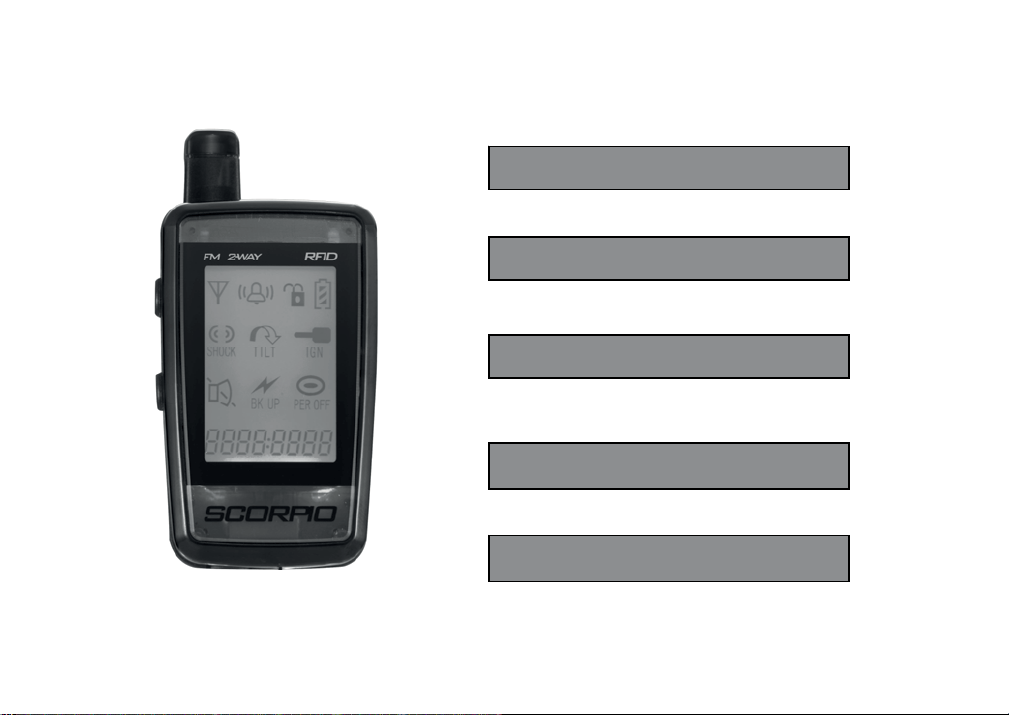
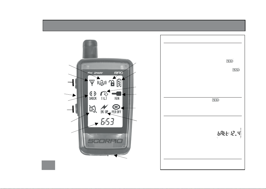
SCORPION SR-i900 Series User manual

Installation
User’s Guide
Transceiver Information
Optional Accessories
A
ppendix

1
Installation
Component List 3
Planning the Installation 3
Installation Diagram 4
Installation Warnings and Notes 5
Mounting the Components 5
Routing the Antenna Wire 5
Making Connections 5
Color Code Chart 6
Using the T tap Connectors 6
User’s Guide
Remote Transceiver Icons
and Message Display 7
Transceiver Charging Instructions 7
Transceiver Battery Status 7
Motorcycle Battery Status 7
Transceiver Back Light 7
Operating Instructions 8
Auto Arm 8
Activate Perimeter Sensor 8
Panic / Stop Trigger 8
Auto Disarm 8
Manual Disarm 8
Manual Arm 8
Programming and Customizing
Instructions 9
Entering Programming mode 9
Selecting Perimeter Sensor Default 9
Selecting Transceiver Alert Type 10
Adjusting the Accelerometer 10
Selecting Siren Default 11
Setting the Clock 11
Encoding the Transceiver 12
Additional Information
Sensor Memory display 13
Motorcycle battery safeguard 13
Table of Contents

2
Manual Override Procedure
Programming Personal
Override Code 14
Enter Programming Mode 14
Select number of flashes for Code 14
Using Code in case of lost remote 14
Transceiver Information
Alarm Triggers 15
Range Confirmation Signal 16
Checking Violation Display 16
Transceiver Battery Information 17
Low Battery Stages 17
Optional Accessory Instructions
Perimeter Sensor (SN 5) 19
Back up Battery 20
Ignition Disable / Anti hijack Unit 21-22
Appendix a1Trouble Shooting guide

3
Components
Component Check List
TRS-9
MCM-9
RFID antenna
AC Adapter
GEN-1(Bag)
T-taps x4
ACC-1(Bag)
Velcro Pieces x2
Zip Ties x4
Dust Cap x1
HAR-1 (Bag)
Planning the Installation
Check that your motorcycle battery is fully charged.
Check the layout of the motorcycle for placement of components.
Verify that no moving parts interfere with the components or their wires.
Verify that chosen location is not near extreme heat.
TRS-9
Transceiver
MCM-9
GEN-1
ACC-1
HAR-1
A
C
Adapter
Installation
RFID
antenna

4
--------------------- Installation Diagram --------------------

Extension 12”
A
ntenna 6”
5
: Connect the (HAR-1) harness to the MCM only after installation is completed. Make sure remote is
closed to bike to avoid a tri
gg
er.
Note: When the main harness (HAR-1) is plugged in, the siren should chirp. If the siren does not chirp; check
the alarm inline fuse, connection to battery
(
+
)
,and connection to
g
round
(
-
)
.
: If the battery is to be removed, disconnect HAR-1 connector first. Reconnect only after battery terminals
are reconnected.
Installation Warnings and Notes
Mounting the Components
Select a suitable location underneath the seat or in a side cover. Mount components using velcro
or cable ties. Make sure that the components are not exposed or accessible.
oPlace MCM as flat as possible to achieve best performance.
oPlace RFID antenna under seat or tail section, do not chose a location that is covered with metal.
Routing the Antenna Wire
For best performance the last 6” of the antenna should:
oBe as vertical as possible.
oBe away from metal as much as possible.
Making Connections
The necessary connector or wires are found under the seat or in the tail section of the bike.
Removal of the tail section plastics or side cover might be necessary.

6
Color Codes: (Color codes are not always valid. Always verify before making connections)
Ground (-) Tail Light Left Turn Signal Right Turn Signal
Honda Green Brown Orange Blue
Kawasaki Black Red Green Grey
Suzuki Black/White Brown Green or Black Grey
Yamaha Black Blue Green Brown
Harley Davidson Black Blue Brown Purple
Ducati Black Yellow White/Black White/Green
Using the T-tap Connectors and GEN-1 Connector
1) Place the female T-tap connector over wire, close and squeeze until it snaps.
2) Slip male T-tap connector over hinged end of the female connector to make a connection.
Motorc
y
cle Wire
Female T-ta
p
1
)
Motorc
y
cle Wire
Wire from (GEN-1
)
Female T-ta
p
Male T-Tap (GEN-1
)
--------------------- Skip this page if using Factory Connector Kit --------------------
2)

Battery
Shock
Trigger Perimeter
Trigger
24 hour
Clock / Text
display
Range
Indicator
Alert Type
Aud/Vibr
System Status
Button 2
Button 1
Tilt Trigger
Ignition
Trigger
Back up
Power
Trigger
Audible/
Silent
Alert Indicato
r
7
Reset
Button
Charger Input
Charging Instructions
We recommend that the transceiver be charged
for up to 12 hours to insure full life of the battery.
1. Plug in provided charger into the transceiver.
2. While the transceiver is charging the
icon will scroll from empty to full.
3. When the transceiver is fully charged the
icon will no longer scroll.
It’s recommended to recharge the transceiver
every day to maintain full function.
Remote Battery Status
The LCD will display 3 different icons to
show the transceiver battery status.
Motorcycle Battery Status
Every time the alarm is activated or deactivated,
the LCD will display a text message with the
current battery voltage.
If motorcycle battery drops below 11 volts the
screen will display CyCLE bAtt LO.
Transceiver Back light
From the main screen pres button 1or 2, the
screen back light will turn on for 2 seconds.
User’s Guide

8
Operating Instructions
The SR-i900, by default, will be in auto arm mode and will activate with the perimeter sensor off and
the siren on, five seconds after turning the ignition key off.
Auto Arm
Activate perimeter sensor
Panic / Stop Trigger (when system is armed)
Auto Disarm
Manual Disarm
Manual Arm (system has to be manually disarmed first)
Walk next to
bike. Turn ignition
key on
Siren:
Chirp 3 Times
Turn Signals:
Flash 1 Time
Siren:
Chirp 1 Time
Turn Signals:
Flash 1 Time
Turn ignition key
off. Walk away
from bike
Press and hold
button 1 Siren:
Chirp 3 Times
Turn Signals:
Flash 1 Time
Siren:
Chirp 1 Time
Turn Signals:
Flash 1 Time
Press and hold
button 2
Note: If the system is manually disarmed it will stay
in disarmed mode. At this mode the system
will not auto arm upon turning ignition key off.
Siren:
Chirp 4 Times
Turn Signals:
Flash 1 Time
Press and hold
button 1 and 2
Siren:
Chirp 6 Times
Turn Signals:
Flash 1 Time
Press and hold
button 1

Press button 2
again to scroll
through
programmable
options
Press button 1 to
scroll between the
options
Programming and Customizing Instructions
Entering Programming Mode
Selecting Perimeter Sensor Default
Enter programming mode. The icon will begin to flash, press button 1 to enter the perimeter
sensor menu. The LCD will display the current setting. To program follow these steps:
Press button 1
to select icon
and to begin
programming
Programmable
options will be
displayed.
The selected
icon will flash
Note. Remote will time-out of programming mode after 20
s
econds. No chan
g
es will be saved.
Press button 2
Twice quickly
to enter
programming
mode
1) 2)
3)
Press
button 2 to
save and
exit
PEr: on – Perimeter sensor will be
enabled every time alarm is
armed
PEr: oFF – Perimeter sensor will be
disabled every time alarm is
armed
9
Note. To exit programming mode scroll through all icons once.

10
Press button 1 to
scroll between the
options
Press button 1 to
scroll between the
options
Selecting Transceiver Alert Type (Audible/Silent/Vibrate)
Enter programming mode. Scroll to the the icon, press button 1 to select. The LCD will display
the current settings. To program follow these steps:
Adjusting the Accelerometer (Shock/Tilt) Sensor (proximity to MCM required)
Enter the programming mode. Scroll to the icon and press button 1 to select. The screen will
display the current shock setting, and the siren will chirp 1-5 times to confirm sensitivity level. To
program follow these steps:
Press
button 2 to
save and
exit
Press
button 2 to
save and
exit
–Transceiver will vibrate and
sound when a trigger occurs
ALL oFF – Transceiver will only flash
backlight when a trigger occurs
– Transceiver will only sound
when a trigger occurs
–Transceiver will only vibrate
when a trigger occurs
Off – Sensor turned off
1 – Least sensitive
5 – Most sensitive

Press button 1 to
scroll between the
options
Press button 1 to
adjust each
digit
Press button 2 to
toggle between
digits
Press
button 2
pass last
digit to
save
11
Selecting Siren Default
Enter programming mode. Scroll to the icon and press button 1 to enter the siren menu. The
LCD will display the current setting. To program follow these steps:
Setting the Clock
Enter the programming mode. Scroll to the time and press button 1 to select. The screen will display
time with the hour flashing. To program follow these steps:
Press
button 2 to
save and
exit –Siren will sound and turn
signals will flash every time alarm is
triggered
–Siren will not sound and
turn signals will not flash every time
alarm is triggered
Note. Clock onl
y
dis
p
la
y
s in 24 hour format
(
Militar
y
time
)

12
Button 1
Encoding a Transceiver
1. Unplug HAR-1 from the MCM-9 and plug it back in, the siren will chirp 2 times and the lights
will flash 2 times.
2. Within 6 seconds of plugging in the HAR-1 turn ignition switch “ON” and “OFF” 3 times.
3. If step 2 is done correctly and within the time allowed , the siren will chirp 2 times and the
lights will flash an additional 2 times to confirm that the system is in “Learn Mode”.
4. Press and hold button 1 until the system chirps 2 times and the lights flash 2 times to
indicate that the MCM has learned the code. The transceiver echoes 4 chirps and the LCD
displays [LErn donE]to confirm that the transceiver is encoded.
5. If you are encoding a second transceiver repeat step number 4 for the second transceiver
before continuing to step number six.
6. Turn ignition “ON” and “OFF” to exit “Learn Mode”.
Note: The transceivers are programmed from the factory. Encoding is only necessary should
the transceiver lose its code and will not arm or disarm the security system or if a second
or re
p
lacement remote is obtained.

13
Sensor Memory Display
When the system is disarmed the turn signals will flash to indicate if there has been an alarm trigger.
The lights will flash once to indicate that the system has been disarmed, additional flashes indicate
that the following trigger has occurred:
1 flash then 1 additional flash = Shock Trigger
1 flash then 2 additional flashes = Tilt Trigger
1 flash then 3 additional flashes = Perimeter Sensor Trigger
1 flash then 4 additional flashes = Back-Up battery Trigger
1 flash then 5 additional flashes = Ignition Trigger
Motorcycle Battery Safeguard with “sleep mode”
xIf the optional perimeter sensor is being used and the alarm is armed for more then 10 days the
system will automatically disable the perimeter sensor.
xIf the alarm is armed for more than 30 days, the system will automatically shutdown its RF
capabilities. In this mode the transceiver will no longer be able to operate the system but the
system is still armed and protecting the bike.
xTo disarm, trigger the alarm, and press button 2.
A
dditional Information

14
Programming Personal Override code (This feature will work on most but not all bikes)
A personal override code will be a sequence of left – right - left turn signal flashes that can be used if
the remote is lost to disable the alarm:
Enter programming Mode
1. Manually disarm system
2. Turn ignition on – off – on – off – on. The siren will chirp one time to confirm.
3. Press and hold button 1 and 2 at the same time for a few seconds until alarm chirps 3 times
and flashes lights 3 times to confirm.
Select number of flashes for Code
The code will be a combination of left-right-left-right turn signal count.
1. Turn on left turn signal to desired number of flashes. (up to 9)
2. Turn on right turn signal to desired number of flashes. (up to 9)
3. Turn on left turn signal to desired number of flashes. (up to 9)
4. Turn on right turn signal once to exit mode. (Will only register one flash)
5. When done, the remote will display the sequence on the screen
until a button is pressed or for up to 30 seconds.
6. The bike will flash the code in the same sequence entered.
Using code in case of lost remote
1. Turn ignition key to on position. Let alarm go thru a full cycle until the turn signal lights stop
flashing. (If siren is turned off, you do not need to wait for a full cycle)
2. Enter code as originally entered.
3. When correct code is entered the alarm will deactivate
Manual Override Procedure
(LCD screen will confirm code)

15
Alarm Triggers
When the system is triggered, the siren will sound and the turn signal lights will flash. The transceiver’s
LCD will display the following messages:
1. If bike is bumped, the LCD will displayicon. The siren on the bike will sound for 5
seconds and the lights will flash. This cycle will repeat twice.
2. If the perimeter sensor triggers a full alarm cycle, the LCD will displayicon. The siren on
the bike will sound for 5 seconds. This cycle will repeat twice
(Note: The turn signal lights will not flash for a perimeter sensor trigger).
3. If the bike is tilted, the LCD will display icon. The siren on the bike will sound for 30
seconds and the lights will flash. This cycle will repeat six times.
4. If the ignition switch is turned on or tampered with, the LCD will display Icon. The siren on
the bike will sound for 30 seconds and the lights will flash. This cycle will repeat six times.
5. If the main harness or battery power supply is disconnected (assuming optional Back-Up
battery is installed), the LCD will display icon. The MCM-9 will still continue to sound
and transmit from its internal power source. The siren on the bike will sound for 30 seconds.
This cycle will repeat six times.
6. The transceiver will continue to flash the triggered icon until any button is pressed.
Transceiver Information

16
RCS (Range Confirmation Signal)
If the transceiver is within range of the MCM and the alarm is activated, the LCD will display icon.
If the transceiver does not receive the RCS; the icon will not appear.
Checking Violation Display with Time Stamp
Press button
1 twice
quickly
If no alarm triggers in memory, all
sensor icons will be displayed If the system was triggered, the last triggered
sensor will be displayed
Trigger # Total # of
Triggers Time of trigger
Press button 1 to scroll
between triggers
Or, press and hold button 2 for
two seconds to erase memory.

17
Transceiver Battery Information
The receiver consists of two functions RFID functions and Two-way FM communication.
Low Battery Stages
It’s recommended that the transceiver be charged daily. If the transceiver is not charged daily the
following stages will occur.
Low Battery: When the battery is low the icon will cycle from 3 bars to 2 bars to 1 bar.
The transceiver should be charged as soon as possible.
Two-Way Off: If the transceiver is not charged, at some point (approximately 7 days) Two-way
communication will shut off. At this mode the LCD displays [rFId onLy]. The RFID
system will still operate and you will still be able to automatically and manually
arm and disarm the system.
No Response: If the battery is not recharged and all power is drained. The transceiver will not
respond. The transceiver has to be charged before it can operate the system
again.

Optional Accessories:
Perimeter Sensor (SN-5)
Back-up Battery (BAT-5)
Ignition Disable (RID-5)
Table of contents
Other SCORPION Motorcycle Accessories manuals

SCORPION
SCORPION RKA-88 User manual

SCORPION
SCORPION EXO-AT950 User manual

SCORPION
SCORPION Commander Series User manual

SCORPION
SCORPION RKT-89 User manual

SCORPION
SCORPION SIGS39 User manual

SCORPION
SCORPION RHA-188 User manual

SCORPION
SCORPION RBM-69 User manual

SCORPION
SCORPION RTR-75 User manual

SCORPION
SCORPION EXO-700 User manual

SCORPION
SCORPION RTR-87 User manual

SCORPION
SCORPION Exo-GT3000 User manual

SCORPION
SCORPION SIGS39 User manual

SCORPION
SCORPION Exo-R410 User manual

SCORPION
SCORPION RKT-72 User manual

SCORPION
SCORPION Commander ESC's Series User manual

SCORPION
SCORPION TR-1001 User manual

SCORPION
SCORPION EHA-95 User manual

SCORPION
SCORPION Exo-CT220 User manual