Se-Kure Controls,®Inc.
3714 Runge Street • Franklin Pk., IL 60131 • 1-(800) 322-2435 • (847) 288-1111 • Fax (847) 288-9999
© 1998 Se-Kure Controls,®Inc. Rev. 6/25/98 SCI-9611
VERY IMPORTANT! Clean the area on the product and the bottom of the sensor with
Alcohol Prep Pads. While the alcohol is still wet, Wipe These Surfaces DRY with a clean
paper towel. If the paper towel shows dirt, REPEAT THE CLEANING STEP until the
surfaces are Clean & Dry!
8. Remove the backing sheet from an adhesive and apply it to the bottom of the sensor.
PRESS it FIRMLY into place to form a good bond.
9. Remove the second backing sheet, and apply
the sensor to the merchandise on the area cleaned
for the sensor. PRESS it FIRMLY into place to
form a good bond.
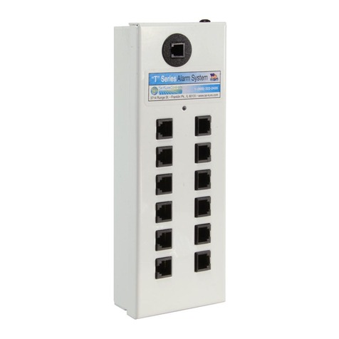
10. Plug the sensor into one of the (12) sensor ports of the T12 Alarm Module. Continue applying sensors to merchandise, and
plugging them into the Alarm Module, you may use all (12) ports to secure items.
11. Turn the key to the LEFT “ON” position. The T12 Alarm Module will now independently scan the (12)
sensor ports for tampering. The unit also continually checks the AC and battery powered condition with a GREEN light to show it
is operating.
Tampering is the removal of Sensors from the Alarm Module, from Merchandise, Inserting Metal Objects into Open Sensor Ports,
or the attempt to short out a Sensor.
12. To Add or Remove Sensors: Insert the key into the lock and turn it to the RIGHT “Stand-By” position. While the unit is in
the “Stand-By” mode, it will “BEEP” once every (30) seconds to warn employees to turn the unit back on.
13. To Re-Set the T12 Alarm after an Alarm: Insert the key into the lock and turn it to the RIGHT “Stand-By” position.
NOTE: During the “Alarm Mode” and after the key has been turned to the “Stand-By” position, the RED indicator lights will con-
tinue to flash, indicating which sensor caused the alarm. Correct the problem/sensor that caused the alarm and turn the key back
to the LEFT “ON” position. The T12 will always search through its ports and check battery condition when turned to the “ON”
position.
SPECIAL NOTE: When using Sensors or Electronic Pucks Without LED Lights:
you must confirm that the sensor or puck has been properly installed.
LED LIGHTS NEXT TO SENSOR PORTS
This Light Will:
• Stay Lit when installed properly
• Flash when the unit is in the Stand-By Mode
If This Light is Not Lit or Flashing when
the unit is in the Stand-By or Armed Mode:
• Remove and re-attach the sensor
If This Light is Not Lit or Flashing with an
Elecetronic Puckattached to the port:
• Follow the procedure at right
SK-905
Rectangular
Adhesive Pads Remove adhesive backing
Place the Alarm Module in
the Stand-By Mode.
If the sensor port is not lit:
• Turn the tripod security screw 1/4 turn until
the sensor port light begins to flash
• Reactivate the Alarm
