SEA VELA RAP 11705010 User manual
VELA RAPIDA
INSTALLATION MANUAL
BARRIER Mod. : “VELA RAP
11705010”,”VELA RAP 11705011”, “VELA
RAP 11705110”,“VELARAP 11705111”
Cod. 67410290 Rev. 02 , 05/2001
D.D.M.T.A.T.GiampieroScarpone15/02/00
Sea s.r.l. is happy to congratulate and thank you for choosing our product. Your choice
will allow you to understand how our factory, according to studies, research and above
all the needs of our clients, wants to gather technology, reliability and safety together
keeping in mind use and installation easiness.
General characteristics
VELA Rapid is a hydraulic barrier (2 -2.5 - 3 m) for the automation of all those
entrances where intensive cycles and high opening/closing speed are necessary
(parkings, motorways, airports ...). It is provided with an anti-crush device that ensures
a strength not higher than 15 Kg on the beam so to ensure people and things against
accidents. An accurate slowing down system guarantees the total control of the
momentum strength. The manual release makes the beam independent from the
hydraulic unit so to allow the manual closing and opening.
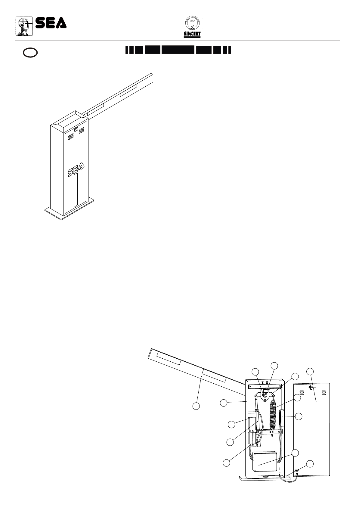
The automation is constituted by:
1Limit Switch cam, with the aim of operating the micro switch intervention.
2Micro Switch for limit switch, which allows to regulate the system slowing down time.
3Steel beam balance assembly coated with zinc.
4VELARapid case lid provided with lock with personalized key from 1 to 32.
5Balancing spring which is available in 2 different sizes so to accomplish with the 3 beam lengths (See spring tab.).
6Electro-fan.
723010016 electronic control unit, an advanced device which allows for the programming and control of all working and
safety systems.
8Mounting plate built with steel coated with zinc.
9Sensor for hydraulic unit temperature monitoring and starting up cooling fan.
10 Double effect hydraulic piston wich gives movement to the beam by the beam balance assembly.
11 Hydraulic unit with manual release for the manual opening of the beam in case of damages and two screws for couple
adjustment.
12 Vela Rapid case wich protects all mechanic and electric devices from atmospheric agents. It is made by a steel sheet
wich is processed with cathaphoresis and epossidic dust painting. On request SEAprovides the inox steel case.
13 Beam in extruded aluminium, available in 3 sizes: 2, 2.5 and 3 m.
11
22
33
44
55
66
77
88
99
1010
1111
1212
1313
Name of the most important parts:
1 Limit Switch cam
2 Micro Switch for Limit Switch
3 Beam balance assembly
4 Vela Rapid case lid
5 Balancing spring
6 Electro-fan
7 23010016 Electronic Control Unit
8 Vela Rapid mounting plate
9 Temperature sensor
10 Piston
11 Hydraulic pump unit
12 Vela Rapid case
13 Aluminium beam
Sistemi elettronici
di Aperture Porte e Cancelli
SEA S.r.l.
DIREZIONE E STABILIMENTO:
Zona industriale 64020 S.ATTO Teramo - (ITALY)
Tel. 0861 588341 r.a. Fax 0861 588344
http://www.seateam.com
9001
CE
GB English

Voltage supply
Absorbed current
Motor power
Motor revolutions
Operating temperature
Thermal cut out
Pump rating
Opening\closing time
Protection class
Manual release device
Use frequency
Capacitor
Hydraulic piston
Anti-crush system
Lock system
Slowing down
Cooling system
Fan intervention temperature
Hydraulic oil
Operating pressure
Max pressure
Barrier case treatment
Beam length
Weight
Electronic Control Unit
: 230 Vac ± 5% - 50/60 Hz single phase
: 1,8 A
: 320 W
: 2800 RPM/min.
: -25 + 70°C
: 130°C
: 2 l./min.
: 1,6 s
: IP55
: Hydraulic
: 100%
: 35 uF 450V
: d 35mm
: No. 2 by-pass valves
: Opening and closing hydraulic one
: Hydraulic
: By forced air with electro-fan
: 65°C 55°C(OFF)
: SEA Verde
: 20 bar
: 50 bar
: cathaphoresis and epossidic dust painting RAL3000
: 2 - 2,5 - 3 m
: 65Kg
: for Rapid barrier (Cod.23010016)
Technical data:
BEAM TABEL
Beam Length
L (m)
2
2,5 - 3
Spring
6
6,5
Spring code
66400050
66400055
Dimensions:
Cod. 67410290 Rev. 02 , 05/2001
30
3
250
1000
320
00
4
765
5
28
L
Beam
25
85
2
3
1) Position of spring and piston
The versatile barrier you are going to install allows for left or right closing
according to requirements. To make sure that the barrier closes your
desired side open the carter and check that the piston is on the side you
like.
Ex. With right hand piston the closing is on the right (Fig 1 and 2).
If the barrier provided does not close your desired side you can invert it
following the instructions we are going to provide.
Fig.1
Right hand closing barrier
Fig.2
Left hand closing barrier
FITTING INSTRUCTIONS
Sistemi elettronici
di Aperture Porte e Cancelli
SEA S.r.l.
DIREZIONE E STABILIMENTO:
Zona industriale 64020 S.ATTO Teramo - (ITALY)
Tel. 0861 588341 r.a. Fax 0861 588344
http://www.seateam.com
9001
CE
Ex. With right hand piston the closing is on the right.
"Remove the spring and piston fixing screws.
"Remove the bracket by unscrewing the bolts
shown.
"Position the piston on the right hand side (where the
spring is fixed) and fix it to the beam balance assembly
by the screw.
"Position the spring on the left hand side (where the
piston is fixed) and fix it to the beam balance assembly
as well.
"Fix the bracket where it was placed before, keeping
in mind that the external holes are for the spring
anchorage pin, while the internal ones are for the piston
pin, both in case of necessity of right closing, and in
case of necessity of left closing.
Cod. 67410290 Rev. 02 , 05/2001
Piston fixing
screws
Spring fixing
screw
Fig.3
Bracket fixing
screws
Anchorage
pins
ConcreteConcrete
Foundation plate to
be levelled
Foundation plate to
be levelled
Clamps 60°~
Clamps 60°~
Wire sheathingWire sheathing
600600
400
400
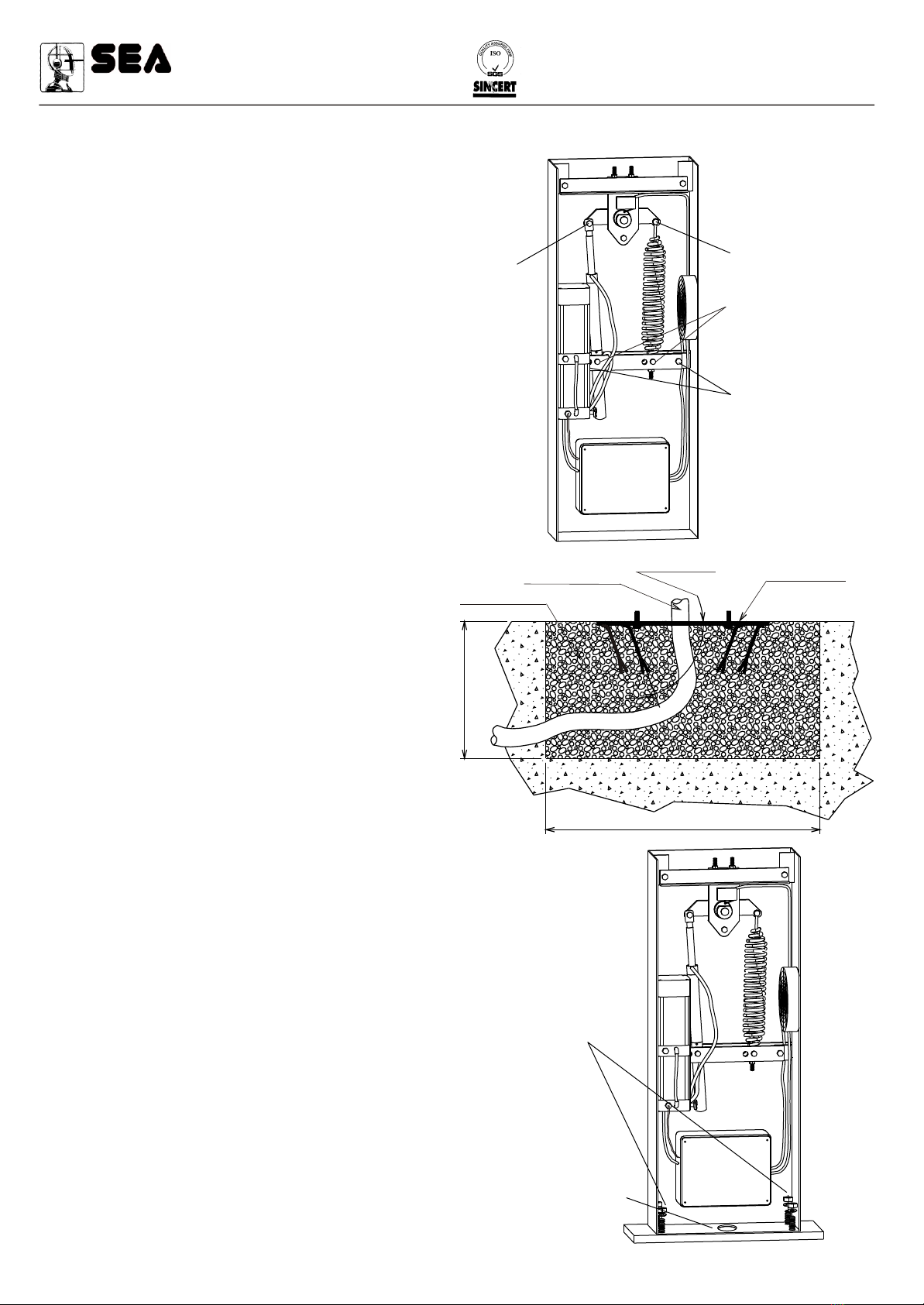
2) Mounting plate fixing
-Dig a hole 600x600x400 mm.
-Widen the foundation plate clamps at 60° (Fig. 4).
-Fill the hole with R425 concrete and place the
foundation plate as in Fig. 4 .
-Level the plate with care.
*The plate has got a central hole for electric wiring so
put an electric wire sheathing in the hole before filling the
hole with concrete.
Fixing nuts
& bolts
Hole for wire
sheathing Fig.5
Fig.4
3) Fixing the column on the foundation plate
-Place the column so that the holes at the base correspond
to the screws that emerge from the foundation plate.
-Make sure that the wire sheathing is fixed on the big
central hole at the base of the column.
-Tighten the column to the foundation plate screwing the
provided nuts and bolts with care.
Sistemi elettronici
di Aperture Porte e Cancelli
SEA S.r.l.
DIREZIONE E STABILIMENTO:
Zona industriale 64020 S.ATTO Teramo - (ITALY)
Tel. 0861 588341 r.a. Fax 0861 588344
http://www.seateam.com
9001
CE
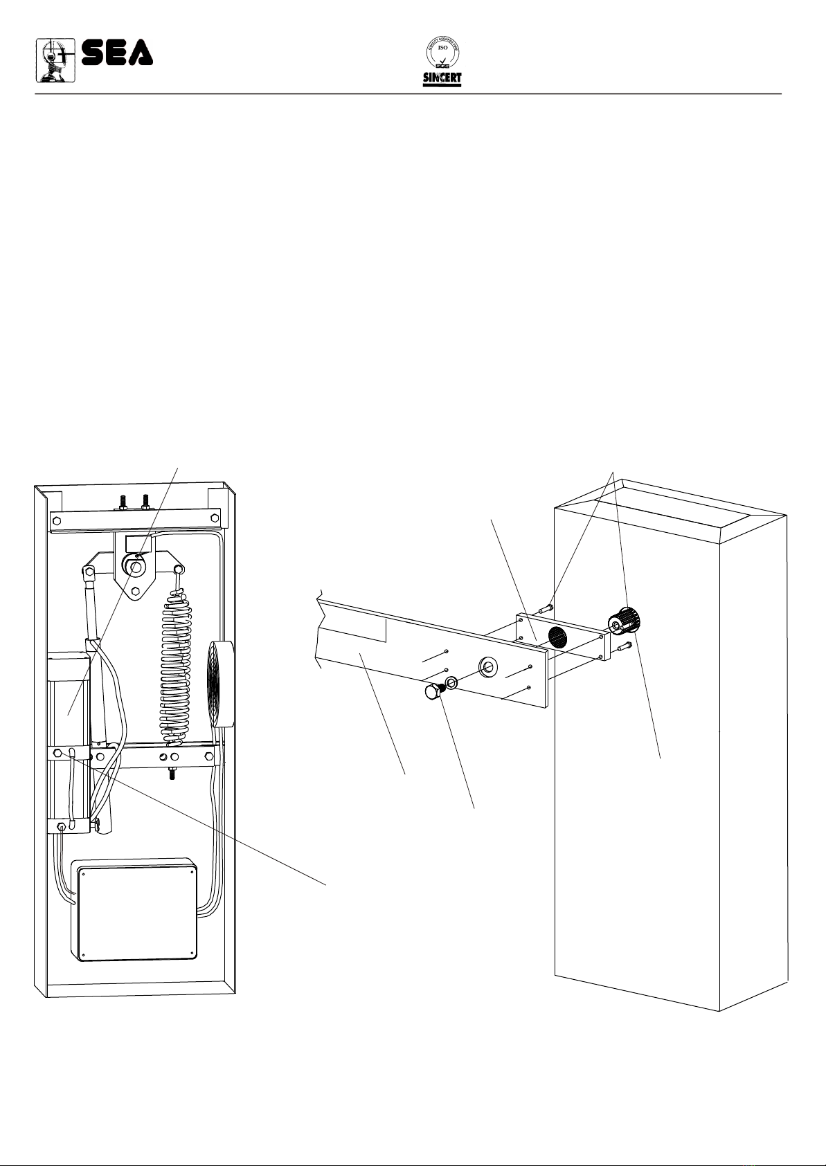
4) Oil Filler plug
When the barrier has been bolted down to the ground remove the oil reservoir transport plug from the frontal part of the
hydraulic pump unit (Fig.6) and replace it for the breather plug supplied with the system.
5) Mounting the beam
-Insert to one end of the splined shaft the beam perfectly vertically positioned.
-Fix the beam using the bolt and washer supplied (Fig. 7).
N.B.: The beam is supplied with the anchorage bracket already fixed. Should that not be the case, fix it by the screws supplied.
Cod. 67410290 Rev. 02 , 05/2001
Oil filler plug
to be replaced by
the breather cork
before working
Hydraulic pump
Bracket for
beam fixing
Screws for
bracket/beam fixing
Splined shaft
Tightening screw
and washer
Beam
Fig.7
Fig.6
Sistemi elettronici
di Aperture Porte e Cancelli
SEA S.r.l.
DIREZIONE E STABILIMENTO:
Zona industriale 64020 S.ATTO Teramo - (ITALY)
Tel. 0861 588341 r.a. Fax 0861 588344
http://www.seateam.com
9001
CE

Cod. 67410290 Rev. 02 , 05/2001
6) Balancing the spring
-Turn the manual release valve anti-clockwise to
release the hydraulic locking so that the beam can
be opened and closed manually.
-Lift the beam to an angle of approximately 45
degrees.
-Tight or untight the spring adjusting bolt locknut so
that the spring reaches a balance point with the
0
beam at 45 (Fig 8). If the beam is correctly
balanced it should stay stopped in position
(Fig.8).
-After balancing fix the spring adjusting bolt
locknut with the bolt and block the hydraulic unit.
7) Slow down adjustment: hydraulic
Spring tension
adjusting bolt
Spring bolt locknut
Hydraulic pump
manual release
Fig.8
Hydraulic pump unit
45
45
15
15
Cam adjusting screws
Fig.9
8) Barrier power supply
You can now feed the barrier with 230Vac 50/60 Hz power supply.
Check “Wiring the connectors” (paragraph 12) for more details.
9) Force adjustment
If necessary the piston force can be adjusted by the two adjusting
screws (grey to open and yellow to close) placed on the front lower
place of the hydraulic pump unit (Fig. 9).
*The automation is adjusted at 15 Kg force ex works so to guarantee
the anti-crush safety. We recommend to adjust it only in case of
necessity.
Sistemi elettronici
di Aperture Porte e Cancelli
SEA S.r.l.
DIREZIONE E STABILIMENTO:
Zona industriale 64020 S.ATTO Teramo - (ITALY)
Tel. 0861 588341 r.a. Fax 0861 588344
http://www.seateam.com
9001
CE

Cod. 67410290 Rev. 02 , 05/2001
10) Levelling the beam
This manoeuvre must be done only if the beam is not perfectly horizontal in closing or vertical in opening at the end
stroke.
-Unlock the hydraulic unit by the release screw so that the beam opens and closes manually.
-Release the end stroke screws unscrewing the lock nuts on the beam balance assembly (Fig.10).
-Screw or unscrew the end stroke screws so that the beam stays perfectly vertical in opening and perfectly horizontal in
closing (Fig.10).
-After levelling, fix the end stroke by tightening the lock nuts on the beam balance assembly and block the hydraulic unit.
Limit Switch adjustment screws
Tightening bolts
Beam balance assembly
Fig.10
11) Wiring
In Fig. 11 you find the wiring necessary for the barrier installation.
The two numbers placed nearby the electrical cables show their quantity and section.
11
2233
44
55
66
77
88
2x1 3x1
2x1
2x1
4x1
3x1,5
3x1
Legend:
1- Vela Rapid electronic
control unit
2- Photocell (transmitter)
3- Photocell (receiver)
4- Key switch
5- Radio receiver
6- Warning light
7- Push button board
8- Differential switch
Sistemi elettronici
di Aperture Porte e Cancelli
SEA S.r.l.
DIREZIONE E STABILIMENTO:
Zona industriale 64020 S.ATTO Teramo - (ITALY)
Tel. 0861 588341 r.a. Fax 0861 588344
http://www.seateam.com
9001
CE

Cod. 67410290 Rev. 02 , 05/2001
12) Connectors connection
The electronic control unit Mod.23010016 is located inside the box. The panel controls all the device functions. It is
technologically advanced and you will choose the logic function that suits you most.
The electronic control unit is provided of two comfortable plugged-in wiring boards; one for low tension, the other for 230V
power supply.
1 2 3 4 5 6 7 8 9 10 11 121 2 3 4 5 6 7 8 9 10 11 12
Open
Close
Stop
Photo
Safety
End Stroke
0V
+24V dc 300 mA Max
Indicator lamp 24V dc(+)
Max1W
- - - -- - - -
LOW TENSION WIRING BOARD CONNECTIONS
-The safety entrance (8/9 usually closed) if activated inverts temporaneously the beam movement.
-The stop entrance (3/4 usually closed) if activated stops the automation anytime.
-The photocell entrance (9/10 usually closed) if activated while closing inverts the beam movement; if activated while
opening it is ignored.
!In case stop, photocells or safety are not connected it is necessary bridging their wire boards (3/4, 5/6, 8/9). Photocells
wiring boards (5/6) must be bridged even if a photocel plug-in board is being used.
WIRING BOARD 230Vac CONNECTIONS
1 2 3 4 5 6 7 81 2 3 4 5 6 7 8
M1M1
Service relay exit 230V
230V ac
NNFF
230 Vac warning light
with lighting board
(code 23104065 and 23104005)
Motor
Com.
blue
Please note: check the manual “Electronic unit” for more information about programming and working logic.
Sistemi elettronici
di Aperture Porte e Cancelli
SEA S.r.l.
DIREZIONE E STABILIMENTO:
Zona industriale 64020 S.ATTO Teramo - (ITALY)
Tel. 0861 588341 r.a. Fax 0861 588344
http://www.seateam.com
9001
CE

Cod. 67410290 Rev. 02 , 05/2001
WARNING
The electric installation and the working logic choice must be done according to the existing laws. A 6A Fuse (or MCB) and a
16A - 0,030A trip must be incorporated into the source of the gate main electrical supply. Keep the power cables (motors,
power supply) and the control ones (push buttons, photocells, radio etc.) separated. You can use two different sheaths to avoid
interference.
Note: Use “cable clips” and/or “duct/box pipes” fitting close to the control panel box so to protect the interconnection cables
against pulling efforts.
INTENDED USE
The Vela Rapid has been designed to be solely used to automate barriers.
SPARE PARTS
To obtain spare parts contact:
SEAs.r.l. Zona Ind.le, 64020 S.ATTO Teramo Italia
SAFETYAND ENVIRONMENTAL COMPATIBILITY
We recommend not to spoil the environment with product and circuit packing material.
CONFORMITY REQUIREMENTS
The VELARAPID operator conforms to the following:
- 89/392/CEE (Machine Directive)
- 89/336/CEE (Electromagnetic Compatibility Directive)
- 73/23/CEE (Electric Safety)
STORAGE
STORAGE TEMPERATURES
Tmin
-40°C
Tmax
+80°C
Humiditymin
5% no condensation
Humiditymax
90% no condensation
When being transported this product must be properly packaged and handled with care.
MAINTENANCE AND OUT OF SERVICE
The decommission and maintenance of this unit must only be carried out by specialised and authorised personnel.
LIMIT OF GUARANTEE
Vela Rapid is guaranteed for a period of 24 months. The guarantee period starts from the date stamp printed on the unit. The
guarantee will be void if the unit has been incorrectly installed, not used for the purpose intended, tampered with or modified in
any way.
The validity of this guarantee only extends to the original purchaser of the unit.
NOTE: THE MANUFACTURER CAN NOT BE DEEMED RESPONSIBLE FOR ANY DAMAGE OR INJURY CAUSED BY
IMPROPER USE OF THIS PRODUCT.
SEA reserves the right to modify or adjust the products and information provided in this manual with no obligation to
notice.
Sistemi elettronici
di Aperture Porte e Cancelli
SEA S.r.l.
DIREZIONE E STABILIMENTO:
Zona industriale 64020 S.ATTO Teramo - (ITALY)
Tel. 0861 588341 r.a. Fax 0861 588344
http://www.seateam.com
9001
CE
This manual suits for next models
3
Table of contents
Other SEA Control System manuals


Popular Control System manuals by other brands


SIMARINE
SIMARINE SC302T user manual

Elsner
Elsner WS1 Color Brief Instruction

ADB Safegate
ADB Safegate RELIANCE Navigator user manual

Rottler
Rottler F103 Series Installation guide, operation and maintenance manual

Bryan Boilers
Bryan Boilers CL Series brochure

Joyonway
Joyonway PB554 Simplified operation instruction


