SEA TAURUS RACK Series User manual

IORTANT SAETY INORATION
All the aboe described operations must be made eclusiel b an authoried installer
Clean and grease parts in movement wheels,
counter-connecting rod, release, etc.
Check for corroded parts and replace if
necessary
Check if the screws and all mounting
hardwares are properly tighten
Annual
Annual
Annual
Check the conditions of wear and tear of the
devices in movement
Check the correct drain of the rainwater
Check the integrity of the connection cables
Annual
Annual
Annual
Inspect the track for any signs of cracking or
separation
Ensure that the gate moves freely
Annual
Annual
Check and confirm the proper operation of all
safety devices photocells, edge sensors etc
Check and confirm the operation of all
installed accessories
Check and confirm the operation of the
manual release
Annual
Annual
Annual
TURNING ON TE POWER
Check the battery conditions and be sure that
connections are free of corrosion
erify the functionally of the battery backup,
or power failure option
Y MAIN POWER SOURCE TURNED OFF
Annual
TURNING OFF TE POWER
CCCC
GENERAL SAFETY PRECAUTIONS
The following precautions are an integral and essential part of the product and must be supplied to the user Read
them carefully as they contain important indications for the safe installation, use and maintenance.
. These instruction must be kept and forwarded to all possible future users of the system.
2. This product must be used only for that which it has been expressly designed.
3. Any other use is to be considered improper and therefore dangerous.
4. The manufacturer cannot be held responsible for possible damage caused by improper, erroneous or
unreasonable use.
5. Avoid operating in the proximity of the hinges or moving mechanical parts.
6. Do not enter the path of the moving gate while in motion.
7. Do not obstruct the motion of the gate as this may cause a situation of danger.
. Do not allow children to play or stay within the path of the moving gate.
. eep remote control or any other control devices out of the reach of children, in order to avoid possible involuntary
activation of the gate operator.
0. In case of break down or malfunctioning of the product, disconnect from the main power source.
Do not attempt to repair or intervene directly, contact only qualified personnel for repair.
. Failure to comply with the above may create a situation of danger.
2. All cleaning, maintenance or repair work must be carried out by qualified personnel.
3. In order to guarantee that the system works efficiently and correctly it is important to have the manufacturers
instructions on maintenance of the gate and operator carried out by qualified personnel.
4. In particular, regular checks are recommended in order to verify that the safety devices are operating correctly.
All installation, maintenance and repair work must be documented and made available to the user.
IMPORTANT SAFETY INSTRUCTIONS
WARNIN To reduce the risk of inury or death:
. READ AND FOLLOW ALL INSTRUCTIONS.
2. Never let children operate or play with gate controls. eep the remote control away from children.
3. Always keep people and objects away from the gate. NO ONE SHOULD CROSS THE PATH OF THE MOIN ATE.
4.Test the gate operator monthly. The gate MUST reverse on contact with a rigid object or stop when an object
activates the non-contact sensors. After adjusting the force or the limit of travel, retest the gate operator. Failure to
adjust and retest the gate operator properly can increase the risk of injury or death.
5. Use the emergency release only when the gate is not moving
6. EEP ATES PROPERL MAINTAINED. Read the owner’s manual. Have a qualified service person make
repairs to gate hardware.
7. The entrance is for vehicles only. Pedestrians must use separate entrance.
. Every gate operator installation MUST have secondary protection devices agains entrapments, such as edge
sensors and photo beams more in particulary in places where the risk of entrapments is more likely to occur
. SAE THESE INSTRUCTIONS
!
PERIODICAL MAINTENANCE
2

GENERAL SAFETY INFORMATION
An appliance shall be provided with an instruction manual. The instruction manual shall give instructions for the
installation, operation, and user maintenance of the appliance.
The installation instructions shall specify the need for a grounding-type receptacle for connection to the supply and
shall stress the importance of proper grounding.
The installation instructions shall inform the installer that permanent wiring is to be employed as required by local
codes, and instructions for conversion to permanent wiring shall be supplied.
Information shall be supplied with a gate operator for:
a The required installation and adjustment of all devices and systems to effect the primary and secondary protection
against entrapment where included with the operator.
b The intended connections for all devices and systems to effect the primary and secondary protection against
entrapment. The information shall be supplied in the instruction manual, wiring diagrams, separate instructions, or the
equivalent.
Vehicular gate operators (or sstems)
A vehicular gate operator shall be provided with the information in the instruction manual that defines the different
vehicular gate operator Class categories and give examples of each usage. The manual shall also indicate the use for
which the particular unit is intended as defined in lossary, Section 3. The installation instructions for vehicular gate
operators shall include information on the Types of gate for which the gate operator is intended.
A gate operator shall be provided with the specific instructions describing all user adjustments required for proper
operation of the gate. Detailed instructions shall be provided regarding user adjustment of any clutch or pressure relief
adjustments provided. The instructions shall also indicate the need for periodic checking and adjustment by a qualified
technician of the control mechanism for force, speed, and sensitivity.
Instructions for the installation, adjustment, and wiring of external controls and devices serving as required protection
against entrapment shall be provided with the operator when such controls are shipped with the operator.
Instructions regarding intended installation of the gate operator shall be supplied as part of the installation instructions
or as a separate document. The following instructions or the equivalent shall be supplied where applicable:
IMPORTANT INSTALLATION INSTRUCTIONS
a Install the gate operator only when:
The operator is appropriate for the construction of the gate and the usage Class of the gate,
2 All openings of a horizontal slide gate are guarded or screened from the bottom of the gate to a minimum of 4 feet
.22 m above the ground to prevent a 2-/4 inch 57.2 mm diameter sphere from passing through the openings
anywhere in the gate, and in that portion of the adjacent fence that the gate covers in the open position,
3 All exposed pinch points are eliminated or guarded, and
4 uarding is supplied for exposed rollers.
b The operator is intended for installation only on gates used for vehicles. Pedestrians must be supplied with a
separate access opening. The partial access opening shall be designed to promote pedestrian usage. Locate the gate
such that persons will not come in contact with the vehicular gate during the entire path of travel of the vehicular gate.
c The gate must be installed in a location so that enough clearance is supplied between the gate and adjacent
structures when opening and closing to reduce the risk of entrapment. Swinging gates shall not open into public access
areas.
d The gate must be properly installed and work freely in both directions prior to the installation of the gate operator. Do
not over-tighten the operator clutch or pressure relief valve to compensate for a damaged gate.
e The gate operator controls must be placed so that the user has full view of the gate area when the gate is moving and
AWA FROM THE ATE PATH PERIMETER.
f Controls intended for user activation must be located at least six feet 6’ away from any moving part of the gate and
where the user is prevented from reaching over, under, around or through the gate to operate the controls. Outdoor or
easily accessible controls shall have a security feature to prevent unauthorized use.
g The Stop and/or Reset button must be located in the line-of-sight of the gate. Activation of the reset control shall not
cause the operator to start.
h A minimum of two 2 WARNIN SINS shall be installed, one on each side of the gate where easily visible
3

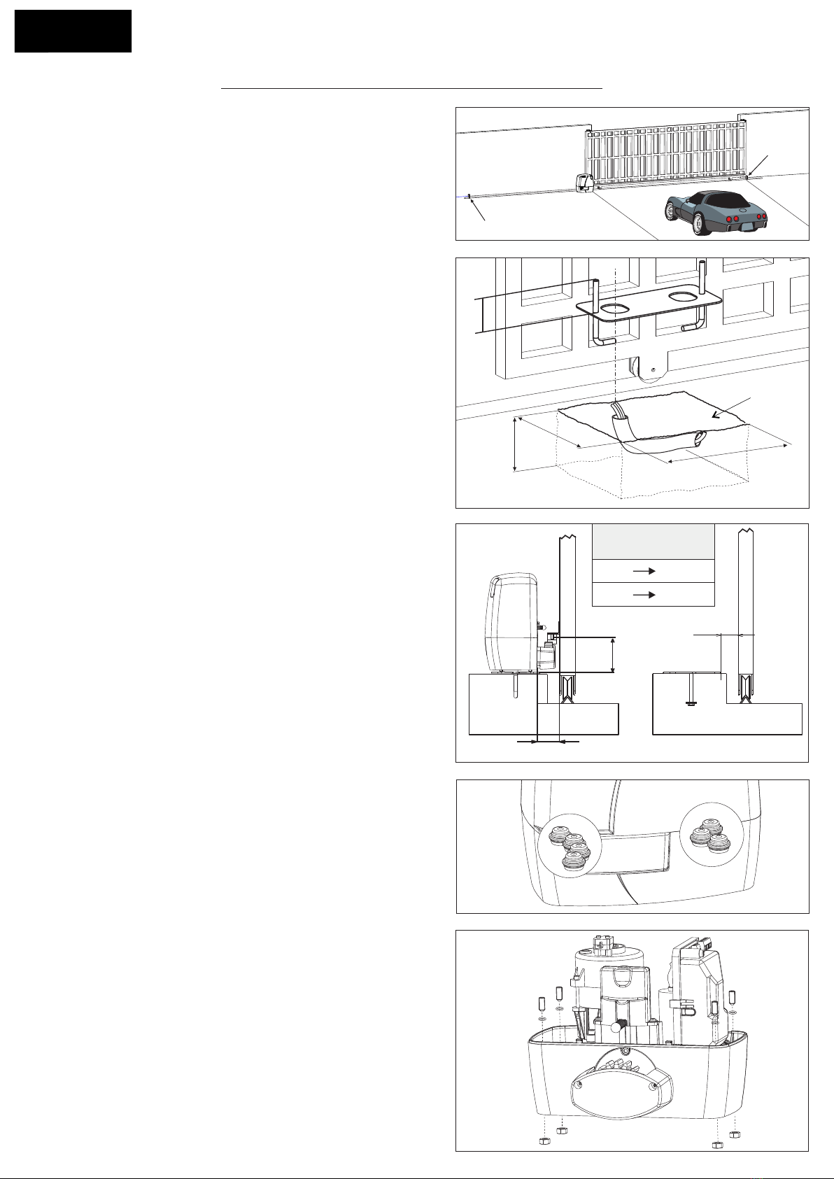
i) For gate operators utiliing a non-contact sensor:
See instructions on the placement of non-contact sensors for each Type of application
2 Care shall be exercised to reduce the risk of nuisance tripping, such as when a vehicle, trips the sensor while the
gate is still moving
3 One or more non-contact sensors shall be located where the risk of entrapment or obstruction exists, such as the
perimeter reachable by a moving gate or barrier
) For a gate operator utiliing a contact sensor:
One or more contact sensors shall be located where the risk of entrapment or obstruction exists, such as at the
leading edge, trailing edge, and postmounted both inside and outside of a vehicular horizontal slide gate.
2 One or more contact sensors shall be located at the bottom edge of a vehicular vertical lift gate.
3 One or more contact sensors shall be located at the pinch point of a vehicular vertical pivot gate.
4 A hardwired contact sensor shall be located and its wiring arranged so that the communication between the
sensor and the gate operator is not subjected to mechanical damage.
5 A wireless contact sensor such as one that transmits radio frequency RF signals to the gate operator for
entrapment protection functions shall be located where the transmission of the signals are not obstructed or
impeded by building structures, natural landscaping or similar obstruction. A wireless contact sensor shall
function under the intended end-use conditions.
6 One or more contact sensors shall be located on the inside and outside leading edge of a swing gate. Additionally,
if the bottom edge of a swing gate is greater than 6 inches 52 mm above the ground at any point in its arc of
travel, one or more contact sensors shall be located on the bottom edge.
7 One or more contact sensors shall be located at the bottom edge of a vertical barrier arm.
Instruction regarding intended operation of the gate operator shall be provided as part of the user instructions or as a
separate document. The following instructions or the equivalent shall be provided
NOTICE
As for misunderstandings that may arise refer to your area distributor or call our help desk. These instructions are part
of the device and must be kept in a well known place. The installer shall follow the provided instructions thoroughly.
SEA products must only be used to automate doors, gates and wings. Any initiative taken without SEA USA Inc. explicit
authorization will preserve the manufacturer from whatsoever responsibility. The installer shall provide warning notices
on not assessable further risks. SEA USA Inc. in its relentless aim to improve the products, is allowed to make
whatsoever adjustment without giving notice. This doesn’t oblige SEA to up-grade the past production. SEA USA Inc.
can not be deemed responsible for any damage or accident caused by product breaking, being damages or accidents
due to a failure to comply with the instructions herein. The guarantee will be void and the manufacturer responsibility
will be nullified if SEA USA Inc. original spare parts are not being used. The electrical installation shall be carried out by
a professional technician who will release documentation as requested by the laws in force. Packaging materials such
as plastic bags, foam polystyrene, nails etc must be kept out of children’s reach as dangers may arise.
To respect the norms in force it is recommended to use the ENCODER SYSTEM together with the electronic
control units
Starting on an. 2, 206, new UL 325 changes take effect, bringing a series of new mandates for the gate operator
industry. Here’s a quick guide to the key modifications.
1. Entrapment-Protection Deices. ate operators are required to have a minimum of two independent means of
entrapment protection where the risk of entrapment or obstruction exists. A manufacturer can use two inherent-type
systems, two external-type systems, or an inherent and an external system to meet the requirement. However, the
same type of device cannot be used for both means of protection.
2. Monitoring Reuired. An external non-contact sensor or contact sensor may be used as a means of entrapment
protection. However, the sensor must be monitored once every cycle for the correct connection to the operator and
2 the correct operation of the sensor.
If the device is not present, not functioning, or is shorted, then the gate operator can only be operated by constant
pressure on the control device. Portable wireless controls will not function in this case.
3. Entrapment Ris Identification. As in the past, it’s up to the installer to examine the installation and determine
where a risk of entrapment or obstruction exists. Manufacturers are required to provide instructions for the placement
of external devices, but they give only examples of suggested entrapment protection in their installation manuals. If the
installer identifies a risk of entrapment or obstruction, at least two independent means of entrapment protection are
required.
4.Terminolog Change. The terms primary and secondary have been removed in the description of entrapment
protection devices. This was done to emphasize that all entrapment protection devices are equally important.
Can L ED a Oa
4

5. The End of Tpe E. Type E audible alarm devices can no longer be used for entrapment protection. This change
was made because the Type E device is really a warning device, not an entrapment-protection device. Also, all gate
operator classes are now required to have an audio alarm that sounds when two successive obstructions are
encountered via a contact-type system.
6. Access Control Location for Emergenc Use. An exception has been added in the manufacturer’s instructional
requirements for the location of controls that operate the gate.
The instructional requirements state that these controls must be at least 6 away from any moving part of the gate. In the
new exception, Emergency access controls only accessible by authorized personnel e.g., fire, police, EMS may be
placed at any location in the line-of-sight of the gate.
7. arrier-Arm Operator Eception. An exception has changed for barrier-arm gate operators requiring entrapment
protection. The previous exception stated that a barrier-arm operator did not require entrapment protection if the arm
did not move toward a rigid object closer than 2. The distance has been reduced to 6 so it more closely aligns with the
industry-defined entrapment protection provisions in ASTM F2200.
8. Gate Operator Class II and Class III Definitions. The definitions for installation classes for gate operators were
modified. Class II now includes commercial locations accessible to the general public. Class III was refined to specify
industrial locations not accessible to the general public. These changes, while seemingly minor, may affect which gate
operator is suitable for a particular installation location.
L ED ENTRAENT ROTECTION REIREENTS
This ehicular gate operator must be installed with at least two independent entrapment protection
means as specified in the table below.
VERITICAL ARRIER NOTE:
arrier gate operators (arm) that is not intended to moe toward a rigid obact closer than 16 inches (406mm)
are not reuired to be proided with a means of entrapment protection
1 and 2 means of entrapment protection MUST be MONITORED
ORIONTAL SLIDE
VERTICAL LIFT - VERTICAL PIVOT
ENTRAPMENT
PROTECTION
TYPES
TPE A
TPE B
TPE B2
TPE C
Inherent entrapment protection system
Non-contact sensors such as photoelectric sensors or equivalents
Contact sensors such as edge sensors or equivalent devices
Inherent force limiting, inherent adjustable clutch or inherent pressure relief device
The same type of device shall not be used for both entrapment protection means. Use of a single device to cover both
the opening and closing directions is in accordance with the requirement however, a single device is not required to
cover both directions. Tice installer is required to install entrapment protection devices in each entrapment zone
TPE D Actuating device requiring constant pressure to maintain opening or closing motion of the gate
SWING
VERTICAL ARRIER (ARM)
A , B, B2 or D A , B, B2, C or D
GATE OPERATOR CATEGORY
Effectie anuar 12 2016
VEICULAR GATE OPERATOR CLASSES
Residential Vehicular Gate Operator-Class I: A vehicular gate operator or system intended for use in garages or
parking areas associated with a residence of one-to-four single families
CommercialGeneral Access Vehicular Gate Operator-Class II: A vehicular gate operator or system intended for
use in a commercial location or building such as a multi-family housing unit ve or more single family units, hotel,
garages, retail store, or other buildings accessible by or servicing the general public
IndustrialLimited Access Vehicular Gate OperatorClass III: A vehicular gate operator or system intended for
use in an industrial location or building such as a factory or loading dock area or other locations not accessible by or
intended to service the general public
Restricted Access Vehicular Gate OperatorClass IV: A vehicular gate operator or system intended for use in an
industrial location or building such as a factory or loading dock area or other locations not accessible by or intended to
service the general public
5

ATE WARNINS AND RECATIONS
PRECAUTIONS
TAURUS has been created for the automation
of sliding gates used by vehicles only. Be aware
to avoid to cross the gate path because it is very
dangerous for pedestrians Fig.. Make sure
that no person could activate the automation
through the gate bars from the outside Fig.
WARNING SIGNS
Install the warning signs on each side of the
gate and in a isible one to inform the pe-
destrians about the danger they run when pas-
sing or standing in the path of the gate Fig. 0
Fig.
Fig. 2
Fig. 3 Fig. 4
Fig. 5 Fig. 6
/2
/4
5”
Fig. 7
!
WARNING
n a Can Ca
S In O Da
- EEP CLEAR Gate ma moe at an
time without prior Warning.
- Do not let children operate the gate or
pla in the gate area.
- This entrance is for ehicle onl.
Pedestrians must use separate entrance
TYPE OF INSTALLATION
Only a head-on installation of the operator is
permitted it is highly recommended to install
two security gate stops on the two extremities of
the rail to prevent the gate from derailment
Fig.
Fig. 0
!
WARNING
n a Can Ca
S In O Da
- EEP CLEAR Gate ma moe at an time
without prior Warning.
- Do not let children operate the gate or pla in
the gate area.
- This entrance is for ehicle onl.
Pedestrians must use separate entrance
Fig.
Oer-Trael Stop
Oer-Trael
Stop
GATE ARRANGEMENT
Check the gate is in good running order as follows:
a) The gate is rigid and straight and runs smoothly throughout its travel
b) The inferior sliding guide-rail is perfectly straight and horizontal to avoid derailment of the gate Fig.
furthermore it must be free of irregularities and foreign bodies which could obstruct the normal run of the gate
Fig. 2 - 3
c) The upper guides are not fixed Fig. 4 but furnished with rollers
d) The distance between the end of the gate in maximum opening position and the eventual wall must be at
least of 5 inches Fig. 7 which allow the sliding of the gate without difficulties Fig. 5 and 6
e) The lower support wheels have sealed bearings or grease points
f) The top guide must be manufactured and installed so that the gate is perfectly upright
g) Physical gate stops must be fitted to prevent the gate coming out of its guides and track
Fig.
Fig.
!
Important: For a higher securit SEA
adices to install infrared photocells
Securit Gate Stop are obligator especiall
in TAURUS without Limit Switch ersion
6

2
13
4
5
6
7
8
TAURUS is a sliding gate operator with grease lubricated gear. The irreersibilit of the motor grants a
perfect and safe gate closing, avoiding the need of an elecric lock. In case of electric power failure, the manual
release handle placed head on the operator allows the manual opening and closing of the gate. The operator
is equipped with an electronic clutch device providing the thrust adjustment on the gate. The electronic
inersion sstem optional through Encoder makes the TAURUS a safe operator in compliance with the
laws in force in the country where the product has to be installed.
TAURUS operator is available in versions WIT LIMIT SWITC OR WITOUT LIMIT SWITC
AIN EATRES
DIMENSIONS (inches)
MAIN COMPONENTS
1 Adjustable foundation
plate
2 Anchor bolts
3 Pinion protection
4 Pinion
5 ear release lever
6 Electronic control unit
7 Magnetic encoder
If present
8 Micro-switch
If present
11.81
6.30
11.81
917
1358
472
The freuenc of use is alid onl for the first hour at 68F room temperature
Fig. 2 Fig. 3
Fig. 4
7,8 In/s (Z16) 11 In/s (Z17)
23 Lb 25 Lb
TAURUS GPLS
1000 - 120V
TAURUS RACK
120V - 24V
120V ± 5% - 50/60 Hz~
TECNICAL DATA
Power supply
Absorbed power
Absorbed current
Opening speed
Motor capacitor
Working frequency
Working temperature
Thermoprotection
Weight
Protection degree
Maximum torque
Gate maximum weight
Gate operator class
Anti-crushing clutch
Limit switch
TAURUS RACK
120V
-4°F +131°F
IP55
15 Nm
1000 Lb
I II III IV
Electronic
Electromechanical (If present)
110W
1,8 A
Adjst. 9 In/s (Z16)
-
40%
-
24 Lb
350W
3,2 A
60 µF
30%
Integrated - 302°F
7

Plinth
Fig. 6
DIMENSIONS
(inches)
2. FOUNDATION PLATE ANCORING
(Only for TAURUS RACK version)
To install the foundation plate proceed as follows:
2.1. Prepare a concret basement with the dimensions
shown in Fig. 6 where the foundation plate and the
anchoring bolts will be cemented.
NOTE: It is recommended gate structure permitting
to lift the foundation plate about ,6 inches from the
ground, in order to avoid eventual water stagnation
2.2. Before cementing the plate insert a flexible plastic
duct of at least , inches in diameter into the special
hole of the plate.
2.3. Before cementing the plate, make sure that it’s
perfectly leveled and that the distance of 2,4 - 2,67
inches as shown in Fig. 7 is respected
1. TYPE OF INSTALLATION
Only a head-on installation of the operator is
permitted it is highly recommended to install two
security gate stops on the two extremities of the rail to
prevent the gate from derailment Fig. 5
Fig. 5
Oer-Trael Stop
Oer-
Trael
Stop
ECANICAL INSTALLATION
590
1653
984
3
Fig. 7
16
20
3,93 in.
4,25 in.
244 in.
248 - 267 in.
«Q» MINIMUN
DIMENSION
Q
3. CALES PASSAGE ARRANGEMENT
TAURUS is provided with seven holes for electric
cables passage.
Important: Always run main carrying cables 20
in separate holes to low voltage cables 24 - Fig.
4. FITTING OF TE MOTOR
(Only for TAURUS RACK version)
4.1. Insert the 4 grub screws into the special holes for
the adjustment of the motor height on the plate
Fig.
At the end of installation check if the 4 grub
screws are well gripped on the foundation plate
4.2. Fix the motor on the foundation plate with the 2
included nuts, adjusting the side position Fig. 20 so
to respect the quota shown in Fig. 7
Fig.
Fig.
8

5. GEAR RAC MOUNTING
(Only for TAURUS RACK version)
5.1. Release the motor and open the leaf completely
5.2. Fix on each gear rack element the support pawls
with the appropriate lock screws, make sure to put
them in the upper part of the hole Fig. 2
5.3. Lean the gear rack element on the toothed pinion
of the motor in parallel to the ground slideway of the
gate, as shown in Fig. 22 and electrically weld the
central pawl to the gate structure Fig. 23.
Manually move the gate until pawl C is placed
corresponding to the pinion and fix it through electric
welding. Repeat the same procedure for pawl A
after having placed it corresponding to the pinion
5.4. Make sure that all the gear rack elements are
perfectly aligned and placed correctly teeth in
phase. It is suggested to place two aligned elements
in front of a third one as shown in Fig. 24
5.5. Repeat the above described operation for all the
remaining gear rack elements which have to be
installed
5.6. To avoid that the door weights down on the pinion
Fig. 25 lift up the whole rack about 0,05 inches
Warning: eep a gap of about 0,0 inches between
pinion tooth and gear rack tooth
5.7. Make sure the gear rack works at the center of
the pinion along all rack elements, if necessary,
adjust the length of the spacers.
Steel rac
(to weld)
Plastic rac
steel core
(to screw)
Fig. 2
Fig. 22
AC
Fig. 23
Fig. 20
Fig. 24
0059
inches
Fig. 25
9

6. ASSEMLING OF TE CAIN SYSTEM
(Only for TAURUS CHAIN version)
The assembling of the main parts which include the
whole chain automation is illustrated in Fig. 26. In the
Fig. 27 and 2 it is possible to see the correct instal-
lation with open and closed gate respectively make
sure the chain runs inside the pinion group which
must not be modified. For a correct installation follow
carefully the indications below:
6.1. Weld two strong pierced brackets to the two
extremities of the gate to couple the chain.
Notice: the holes for the chain tensioner and so
the chain itself must be to a minimum distance of
157 inches from the gate (Fig. 29)
6.2. Install the chain making it pass through the pinion
group as in Fig. 26. The chain must be always in line
both vertically Fig. 27 and orizontally Fig. 2 if not
perfectly aligned Fig. 30 and 3 it may derail from
the pinion group or the motor reducer risks a greater
effort not allowing the right operating of the system.
6.3. Set up a fillet chain tensioner to the two extremi-
ties of the gate to regulate the tension of the chain.
Notice: do this last operation with the engine
completel unloced through the special
unlocing e
Fig. 3
Fig. 2
Fig. 26
Fig. 2
Fig. 30
157
Fig. 27
10

Fig. 32
Limit switch in closing
Limit switch in opening
Mechanical limit switch
Fig. 33
7. LIMIT SWITC ADUSTMENT
For versions «TAURUS WITH LIMIT SWITCH»
7.1. To install and adjust the limit switches in opening
proceed as follows Fig. 32:
- Completely open the gate
- Place the plate on the rack in order to have the lever
of the mechanical limit switch Fig. 33 in correspon-
dance of the limit sheet and fix it with the appropriate
screws Fig. 34.
7.2. To install and adjust the limit switches in closing
the gate must be completely closed.
7.3. By setting the braking trimmer on control unit it is
possible to make the gate stop on the desired position
Fig. 34
8. GROUNDING (Fig. 35)
Fig. 35
9. ELECTRIC CONNECTIONS OF TE
INSTALLATION (Fig. 36)
1
2
3
4
10
5
67
8
9
1) Taurus
2) Photocell S
3) Photocell D
4) Mechanical safet edge
5) e push botton
Fig. 36
6) Flasher
7) Receier
8) Warning notice
9) unction bo
10) Differential
!
CAUTIONS:
The gate must be moed in halfwa position
before starting the self-learning
• On versions «TAURUS WITHOUT LIMIT SWITCH»:
Check the micro-switch inside the slot is correctly
connected to the STOP output on control unit
11

Page for both installer and user
10. RELEASE SYSTEM
10.1 To release proceed as follows:
- Insert the key, push and turn clockwise of about 0
Fig. 37
- Pull the release lever until it stops, of about 0
Fig. 3
Note: when pulling the release leer the electro-
nic control unit receies a stop impulse through
the micro-switch placed on the inside (if present)
10.2. To reloc proceed as follows:
- Push the release lever to complete closing
- Rotate the key counter-clockwise and extract it
Once the lock has been restored the electronic control
unit is reactivated only if a micro-switch is mounted
Fig. 37
Close
Open
Push and
turn
Fig. 3
PERIODIC MAINTENANCE
Annual
Annual
Annual
Annual
Annual
Annual
Annual
Annual
Chec limit switch functionalit and status in opening
and closing and the related small plates
Chec the efficienc of the electronic anti-crushing clutch
Chec the release functionalit
Chec the clutch functionalit (where present)
Chec the distance between pinion and gear rac (0.059 inches)
Chec the usur status of pinion and gear rac
Chec the fiing screws
Chec the connection cables integrit
All the aboe described operations must be done eclusiel b an authoried installer
RIS EAMINATION
The points pointed by arrows in Fig. 3 are potentially dangerous. The installer must
take a thorough risk examination to prevent crushing, conveying, cutting, grappling,
trapping so as to guarantee a safe installation for people, things and animals (Re. Laws
in force in the Country where the installation has been made)
NOTICE
SEA USA Inc. can not be deemed responsible for any damage or accident caused by
product breaking, being damages or accidents due to a failure to comply with the
instructions herein. The guarantee will be void and the manufacturer responsability will
be nullified if SEA USA Inc. original spare parts are not being used. The electrical
installation shall be carried out by a professional technician who will release docu-
mentation as requested by the laws in force. Packaging materials such as plastic bags,
foam polystyrene etc must be kept out of children’s reach as dangers may arise
Fig. 3
WARNINGS The electrical installation and the operation logics must comply with current regulations. eep the power cables
motors, power supply separated from the control cables push-buttons, photocells, radio, etc.. Separate conduits should be used
to prevent noise issues. Note: Use cable-glands andor pipessheatings close to the control panel bo so to protect the
interconnection cables against pulling efforts
INTENDED USE The operator has been designed exclusively for the automation of sliding gates
SPARE PARTS: SEA USA Inc. - Doral 3372 - Miami FL - USA Telephone: -305.54.5 www.sea-usa.com
ENVIRONMENT SAFETY - RESPECT We recommend not to spoil the environment with product and circuit packing material
LONG-TERM STOP AND MAINTENANCE The disassembly and/or stop and /or maintenance of the automation system must be
carried out by skilled and expert technicians.
GUARANTEE LIMITS For the guarantee see the sales conditions
NOTE: TE MANUFACTURER SALL NOT SOULDER ANY RESPONSIILITIES IN CASE OF DAMAGE CAUSED Y
NAPPROPRIATE WRONG OR CARELESS USE.
SEA reserves the right to make all the necessary changes and modifications of the products or manuals without giving prior notice
12

SALES CONDITIONS and WARRANTY
GENERAL WARNING: Installation must be realized using parts and accessories approved by SEA. SEA is not
responsible for incorrect installations and/or non-compliance with safety standards according to the law in-force.
SEA is in no way liable for any damages and/or malfunctioning due to using parts and accessories non-compliant
with the UL325 safety standards.
ORDERS: Orders are processed upon approval by SEA. Buyers must confirm orders by sending a written Purchase
Orders to SEA. Purchase Orders are intended as confirmation of orders and binding for the buyer, which accepts
SEA sales condition.
QUOTATION: Quotation and special offers with a non-specified duration expires automatically after 30 days.
PRICES: Prices are based on the Price List in force. Discounts and quotation from Sales Rep. and other selling
branches must be approved by SEA. Prices are F.O.B SEA Warehouse in Miami and do not include shipments costs.
SEA reserves the right to modify the price list at any time and provide notice to its sales network.
PAYMENT: Method of payments and terms are notified by SEA and displayed on the commercial invoice.
DELIVERY: The delivery time on the invoice is not binding and represents an estimated delivery. Shipments costs
will be charged to the buyer and SEA is not responsible for delays and/or damages occurred to the products during
shipment.
COMPLAINS: Complains and/or claims must be notified to SEA within 7 business days after receiving the products.
Claims and complains must be supported by original documents. Customer must contact the factory for instructions
and authorization. Merchandise returned for credit must be current, uninstalled and unused and returned in its
original packaging. Freight must be pre-paid on all authorized returns.
REPAIRS: Repairs and parts are subject to the availability in stock. Shipment of products for repairs must be pre-
paid by the customer. Products shipped without authorization, sender’s details and description of the problems will
be refused. Customers must contact SEA for instructions.
WARRANTY: for the original buyer only:
Hydraulic and oil-bath motors: 36 months warranty from the date of invoice on manufacturing, assembling and
workmanship defects.
Electro-mechanic motors and electronic control systems: 24 months warranty from the date of invoice on
manufacturing, assembling and workmanship defects.
Lepus and Full Tank Standard model: 60 months warranty from the date of invoice on manufacturing, assembling
and workmanship defects.
No warranty will be recognized for damages due to incorrect installation and/or improper use for which the product
was intended. SEA warranty obligations shall be limited to repair or replace the defective product/parts at SEA
option, upon examination of the products by SEA technical Staff. All replaced parts must remain property of SEA. The
warranty status of the product remains an unquestionable assessment of SEA. Buyer must ship pre-paid defective
products. Products under warranty will be returned pre-paid by SEA. Recognized defects, whatever their nature, will
not produce any responsibility and/or damage claims to SEA USA Inc and SEA s.r.l. Warranty shall not cover any
required labor activities. Warranty will in no case be recognized if alterations and any other changes will be found on
products. Warranty will not cover damages caused by carriers, expendable materials and faults due to improper use
with the products specifications. No indemnities are recognized during repairing and/or replacing of the products
under warranty. SEA USA Inc. and SEA s.r.l. decline any responsibility for damages to person and objects deriving
from non-compliance with safety standards, installation instructions or use of the products sold. It is intended that
warranty will be recognized only on products bought through the SEA authorized network. Products must be installed
by professionals. No warranty will be recognized if products are installed directly by the final user. Warranty does not
apply in case of unexpected events such as fire, flood, electrical power surge, lightning, vandalism and others.
SEA USA Inc. is not responsible for errors in technical information printed in catalogs and installation
manuals.
13

NOTES

This manual suits for next models
4
Table of contents
Other SEA Garage Door Opener manuals

SEA
SEA LEPUS 800 Instruction manual

SEA
SEA SURF Series User manual

SEA
SEA USER 1 User manual

SEA
SEA B 100 PLUS 1000N User manual

SEA
SEA SATURN 24V 1500 Quick start guide

SEA
SEA Mercury Guide

SEA
SEA SURF User manual

SEA
SEA USER 1 - 24V DG R1B User manual

SEA
SEA Compact 400 Instruction manual

SEA
SEA GATE 1 DG R2BF User manual
Popular Garage Door Opener manuals by other brands

RollSeal
RollSeal RS-500 Series installation manual

Chamberlain
Chamberlain SL 1000-X3 installation manual

Genie
Genie PowerMax 1200 Operation & maintenance manual

SOMFY
SOMFY Home Motion Dexxo Compact RTS user manual

Smart Openers
Smart Openers Smart Roller Shutter installation manual

Erreka
Erreka KAIROS Series Quick installation guide