SEA Mercury Guide

MERCURY 400 (230V)
MERCURY 400 (110V)
MERCURY 400 (230V)
MERCURY 400 (110V)
MER. 600 (230V)
MER. 600 (110V)
MERCURY 600 (230V)
MERCURY 600 (110V)
MERCURY 400 24V (230V)
600 kg
400 kg
30%
40%
75%
MERCURY 600 24V (230V)
MER. 400 24V (230V)
MERCURY 600 24V (230V)
MERCURY 600 24V (110V) MERCURY 600 24V (110V)
MERCURY 400 24V (110V)
MER. 400 24V (110V)
MERCURY
1Adjustable foundation plate
2Anchor bolts
3Pinion protection
4Pinion
5Gear release lever
6Electronic unit
7Magnetic encoder (If present)
8Micro switch (If present)
Sistemi Elettronici
di Apertura Porte e Cancelli
International registered trademark n. 804888
®
2
13
4
5
6
7
8
300
106
003
67411230
INSTALLATION AND CONNECTION INSTRUCTIONS
TECHNICAL DATA
Power supply
Absorbed power
Opening speed
Working frequency
Maximum torque
Working Temperature
Thermoprotection
Weight
Gate maximum weight
Anti-crushing clutch
Protection degree
Motor capacitor
Limit switch
230 V~ 50/60 Hz
320 W 80 W 110W
0.15 m/s Adjustable
40% 30% 75%
18 N m 25 N m 0/20 N m 0/30 Nm
-20°C +55°C
130°C - -
6.8 kg 7.2 kg 7.0 kg 7.5 kg
400 kg 600 kg 400 kg 600 kg
Electronic
IP 55
8 µf 10 µf - -
Mechanical
400 - 230V 600 - 230V 400 - 24V 600 - 24V
115 V~ 50/60 Hz
285 W 80 W 110W
0.15 m/s Adjustable
40% 30% 75%
18 N m 25 N m 0/20 N m 0/30 Nm
-20°C +55°C
130°C - -
6.8 kg 7.2 kg 7.0 kg 7.5 kg
400 kg 600 kg 400 kg 600 kg
Electronic
IP 55
50 µf 60 µf - -
Mechanical
400 24V-110V
600 24V-110V
400 - 110V 600 - 110V
MERCURY is a sliding gate motor with grease lubricated gear.
The irreversibility of the motor grants a perfect and safe gate
closing, avoiding the need of an elecric lock. In case of electric
power cut, the lock device placed on the front part of the motor
allows the manual opening and closing of the gate. The operator
is equipped with an electronic clutch device providing the thrust
adjustment on the gate. The electronic inversion system
(optional) through encoder makes the Mercury a safe and
reliable operator in compliance with the laws in force in the
country where the product has to be installed.
MAIN PARTS
TECHNICAL DATA
Power supply
Opening speed
Working frequency
Maximum torque
Working Temperature
Thermoprotection
Weight
Gate maximum weight
Anti-crushing clutch
Protection degree
Motor capacitor
Limit switch
Absorbed power
Note: The frequency of use is valid only for the first hour at 20°C
environment temperature.
MERCURY MOTOR FREQUENCY OF USE
Gear Motor
DIMENSIONS (mm)
ENGLISH
7
Use frequency
Gate maximum weight
REV 01 - 05/2012

Sistemi Elettronici
di Apertura Porte e Cancelli
International registered trademark n. 804888
®
2.2. Before cementing the plate insert a flexible plastic duct of at
least 30mm in diameter into the special hole of the plate.
2.3. Before cementing the plate, make sure that it’s perfectly
leveled and that the distance of 63-68 mm as shown in Fig. 3 is
respected.
Plinth
Fig. 1
DIMENSIONS (mm)ONLY 24V VERSION
Plinth
Fig. 2
DIMENSIONS (mm)ONLY 230V VERSION
4. FITTING OF THE MOTOR
4.1. Insert the 4 grub screws into the special holes for the
adjustment of the motor height on the plate (Fig. 5).
At the end of installation check if the 4 grub screws are well
gripped on the foundation plate.
4.2. Fix the motor on the foundation plate with the 2 included
nuts, adjusting the side position (Fig. 6) so to respect the shown
quota in (Fig. 3).
1. GATE ARRANGEMENT
Before starting the installation check if all the gate parts (fixed
and mobile) have a strong and as less as possible deformable
structure, also make sure that :
a) The leaf is rigid and compact;
b) The inferior slideway is perfectly straight, horizontal and
without any obstacles which could obstruct the gate sliding;
c) The inferior sliding wheels are equipped with greasable or
water tightened bearings;
d) The superior slideway has been produced and placed in the
manner that the gate is in a perfect vertical position;
e) Mechanical stops are always installed in order to avoid
possible derailment of the leaf.
2. FOUNDATION PLATE ANCHORING
For the installation of the foundation plate you have to:
2.1. Prepare a concret basement with the dimensions shown in
Fig. 1 (only Mercury 24V) and Fig. 2 (only Mercury 230V) where
the foundation plate and the anchoring bolts will be cemented.
NOTE: It is recommended (gate structure permitting) to lift the
foundation plate about 50 mm from the ground, in order to avoid
eventual water stagnation.
Fig. 4
67411230
3. CABLES PASSAGE ARRANGEMENT
Mercury is provided with seven holes for electric cables
passage.
Important:Always run mains carrying cables (230V ~) inseparate
holes to low voltage cables ( 24V) Fig. 4.
ENGLISH
8
150
04 2
250
150
420
250
Fig. 3
Z16
Z20
100 mm
108 mm
62 mm
63-68 mm
MINIMUN DIMENSION Q
Fig. 5
77
77
REV 01 - 05/2012

Sistemi Elettronici
di Apertura Porte e Cancelli
International registered trademark n. 804888
®
5.4. Make sure that all the gear rack elements are perfectly
aligned and placed correctly (teeth in phase). It’s suggested to
place two aligned elements in front of a third one as shown in
Fig.10;
5.5. Repeat the above described operation for all the remaining
gear rack elements which have to be installed;
5.6. To avoid that the door weights down on the pinion (Fig.11)
lift up the whole rack about 1,5 mm.
Warning: Keep a gap of about 0,5 mm between pinion tooth
and gear rack tooth;
5.7. Make sure that the gear rack works at the center of the
pinion along all rack elements, if necessary, adjust the length of
the spacers.
Fig. 9
5. GEAR RACK MOUNTING
5.1. Release the motor and open the leaf completely;
5.2. Fix on each gear rack element the support pawls with the
appropriate lock screws, make sure to put them in the upper part
of the hole (Fig. 7) ;
5.3. Lean the gear rack element on the toothed pinion of the
motor in parallel to the ground slideway of the gate, as shown in
Fig. 8 and electrically weld the central pawl B to the gate
structure (Fig. 9).
Manually move the gate until pawl C is placed corresponding to
the pinion and fix it through electric welding. Repeat the same
procedure for pawlA after having placed it corresponding to the
pinion;
Fig. 10
1,5 mm
Fig. 11
6. LIMIT SWITCH ADJUSTMENT
6.1. To install and adjust the limit switches in opening procede as
follows (Fig. 12):
- Completely open the gate.
- Place the plate on the rack in order to have the lever of the
mechanical limit switch (Fig. 13) at the point X that is 50 mm from
the bent side of the plate and fix it with the delivered screws (Fig.
14).
Fig. 6
67411230
ENGLISH
9
Fig. 7
Steel rack
(to weld)
Plastic rack,
steel core
(to screw)
Fig. 8
ABC
REV 01 - 05/2012

Sistemi Elettronici
di Apertura Porte e Cancelli
International registered trademark n. 804888
®
Fig. 14
7. GROUNDING (Fig. 15 - Fig. 16)
Fig. 15
6.2. To install and adjust the limit switches in closing the gate
must be completely closed.
8. ELECTRIC CONNECTIONS OF THE
INSTALLATION (Fig. 17)
2x ,51
2x1,5
3x1,5
1x ,1 5
52 1 x ,
x3 1,5
13 x , 5
6x1,5
8x1,5
1
2
3
4
10
5
6
7
8
9
Fig. 17
Example: Mercury 230V
Fig. 12
67411230
Limit switch in closing
Limit switch in opening
Mechanical limit switch
Setting the trimmer for braking on the electronic control unit, it is
possible to make the gate stop on the desired position.
1) Mercury
2) Photocell Sx
3) Photocell Dx
4) Mechanical safety edge
8) Warning notice
9) Junction box
10) Differential 16A - 30mA
5) Key push botton
6) Flasher
7) Receiver
2
The cable mesures are indicated in mm
ENGLISH
Fig. 13
10
Fig. 16
Example: Mercury 24V
REV 01 - 05/2012

Annual
Annual
Annual
Annual
Annual
Annual
Annual
9. RELEASE SYSTEM
9.1. To release procede as follows:
- Insert the key, push and turn about 90° clockwise (Fig. 18).
- Pull the release lever until it stops, about 90° ( Fig. 19).
Note: when pulling the release lever the electronic control
unit receives a stop impulse through the micro-switch
placed on the inside (if present).
9.2. To relock procede as follows:
- Push the release lever to complete closing.
- Rotate the key counter-clockwise and extract it.
Once the lock has been restored the electronic control unit is
reactivated (only if a micro-switch is mounted) .
Sistemi Elettronici
di Apertura Porte e Cancelli
International registered trademark n. 804888
®
Fig. 20
67411230
Page for both instaler and user
10. RISK EXAMINATION
The points pointed by arrows in Fig. 20 are potentially
dangerous. The installer must take a thorough risk examination
to prevent crushing, conveying, cutting, grappling, trapping so
as to guarantee a safe installation for people, things and animals
(
)
Re. Laws in force in the country where the installation has been
made.
NOTICE
SEA s.r.l can not be deemed responsible for any damage or
accident caused by product breaking, being damages or
accidents due to a failure to comply with the instructions herein.
The guarantee will be void and the manufacturer responsibility
(according to Machine Law) will be nullified if SEA Srl original
spare parts are not being used.
This is a quotation from the GENERAL
DIRECTIONS that the installer must read carefully before
installing and hand over to the final user. Packaging materials
such as plastic bags, foam polystyrene, nails etc must be kept
out of children’s reach as dangers may arise.
The electrical installation shall be carried out by a professional
technician who will release documentation as requested by the
laws in force.
SAFETY PRECAUTIONS:
All electrical work and the choice of the operating logic should
conform to current regulations. A 16 A 0,030 A differential
switch must be incorporated into the source of the operators
main electrical supply and the entire system properly earth
bonded. Always run mains carrying cables in separate ducts to
low voltage control cables to prevent mains interference.
SPARE PARTS:
To obtain spare parts contact:
SEA s.r.l. -Zona Ind.le, 64020 S. ATTO Teramo Italia
SAFETYAND ENVIRONMENTAL COMPATIBILITY:
Don’t waste product packing materials and/or circuits.
When being transported this product must be properly packaged
and handled with care.
SEA reserves the right to do changes or variations that may be
necessary to its products with no obligation to notice.
Check the
Check the release functionality
Check the distance between pinion and gear rack (1.5 mm)
Check the usury status of pinion and gear rack
Check the fixing screws
Check the connection cables integrity
Check limit switch functionality and status in opening and
closing and the related small plates
efficiency of the electronic anti-crushing clutch
All the above described operations must be done exclusively by
an authorized installer.
PERIODIC MAINTENANCE
ENGLISH
11
Fig. 18
Cosl e
eO p n
Push and
turn
Fig. 19
REV 01 - 05/2012

SELF INSTALL - NEED TECHNICAL
ASSISTANCE?
OPTION 1: DIRECT WITH THE SERVICE DESK – QUICKEST AND MOST EFFECTIVE METHOD
Submit your enquiry direct with the service desk at – service@automaticsolutions.com.au
The service desk has the most experienced staff in Australia to help with your problem but they need your help.
Describe your problem in detail and as clearly as possible. Don’t forget to include a telephone number.
Be certain to detail which model or models of you are working with.
Send photos of the installation – they love photos. The people at the service desk are good but they are
even better when they can see the installation. Send photos of the overall scene so they can see the
entire installation. Also send photos of the wiring to the control board and any other part of the
installation you think is relevant.
Send video if appropriate. Smartphone’s these days take remarkably good video in small file sizes which
can be emailed in a moment. If your problem needs a video to show the issue please feel free to send it.
NOTE: THIS IS BY FAR THE FASTEST AND MOST SUCCESFUL WAY TO SOLVE YOUR PROBLEM
PHOTOS AND VIDEOS ARE THE NEXT BEST THING TO BEING THERE
OPTION 2: LODGE YOUR ENQUIRY LOCALLY - SLOWER BUT CAN STILL BE EFFECTIVE
Make contact with the store of purchase. Branch staffs are typically not technicians and dependent on their length
of service will have varying degrees of technical knowledge. If they cannot help however they will certainly either
source help locally from their technicians or make contact with the service technicians on your behalf.
OPTION 3: SERVICE CALL WITH AUTOMATIC SOLUTIONS TECHNICIAN – SLOWEST METHOD
If you fall within the local branch service area it may be possible to book a local technician to look at your
installation. Wait times will vary dependent on local workloads. The cost is a service fee which includes the first
half hour and the hourly rate thereafter. If any Automatic Solutions provided parts are found to be defective and
within warranty these will be provided free of charge.
(NOTE: If you suspect that any parts are defective and within warranty you may wish to consider option 4)
A note on this option: If you decide on this option you will be asked to sign an “authorisation to proceed” which
will provide legal authority and payment security. This form has three options available of which only the first two
are available to you. The third option is for warranty repairs only for full install customers. Self install customers
requiring warranty only service need to refer to option four below.
IMPORTANT: IN SHORT THIS OPTION WILL INCUR CHARGES
OPTION 4: RETURN THE PRODUCT IF BELIEVED TO BE FAULTY
As a self install customer who has purchased product if you believe the product to be faulty rather than an
installation or site problem you have the option of returning the product for evaluation and to exercise your right
to a replacement, repair or refund as applicable. All returned product is forwarded immediately to the service
technicians for evaluation and response. There are two main methods available to return product –
Direct to the service centre – this is the quickest method as it cuts out the branch delay
Via the branch of purchase – slower because of the delay at the branch
When choosing this option you need to complete a product return form. This form gives you all the information
on procedure involved and where to send to. These are available at the branch of purchase, can be emailed to
you (contact your branch), or available here - http://automaticsolutions.com.au/page/warranty.php
Table of contents
Other SEA Garage Door Opener manuals

SEA
SEA B 100 PLUS 1000N User manual

SEA
SEA SURF Series User manual

SEA
SEA LEPUS 800 Instruction manual
SEA
SEA USER 1 - 24V DG R1B User manual

SEA
SEA TAURUS RACK Series User manual

SEA
SEA Compact 400 Instruction manual
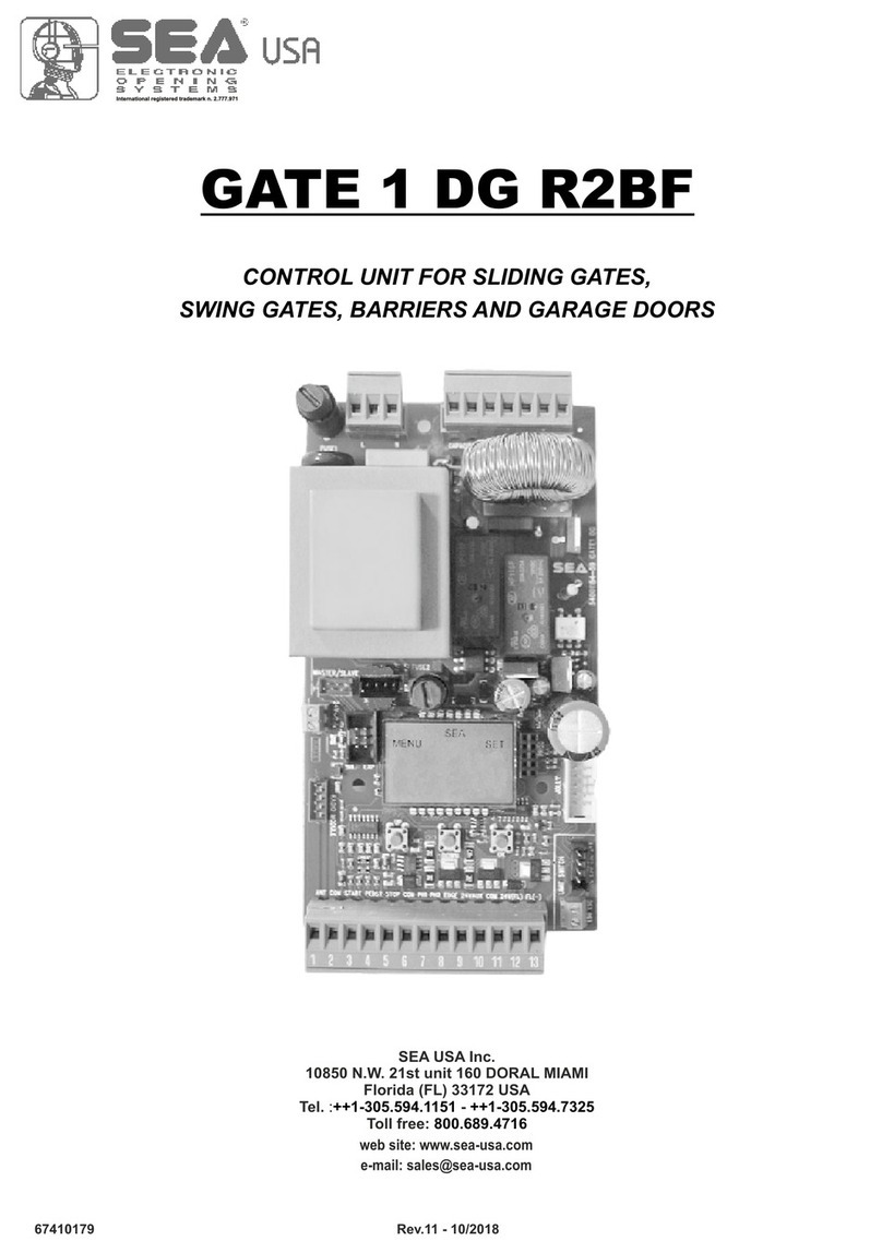
SEA
SEA GATE 1 DG R2BF User manual

SEA
SEA STAR 500 User manual
SEA
SEA FLIPPER Instruction manual

SEA
SEA LEPUS 600 User manual

