manuals.online logo
Brands
  1. Home
  2. •
  3. Brands
  4. •
  5. Sealey
  6. •
  7. Air Compressor
  8. •
  9. Sealey SA1015/3 User manual

Sealey SA1015/3 User manual

INSTRUCTIONS FOR:
BELT DRIVEN COMPRESSORS
Models: SA1015/3 & SA1020/3
Thank you for purchasing a Sealey product. Manufactured to a high standard this product will, if used according to these instructions
and properly maintained, give you years of trouble free performance.
SA1015/3 & SA1020/3 - 1069 - (2) - 050601
1. SAFETY INSTRUCTIONS
IMPORTANT: PLEASE READ THESE INSTRUCTIONS CAREFULLY. NOTE THE SAFE OPERATIONAL REQUIREMENTS, WARNINGS AND CAUTIONS.
USE THE PRODUCT CORRECTLY AND WITH CARE FOR THE PURPOSE FOR WHICH IT IS INTENDED. FAILURE TO DO SO MAY CAUSE
DAMAGE AND/OR PERSONAL INJURY AND WILL INVALIDATE THE WARRANTY. PLEASE KEEP INSTRUCTIONS SAFE FOR FUTURE USE.
1.1. ELECTRICAL SAFETY. p WARNING! It is the users responsibility to read, understand and comply with the following:
You must check all electrical equipment and appliances to ensure they are safe before using. You must inspect power supply leads, plugs and
all electrical connections for wear or damage. You must ensure the risk of electric shock is minimised by the installation of appropriate safety
devices. An RCCB (Residual Current Circuit Breaker) should be incorporated in the main distribution board. We also recommend that an RCD
(Residual Current Device) is used with all electrical products. It is particularly important to use an RCD with portable products that are plugged
into an electrical supply not protected by an RCCB. If in doubt consult a qualified electrician. You may obtain a Residual Current Device by
contacting your Sealey dealer. You must also read and understand the following instructions concerning electrical safety.
1.1.1. The Electricity At Work Act 1989 requires all portable electrical appliances, if used on business premises, to be tested by
a qualified electrician, using a Portable Appliance Tester (PAT), at least once a year.
1.1.2. The Health & Safety at Work Act 1974 makes owners of electrical appliances responsible for the safe condition of those appliances
and the safety of appliance operators. If in any doubt about electrical safety, contact a qualified electrician.
1.1.3. Ensure the insulation on all cables and the product itself is safe before connecting to the mains power supply.
See 1.1.1. & 1.1.2. above and use a Portable Appliance Tester (PAT).
1.1.4. Ensure that cables are always protected against short circuit and overload.
1.1.5. Regularly inspect power supply leads and plugs for wear or damage and connections to ensure that none is loose.
1.1.6. Important: Ensure the voltage marked on the product is the same as the power supply to be used, and check that the plug is fitted with the
correct capacity fuse.
1.1.7. DO NOT pull or carry the appliance by its power supply lead.
1.1.8. DO NOT pull plug from socket by the power cable.
1.1.9. DO NOT use worn or damage leads, plugs or connections. Immediately replace or have repaired by a qualified electrician.
1.1.10. NOTE: THIS PRODUCT IS INTENDED FOR USE ON AN INDUSTRIAL 30AMP SUPPLYWHICH MUST BE INSTALLED BY A QUALIFIED
ELECTRICIAN. It may be possible to operate the compressor on a Domestic 13 amp outlet under the following conditions: The mains supply
must conform to IEE Wiring Regulations, and the spur used to run the compressor must not include any other socket which could be used for
another appliance. The distance of the socket from the mains distribution point must not exceed 5 metres.
An extension lead must not be used.
1.1.11. Note: Under certain conditions the compressor will draw more than 13 amps. Consequently,
we recommend a 30 amp supply and suggest that a direct round pin plug/socket is installed by
a qualified electrician. In the event that you choose to use a domestic 13 amp supply,
we provide the plug wiring instructions as follows:
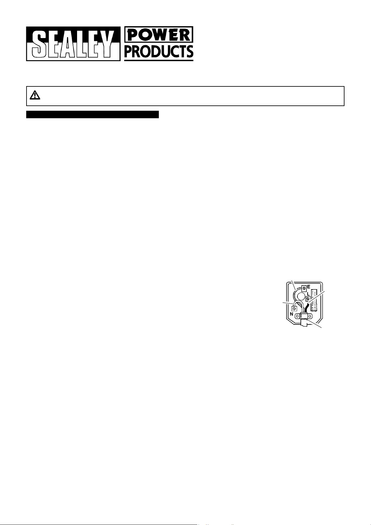
(UK only - see diagram at right). Ensure the unit is correctly earthed via a three-pin plug.
a) Connect the green/yellow earth wire to the earth terminal E.
b) Connect the brown live wire to the live terminal L.
c) Connect the blue neutral wire to the neutral terminal N.
d) Ensure the plug is fitted with a 13 amp fuse.
e) After wiring, check that there are no bare wires, that all wires have been correctly
connected, that the cable outer insulation extends past the cable restraint and that the restraint is tight.
NOTE: IF THE FUSE BLOWS REPEATEDLY WHEN USED ON A DOMESTIC 13 AMP SUPPLY, CONTACT A QUALIFIED
ELECTRICIAN TO INSTALL A 30 AMP SUPPLY.
Blue
Neutral
Wire
Yellow & Green
Earth Wire
Cable
Restraint
Brown
Live
Wire
1.2. GENERAL SAFETY INSTRUCTIONS
3Familiarise yourself with the application and limitations of the compressor.
3Ensure the compressor is in good order and condition before use. If in any doubt do not use the unit and contact an electrician/service agent.
pWARNING! Compressor must only be serviced by an authorised agent. DO NOT tamper with, or attempt to adjust, pressure switch or safety valve.
3Before moving or maintaining the compressor ensure that it is unplugged from the mains supply and that the tank pressure has been vented.
3Only use recommended attachments and parts. To use non-recommended items may be dangerous and will invalidate your warranty.
3Read the instructions regarding any accessory used with the compressor. Ensure the safe working pressure of any air appliance used exceeds the
compressor output pressure. If using a spray gun, check that the area selected for spraying is provided with air change system/ventilation.
3Ensure the air supply valve is turned off before disconnecting the air supply hose.
3Use the compressor in a well ventilated area and ensure it is placed on a firm surface.
3Keep tools and other items away from the compressor when it is in use and keep area clean and clear of unnecessary items.
3Ensure the air hose is not tangled, twisted or pinched.
3Keep children and unauthorised persons away from the work area.
7DO NOT dis-assemble compressor for any reason. The unit must be checked by qualified personnel only.
7DO NOT use the compressor outdoors, or in damp, or wet, locations and DO NOT operate within the vicinity of flammable liquids, gases or solids.
7DO NOT touch compressor cylinder, cylinder head or pipe from head to tank as these may be hot and will remain so for some time after shutdown.
7DO NOT attempt to move the compressor by pulling the air tool hose.
7DO NOT use the compressor for a task for which it is not designed.
7DO NOT deface the certification plate attached to the end of the compressor tank.
3.1. Remove compressor from packaging and inspect. If anything is found to be missing or damaged contact your supplier.
3.2. Save the packing material for future transportation of the compressor. We recommend that you store the packing
in a safe location, at least for the period of the guarantee. Then, if necessary, it will be easier to send the
compressor to the service centre.
3.3. Confirm that the voltage shown on compressor data plate corresponds with the supply voltage.
3.4. The compressor should be operated on a flat surface, or one that does not exceed 15Oeither transversely
or longitudinally (fig.2), and should be in a position that allows good air circulation around the unit.
3.5. Confirm that the air filter (fig.1.A) is fitted to the inlet port of the cylinder head and that the breather (fig.1.B)
is fitted to oil filler port.
3.6. Confirm that the oil level is at the maximum mark on the sight glass (fig.3).
2. INTRODUCTION & SPECIFICATIONS
The SA1015/3 and SA1020/3 Compressors have twin cylinder pumps belt driven by 230V 1ph motors and are capable of supplying air at up to
10 bar. In addition to pneumatic tools, the compressors are suitable for running accessories for blowing, washing, spraying and tyre inflation.
SA1015/3 & SA1020/3 - 1069 - (2) - 050601
3. PREPARATION
Free Air Delivery
(cfm)
Model
Max
Motor
Output
(hp)
Voltage/
Phase
Current
(A)
Pump
Type
Pump
Speed
(rpm)
Piston
Displacement
(cfm) At
2.5 Bar*
Max. At
6.0 Bar*
Tank
Capacity
(l)
Max.
Pressure
(psi/bar)
Noise
Level
(dB.A)
SA1015/3
SA1020/3
3
3
230/1
230/1
13
13
K9
K9
1800
1800
14
14
10.2
10.2
10.6
10.6
9.9
9.9
150
200
145/10
145/10
79
79
2.1. Specifications
2.2. Weights & Dimensions
fig. 3
fig. 1
Model Weight
(kg)
Dimensions
Length x Width x Height (mm)
SA1015/3
SA1020/3
79
91
1280 x 420 x 830
1420 x 420 x 1000
fig. 2
All performance figures are ± 5%
7DO NOT cover the compressor or restrict air flow around the machine whilst operating.
sDANGER! DO NOT direct the air hose towards people or animals.
7DO NOT operate the compressor without an inlet air filter (see fig.1.A).
7DO NOT allow anyone to operate the compressor unless they have received full instructions.
p WARNING! The air tank is a pressure vessel and the following safety measures apply:
DO NOT tamper with the safety valve, DO NOT modify or alter the tank in any way and DO NOT strap anything to the tank.
DO NOT subject the tank to impact, vibration or to heat and DO NOT allow contact with abrasives or corrosives.
DO drain condensation from tank daily, inspect inside walls for corrosion every three months and have a detailed tank inspection
carried out annually.
The tank shell must not fall below the certified thickness at any point.
p WARNING! If an electrical fuse blows, ensure it is replaced with an identical fuse type and rating (See para. 1.1.11).
3When not in use, store the compressor in a safe, dry, childproof location.
* Note: 2.5 bar is recommended pressure setting for spraying.
6.0 bar is recommended pressure setting for air tools.
A
B
C
p IMPORTANT
a. The motor on this compressor is 3HP/230V and at normal mains voltage will start within the capacity of a 13 amp fused circuit.
Certain local conditions relating to electrical supply in the UK can result in the voltage varying between a low of 216 volts and a
high of 253 volts. At such times of fluctuating voltage the 13 amp fuse in the compressor plug may blow. This is normal and
is not a fault with the compressor. However if it happens regularly we recommend that you consult an electrician with a view
to installing a 30 amp supply, with contact breaker, to avoid the inconvenience of frequent fuse replacement.
WARNING! An extension lead MUST NOT be used to connect compressor to the mains as the resulting voltage drop would
reduce motor output and pump performance, causing the 13 amp fuse to blow.
b. Take care when selecting tools for use with the compressor. Air tool manufacturers normally express the volume of air
required to operate a tool in cubic feet per minute (cfm). This refers to free air delivered by the compressor (air out) which
varies according to the pressure. Do not confuse this with the compressor displacement which is the air taken in by the
compressor (air in). Air out is always less than air in - due to losses within the compressor - and so it is important that,
before choosing equipment, you study the Free Air Delivery figures shown in the Specification chart, Section 2.
p WARNING! Ensure that you read, understand and apply Section 1 safety instructions.
4.1. Make sure the main switch (fig.4.1) is in position "O (Off).
4.2. Plug the lead into mains supply and start the compressor by turning the main switch to I (On).
4.3. When starting the compressor for the first time, leave it running with air outlet (fig.1.C) closed.
Make sure that the pressure in the tank rises and that the compressor stops automatically when the
max. pressure value allowed - written on the plate and shown on the gauge (fig.4.2) - is achieved.
The compressor will now operate automatically. The pressure switch stops the motor when the
maximum tank pressure is reached and restarts it when pressure falls below the minimum
threshold - approx. 2 bar (29psi) less than the maximum pressure.
4.4. Stop the compressor by turning the main switch (fig.4.1) off. The compressed air inside the compressor
head will flow out, making the restart easier and preventing the motor from being damaged.
DO NOT, other than in an emergency,stop the compressor by switching off the mains socket, or by
pulling the plug out, as the pressure relief will not then occur and motor damage may result upon restart.
When the compressor runs correctly and is stopped correctly there will be:
(a) a whistle of compressed air when the motor stops,
(b) a protracted whistle (about 20-25 seconds) when the compressor starts with no pressure in the tank.
4.5. The compressor is equipped with an overload cut-out to protect the motor. The manual reset (fig.5.D) should
not be operated until 3 minutes after cut-out, to allow the motor to cool. To restart, turn main switch off,
reset D and then turn main switch on. If, after restarting, the compressor again automatically cuts out turn
off at the main switch and contact Service Agent.
Note: a) If the motor does not cut in and out, but runs continuously when using an air appliance, the capacity
of the compressor may be too small for the equipment or tool.
b) The gauge (fig.4.2) indicates the pressure inside the main tank, NOT the pressure supplied to the air equipment. Should the
pressure in the tank exceed the pre-set switch (fig.4.6) maximum, a safety valve (fig.4.5) will activate.
p WARNING! For this reason DO NOT tamper with or adjust the switch or safety valve.
4. OPERATION
In order to keep the compressor in good working condition, periodic maintenance is essential.
pIMPORTANT! Failure to carry out maintenance tasks may invalidate the warranty on your compressor.
pWARNING! Before performing any maintenance operation, switch off compressor, disconnect from power supply and vent air from tank.
5.1. After the first 50 working hours. Operations to be carried out:
a) Check that all bolts/nuts are tight, particularly those retaining the crank case and cylinder head.
b) Replace the lubricating oil - see para 5.6.
5.2. Daily. Operation to be carried out :
a) Drain condensation by opening the valve C located under the tank.
5.3. Monthly (or more frequently, if the compressor operates in a very dusty atmosphere):
a) Check oil level and, if necessary, top up. b) Remove the air filter element and clean by blowing
through, with an air line at low pressure, from the clean side. Do not operate compressor without a filter
as foreign bodies or dust could damage the pump. c) Check belt tension. d) Check for oil leaks.
5.4. 3-Monthly. Operation to be carried out a) Check tank for internal corrosion.
5.5. Every 500 hours. Operations to be carried out :
a) Change air filter element.
b) Check the automatic cut-out at max. pressure and the automatic cut-in at 2 bar below.
5.6. Every 1000 hours. Operations to be carried out :
a) Replace the lubricating oil. For oil specifications see 5.8.
Remove the oil breather A and screw B, draining the oil into a container. Drain when the compressor
is hot so that oil drains rapidly and completely. Wash breather in kerosene, fuel oil or similar.
Replace screw B and refill through the filler aperture. Do not over-fill. Replace breather.
p WARNING! Never mix different oils and do not use non-detergent/low quality oils as compressor
may be damaged.
p WARNING! Dispose of waste oil only in accordance with local authority requirements.
5. MAINTENANCE
SA1015/3 & SA1020/3 - 1069 - (2) - 050601
fig. 4
fig. 5
A
B
C
01284 757500 01284 703534 E-mail: sales@sealey.co.uk
NOTE: It is our policy to continually improve products and as such we reserve the right to alter data, specifications and component parts without prior notice.
IMPORTANT: No liability is accepted for incorrect use of this equipment
WARRANTY: Guarantee is 12 months from purchase date, proof of which will be required for any claim.
INFORMATION: For a copy of our latest catalogue and promotions call us on 01284 757525 and leave your full name and address, including postcode.
Sole UK Distributor,
Sealey Group,
Bury St. Edmunds, Suffolk.
Declaration of Conformity We, the sole UK importer, declare that the products listed below are in conformity with the following
standards and directives.
The construction files for these products are held by the
Manufacturer and may be inspected, by a national authority,
upon request to Jack Sealey Ltd.
BELT DRIVEN COMPRESSORS
Models: SA1015/3 & SA1020/3
87/404/EEC Pressure Vessel Directive
89/336/EEC EMC Directive
73/23/EEC LV Directive
98/37/EC Machinery Directive
Signed by Mark Sweetman 6th June 2001
b) Check belt tension. A force of 3kg applied at the belt mid-point should give a deflection of approx. 10mm (fig.6). If adjustment is
required remember to maintain the alignment of the two pulleys (fig.6). Adjust by repositioning motor.
c) Check all tube fittings and electrical connections.
d) Inspect pressure tank inside and out for damage or corrosion.
5.7. Scheduled maintenance table
Maintenance
Operations Weekly 3 MonthlyMonthly 500 hrs. 1000 hrs.
Drain condensation 
Check oil level 
Clean intake filter 
Check belt tension 
Check condition of belt
and pulleys
Check tube fittings and
electrical connections
Replace oil
Internal & external
inspection of tank
General cleaning of
compressor
Replace air filter
Check tank for internal
corrosion
Check for oil leaks








SA1015/3 & SA1020/3 - 1069 - (2) - 050601
Fault Cause Remedy
Pressure drop in the tank Air leaks at connections
Run compressor to max. pressure, switch off.
Brush soap solution over connections and look for
bubbles. Tighten connections showing leaks.
If problem persists contact Authorised Service Agent.
Compressor noisy with metallic knock
Compressor speed fluctuates
Compressor does not reach max. pressure
Compressor does not stop at max. pressure
Compressor stops and does not restart
Pressure switch valve leaks when compressor is idle
Bearing or piston damage
Belt slipping
Filter clogged
Head gasket or valve fault
Pressure switch fault
Motor failure
Overload cut-out operated - motor overheating
Non-return valve seal defective
Contact Authorised Service Agent.
Adjust belt. See para. 5.6.b.
Replace filter element.
Contact Authorised Service Agent.
Press the button D to restart (fig.5).
Empty the air tank, remove the non-return valve cap
A (fig.7) and clean and, if necessary,
replace the seal B.
6. TROUBLE SHOOTING
5.8. Recommended oils
Recommended oil for compressors, suitable for room
temperatures ranging from +5OC to +25OC:
SEALEY CPO or equivalent SAE 40 compressor oil.
Room temperatures below +5OC:
SAE 20 compressor oil.
Approximate oil capacity: 0.45 litres.
For Jack Sealey Ltd. Sole UK importer of Sealey Power Products.
ALIGNMENT
fig. 6
A
B
fig. 7

This manual suits for next models

1

Other Sealey Air Compressor manuals

Sealey RE23RS User manual

Sealey

Sealey RE23RS User manual

Sealey sac5020e110v.v3 User manual

Sealey

Sealey sac5020e110v.v3 User manual

Sealey SAC1903B User manual

Sealey

Sealey SAC1903B User manual

Sealey SAC1103B User manual

Sealey

Sealey SAC1103B User manual

Sealey SACV52775B User manual

Sealey

Sealey SACV52775B User manual

Sealey Power PRODUCTS SA1565 User manual

Sealey

Sealey Power PRODUCTS SA1565 User manual

Sealey SAC0610E.V2 User manual

Sealey

Sealey SAC0610E.V2 User manual

Sealey SA3015/55 User manual

Sealey

Sealey SA3015/55 User manual

Sealey SA2306 User manual

Sealey

Sealey SA2306 User manual

Sealey SAC55075B User manual

Sealey

Sealey SAC55075B User manual

Sealey RE225.V3 User manual

Sealey

Sealey RE225.V3 User manual

Sealey SAC0607S User manual

Sealey

Sealey SAC0607S User manual

Sealey MAC2300 User manual

Sealey

Sealey MAC2300 User manual

Sealey SA951015 User manual

Sealey

Sealey SA951015 User manual

Sealey RE227 User manual

Sealey

Sealey RE227 User manual

Sealey SAC106B User manual

Sealey

Sealey SAC106B User manual

Sealey Power PRODUCTS SAC1276B User manual

Sealey

Sealey Power PRODUCTS SAC1276B User manual

Sealey SAC03224 User manual

Sealey

Sealey SAC03224 User manual

Sealey SAC2103B.V2 User manual

Sealey

Sealey SAC2103B.V2 User manual

Sealey SAC1276B User manual

Sealey

Sealey SAC1276B User manual

Sealey SAC2420E.V2 User manual

Sealey

Sealey SAC2420E.V2 User manual

Sealey SAC1903B User manual

Sealey

Sealey SAC1903B User manual

Sealey SAC2420E110V.V2 User manual

Sealey

Sealey SAC2420E110V.V2 User manual

Sealey SA22503 User manual

Sealey

Sealey SA22503 User manual

Popular Air Compressor manuals by other brands

EINHELL TE-AC 230/24 operating instructions

EINHELL

EINHELL TE-AC 230/24 operating instructions

Danfoss Turbocor TT Series Service manual

Danfoss

Danfoss Turbocor TT Series Service manual

Vmac G300005 owner's manual

Vmac

Vmac G300005 owner's manual

Porter-Cable PXCMF220VW instruction manual

Porter-Cable

Porter-Cable PXCMF220VW instruction manual

Baldor BD Series user manual

Baldor

Baldor BD Series user manual

SMC Networks CRP10 Series Operation manual

SMC Networks

SMC Networks CRP10 Series Operation manual

Gardner Denver APEX15-18A Operating and service manual

Gardner Denver

Gardner Denver APEX15-18A Operating and service manual

Pattfield Ergo Tools PE-1024 Original instructions

Pattfield Ergo Tools

Pattfield Ergo Tools PE-1024 Original instructions

Doosan 7/73-10/53 Operation and maintenance manual

Doosan

Doosan 7/73-10/53 Operation and maintenance manual

Craftsman 75114 Operator's manual

Craftsman

Craftsman 75114 Operator's manual

Ulvac C10T instruction manual

Ulvac

Ulvac C10T instruction manual

Danfoss DSH Series instructions

Danfoss

Danfoss DSH Series instructions

Workzone PT15101201 user manual

Workzone

Workzone PT15101201 user manual

Gast JUN-AIR 120R-40B manual

Gast

Gast JUN-AIR 120R-40B manual

Hyundai HY 2550 user manual

Hyundai

Hyundai HY 2550 user manual

Ariel JGW Series Technical manual

Ariel

Ariel JGW Series Technical manual

Grizzly QUIET Series owner's manual

Grizzly

Grizzly QUIET Series owner's manual

DeWalt DXCMLA1682066 instruction manual

DeWalt

DeWalt DXCMLA1682066 instruction manual

manuals.online logo
manuals.online logoBrands
  • About & Mission
  • Contact us
  • Privacy Policy
  • Terms and Conditions

Copyright 2025 Manuals.Online. All Rights Reserved.