manuals.online logo
Brands
  1. Home
  2. •
  3. Brands
  4. •
  5. Sealey
  6. •
  7. Air Compressor
  8. •
  9. Sealey SAC1903B User manual

Sealey SAC1903B User manual

INSTRUCTIONS FOR:
DIRECT DRIVE COMPRESSOR
(90LTR/3.0HP)
MODEL No: SAC1903B
Thank you for purchasing a Sealey product. Manufactured to a high standard this product will, if used according to these instructions and properly
maintained, give you years of trouble free performance.
1. SAFETY INSTRUCTIONS
IMPORTANT: PLEASE READ THESE INSTRUCTIONS CAREFULLY. NOTE THE SAFE OPERATIONAL REQUIREMENTS, WARNINGS & CAUTIONS. USE
THE PRODUCT CORRECTLY AND WITH CARE FOR THE PURPOSE FOR WHICH IT IS INTENDED. FAILURE TO DO SO MAY CAUSE DAMAGE OR
PERSONAL INJURY AND WILL INVALIDATE THE WARRANTY. PLEASE KEEP INSTRUCTIONS SAFE FOR FUTURE USE.
Original Language Version SAC1903B Issue: 1 - 21/02/11
all wires have been
correctly connected,
that the cable outer
insulation extends
beyond the cable
restraint and that the
restraint is tight.
Double insulated
products, which are
always marked with
this symbol , are
fitted with live (brown)
and neutral (blue) wires
only. To rewire, connect
the wires as indicated in
diagram. DO NOT connect either wire to the earth terminal.
1.1.10. Products which require more than 13 amps are supplied without
a plug. In this case you must contact a qualified electrician to
ensure that a suitably rated supply is available. We recommend
that you discuss the installation of an industrial round pin plug
and socket with your electrician.
 IMPORTANT! The use of extension leads to connect this
compressor to the mains is not recommended as the resulting
voltage drop reduces motor, and therefore pump performance.
1.1. ELECTRICAL SAFETY
WARNING! It is the responsibility of the owner and the operator to
read, understand and comply with the following: You must check all
electrical products, before use, to ensure that they are safe. You must
inspect power cables, plugs, sockets and any other connectors for wear
or damage. You must ensure that the risk of electric shock is minimised
by the installation of appropriate safety devices. A Residual Current
Circuit Breaker (RCCB) should be incorporated in the main distribution
board. We also recommend that a Residual Current Device (RCD) is
used. It is particularly important to use an RCD with portable products
that are plugged into a supply which is not protected by an RCCB. If in
any doubt consult a qualified electrician. You may obtain a Residual
Current Device by contacting your Sealey dealer. You must also read
and understand the following instructions concerning electrical safety.
1.1.1. The Electricity at Work Act 1989 requires that all portable
electrical appliances, if used on business premises, are tested
by a qualified electrician, using a Portable Appliance Tester
(PAT), at least once a year.
1.1.2. The Health & Safety at Work Act 1974 makes owners of
electrical appliances responsible for the safe condition of those
appliances and the safety of the appliance operators. If in any
doubt about electrical safety, contact a qualified electrician.
1.1.3. Ensure that the insulation on all cables and on the appliance is
safe before connecting it to the power supply. See 1.1.1. and
1.1.2. and use a Portable Appliance Tester.
1.1.4. Ensure that cables are always protected against short circuit
and overload.
1.1.5. Regularly inspect power supply cables and plugs for wear or
damage and check all connections to ensure that none is loose.
1.1.6. Important: Ensure that the voltage marked on the appliance
matches the power supply to be used and that the plug is fitted
with the correct fuse - see fuse rating at right.
1.1.7. DO NOT pull or carry the appliance by the power cable.
1.1.8. DO NOT pull the plug from the socket by the cable.
1.1.9. DO NOT use worn or damaged cables, plugs or connectors.
Immediately have any faulty item repaired or replaced by a
qualified electrician. When a BS 1363/A UK 3 pin plug is
damaged, cut the cable just above the plug and dispose of the
plug safely.
Fit a new plug according to the following instructions (UK only).
a) Connect the GREEN/YELLOW earth wire to the earth
terminal ‘E’.
b) Connect the BROWN live wire to the live terminal ‘L’.
c) Connect the BLUE neutral wire to the neutral terminal ‘N’.
d) After wiring, check that there are no bare wires, that
FUSE RATING 13 AMP
Blue
Neutral
Wire
Yellow & Green
Earth Wire
Cable
Restraint
Brown
Live
Wire
SA1903B KEY:
1. Compressor Unit
2. Motor thermal reset button
3. Electric motor
4. Pressure reducer
5. Compressed air outlet
6. Output pressure gauge
7. Tank pressure gauge
8. Tank
9. Wheel
10. Condensate drain valve
11. Pressure switch
12. Check valve
13. Belt guard
fig.1
1.2. GENERAL SAFETY
3 Familiarise yourself with the application and limitations of the
compressor.
3 Ensure the compressor is in good order and condition before
use. If in any doubt do not use the unit and contact an
electrician/service agent.
WARNING! Compressor must only be serviced by an
authorised agent. DO NOT tamper with, or attempt to
adjust, pressure switch or safety valve.
3 Before moving, or maintaining the compressor ensure it is
unplugged from the mains supply and that the air tank
pressure has been vented.
3 Maintain the compressor in good condition and replace any
damaged or worn parts. Use genuine parts only. Unauthorised
parts may be dangerous and will invalidate your warranty.
3 Read the instructions relating to any accessory to be used
with this compressor. Ensure the safe working pressure of any
air appliance used exceeds compressors output pressure. If
using a spray gun, check that the area selected for spraying is
provided with an air change system/ventilation.
3 Ensure the air supply valve is turned off before disconnecting
the air supply hose.
3 To move the compressor use the handle only. Bear in mind
that the compressor has a high centre of gravity. DO NOT
attempt to lift or move the compressor by any other means.
3 Use the compressor in a well ventilated area and ensure it is
placed on a firm surface.
3 Keep tools and other items away from the compressor when
it is in use, and keep area clean and clear of unnecessary
items.
3 Ensure the air hose is not tangled, twisted or pinched.
3 Keep children and unauthorised persons away from the
working area.
7 DO NOT dis-assemble compressor for any reason. The unit
must be checked by qualified personnel only.
7 DO NOT use the compressor outdoors, or in damp, or wet,
locations.
7DO NOT operate within the vicinity of flammable liquids, gases
or solids.
7 DO NOT touch compressor cylinder, cylinder head or pipe
from head to tank as these may be hot and will remain so for
some time after shutdown.
7 DO NOT use this product to perform a task for which it has not
been designed.
7 DO NOT deface the certification plate attached to the
compressor tank.
7 DO NOT cover the compressor or restrict air flow around the
unit whilst operating.
q DANGER! DO NOT direct the output jet of air towards
people or animals.
7DO NOT operate the compressor without an air filter.
7DO NOT allow anyone to operate the compressor unless
they have received full instructions.
 WARNING! The air tank is a pressure vessel and the
following safety measures apply:
7DO NOT tamper with the safety valve, DO NOT modify or alter
the tank in any way and DO NOT strap anything to the tank.
7DO NOT subject the tank to impact, vibration or to heat and
DO NOT allow contact with abrasives or corrosives.
3Drain condensation from tank daily and inspect both inside
and outside walls for corrosion as stated in the maintenance
schedule in section 5. The tank shell must not fall below the
certified thickness at any point.
 WARNING! If an electrical fuse blows, ensure it is replaced
with an identical fuse type and rating.
3When not in use, store the compressor carefully in a safe,
dry, childproof location.
Original Language Version SAC1903B Issue: 1 - 21/02/11
2. INTRODUCTION & SPECIFICATIONS
Suitable for the professional workshop, this compressor is fitted with
a genuine 3hp motor. Twin capacitors and a centrifugal switch aid
trouble free start on a 13amp supply. Pump features a heavy duty full
cast cylinder capped by an alloy head for improved heat dissipation
and long life. Heavy-duty drive guard protects belt and flywheel that
is designed to force air over the pump to aid cooling. Supplied with
full CE certification, test certificates and
operation / maintenance manual.
2.1. SPECIFICATION
Model:...............................................................................SAC1903B
Motor Output (HP):............................................................................3
Voltage / Phase: .........................................................................230/1
Input current: .................................................................................13A
Speed (rpm): ...............................................................................1636
Air Displacement (cfm/Lm):...................................................13.4/380
Max Free Air Delivery (cfm/Lm):..............................................9.2/275
Max Pressure (psi/bar):............................................................145/10
Tank Capacity (L): ...........................................................................90
Dimensions (WxDxH) (mm):.........................................525x495x1130
Weight (kg): .....................................................................................65
Noise (dB.A): ...................................................................................74
Noise LwA (dB.A): ...........................................................................96
3. PREPARATION
3.1. Remove compressor from packaging and inspect for any
shortages or damage. If anything is found to be missing or
damaged contact your supplier.
3.2. Save the packing material for future transportation of the
compressor. We recommend that you store the packing in a
safe location, at least for the period of the guarantee. Then, if
necessary, it will be easier to send the compressor to the
service centre.
3.3. Confirm that the mains voltage corresponds with the voltage
shown on the compressor data plate.
3.4. As this compressor has a higher centre of gravity
compared to horizontally orientated models it should only
be used on a sound and level surface. Take great
care when moving the compressor and do not leave it on an
incline during transit. Site in a well ventilated area, protected
against atmospheric pollution and not in a place subject to
explosion hazard. Check if the compressor moves whilst in
operation – if it does, secure the wheels with two wedges. If
the surface is in a raised position, make sure it cannot fall,
securing it in a suitable way.
3.5. To ensure good ventilation and efcient cooling, the
compressor’s belt guard must be at least 100cm from any wall.
3.6. Take care to transport the compressor correctly, do not over
turn it or lift it with hooks or ropes.
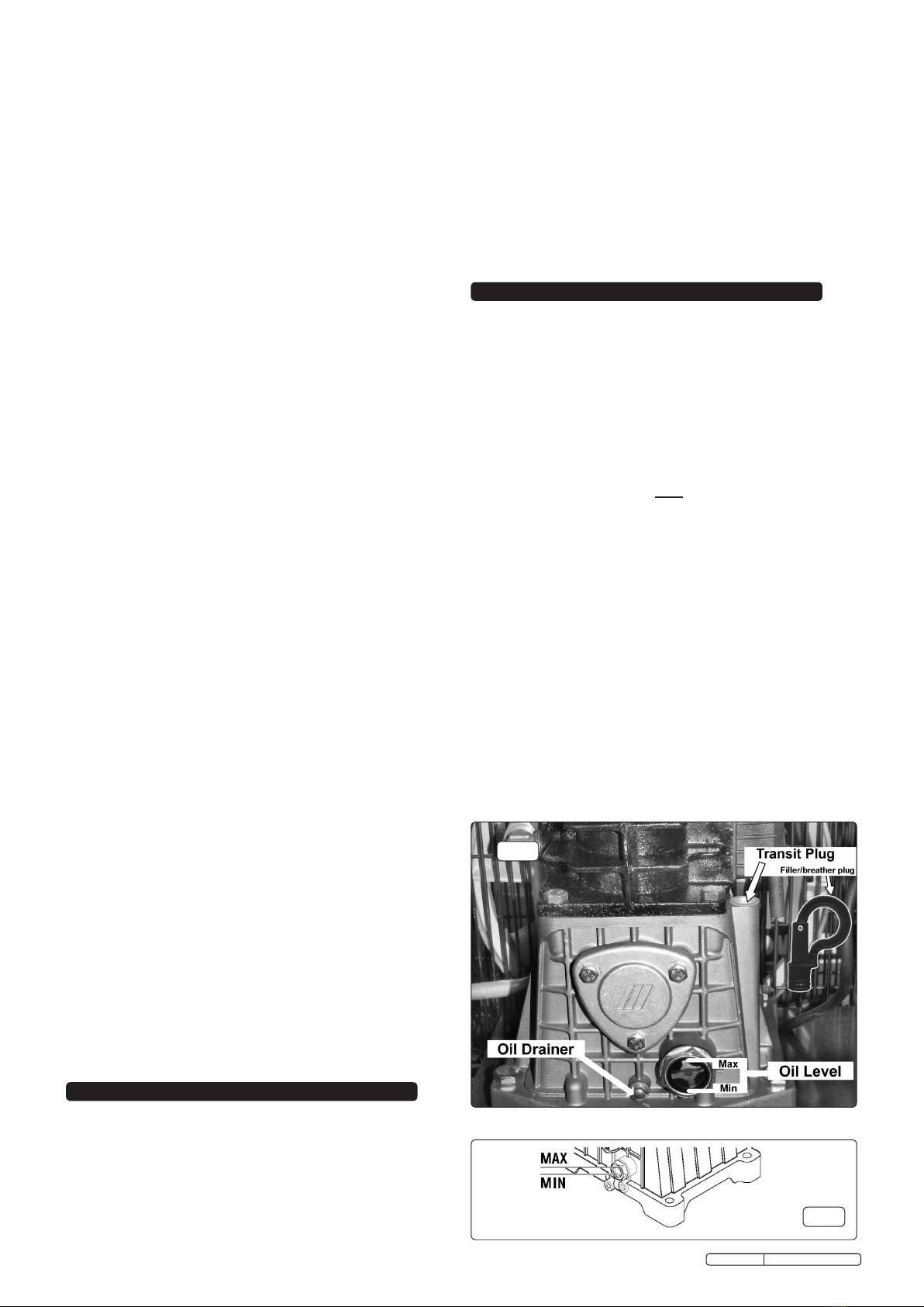
3.7. Remove the plastic transit plug from the oil filler hole (fig.2)
and replace it with the filler/breather plug. It is a push fit,
ensure that it is pushed fully home.
3.8. Before using the compressor, check the oil level by observing
the sight glass as shown in fig.3. If the oil is not up to the max
mark it should be topped up with synthetic oil suitable for
temperatures ranging from -5°C to 45°C (viscosity 5W50). We
do not recommend using mineral oil in these compressors. Do
not overfill.
fig.2
fig.3
5. MAINTENANCE
In order to keep the compressor in good working condition,
periodic maintenance is essential.
IMPORTANT! Failure to carry out maintenance tasks may
invalidate the warranty on your compressor.
WARNING! Before performing any maintenance operation,
switch off the compressor, disconnect from electricity
supply and release all air from the tank (except for 5.3.a)
5.1. Operations to be carried out after the first 50 working hours:
a) Check that all bolts/nuts are tight, particularly those
retaining the crankcase and cylinder head.
b) Replace the lubricating oil - see para 5.5.
5.2. Operations to be carried out weekly:
a) Drain condensation by opening the valve located under the
tank (fig.6). Place a container under the valve and open the
valve by turning anti-clockwise.
WARNING! Take care if there is still pressure inside the cylinder
as water could flow out with considerable force.
Recommended pressure 1 - 2bar max.
b) Check oil level and, if necessary, top up.
5.3. Operations to be carried out every 50 hours
(or more frequently, if the compressor operates in a very
dusty atmosphere):
a) Remove the air filter element (fig.5). Using stored air from
the compressor's tank, clean the filter with compressed air.
(Wear eye protection and DO NOT direct air towards the
body or hands). DO NOT operate the compressor without
the filter as foreign bodies or dust could seriously damage
the pump. Replace the filter element and air filter housing.
b) Check for oil leaks.
5.4. Operations to be carried out every 100 hours:
a) Check the automatic cut-out at max. pressure and the
automatic cut-in at 2bar below.
5.5. Operations to be carried out every 400 hours:
a) Replace the lubricating oil. For oil specifications see 5.6.
Remove the filler/breather plug (see fig.2 ) then remove oil
drain plug, draining the oil into a container. Drain when the
compressor is hot so that the oil drains rapidly and
completely. Incline compressor to ensure complete
drainage. Replace oil drain plug and refill through the filler/
breather aperture. Do not overfill. Replace plug.
4. OPERATION
WARNING! Ensure that you have read, understood and
apply Section 1 safety instructions.
IMPORTANT! The use of extension leads to connect this
compressor to the mains is not recommended as the
resulting voltage drop reduces motor, and therefore pump
performance, and could cause damage to the compressor.
NOTE: Take care when selecting tools for use with the
compressor. Air tool manufacturers normally express the
volume of air required to operate a tool in cubic feet per minute
(cfm). This refers to free air delivered by the compressor (‘air
out’) which varies according to the pressure setting. Do not
confuse this with the compressor displacement which is the air
taken in by the compressor (‘air in’). ‘Air out’ is always less than
‘air in’ due to losses within the compressor.
4.1. STARTING THE COMPRESSOR
To turn the compressor on, use the switch on the top of
the pressure switch housing (figs.4.1). Turn the switch clockwise
to position 'I' to start the compressor and anti-clockwise to
position 'O' to stop it.
4.2. Check that the ON/OFF switch is in the 'O' position. The
pressure regulator (fig.4.2) should be closed and the output
gauge (fig.4.4) must read Zero ‘0’ bar.
4.3. Plug into mains supply and start the compressor by turning the
switch to the 'I' position.
4.4. When starting the compressor for the first time, leave it running
with no air tools connected to the air outlet. Make sure that
pressure in the tank rises and that the compressor stops
automatically when the maximum pressure value allowed, written
on the plate and shown on the gauge (figs.4.5) is achieved. The
compressor will now operate automatically. The pressure switch
stops the motor when the maximum tank pressure is reached
and restarts it when the pressure falls below the minimum
threshold - approx. 2 bar (29psi) less than the maximum
pressure.
4.5. Stop the compressor by turning the main switch to the 'O'
position. The compressed air inside the compressor head will
flow out, making the restart easier and preventing the motor from
being damaged. DO NOT, other than in an emergency,stop the
compressor by switching off the mains socket, or by pulling the
plug out, as the pressure relief will not then operate and motor
damage may result upon restart.
4.6. The motor of the compressor is fitted with a thermal breaker
located in the housing on top of the motor. The manual resetting
button is located in the end of the housing as shown in fig.7A.
When the breaker is tripped, wait for a few minutes and then
press the reset button.
4.7. The output pressure is regulated by the pressure regulator
(fig.4.2). Turn the knob clockwise to increase pressure and anti-
clockwise to reduce it. Lock knob in position at required pressure
with locking ring. To determine the correct working pressure for
any piece of equipment check the corresponding manual. When
the compressor is not being used, set the regulated pressure to
zero so as to avoid damaging the pressure regulator.
NOTE: a) If the motor does not cut in and out, but runs
continuously when using an air appliance, the capacity of the
compressor may be too small for the equipment or tool.
b) The gauge (fig.4.5) indicates the pressure inside the main
tank, NOT the pressure supplied to the air equipment. Should
the pressure in the main tank exceed the pre-set switch
maximum, the safety valve will activate.
WARNING! For this reason DO NOT tamper with, or adjust,
the switch or safety valve.
Maintenance Operations Weekly 50hrs 100hrs 400 hrs
Drain condensation •
Check oil level •
Clean intake filter •
Check for oil leaks •
Replace oil •
Check cut-out •
General cleaning of
compressor •
Replace air filter •
Check tube fittings and
electrical connections •
Internal & external
inspection of tank •
Original Language Version SAC1903B Issue: 1 - 21/02/11
fig.4
WARNING! Never mix different oils and do not use non-
detergent/low quality oils as the compressor may be damaged.
WARNING! Dispose of waste oil only in accordance with
local authority requirements.
b) Replace air filter. (See fig.5).
c) Check all tube fittings and electrical connections.
d) Inspect pressure tank inside and out for damage or corrosion.
5.6. Recommended oils
Synthetic oil suitable for temperatures ranging from -5°C to 45°C:
viscosity 5W50. We do not recommend using mineral oil in these
compressors.
Part No. Qty. Description
FSO1 1ltr x 12 Compressor oil fully synthetic
FSO1S 1ltr x 1 Compressor oil fully synthetic
FSO5 5ltr x 1 Compressor oil fully synthetic
5.7. IMPORTANT WARNING - Air contaminants taken into the
compressor will affect optimum performance. Example: Body
 llerdustorpaintoverspraywillclogthepumpintakelterand 
may cause internal damage to pump/motor components. Please
note that any parts damaged by any type of contamination will
not be covered by warranty.
fig.6
6. TROUBLE SHOOTING
NOTE: It is our policy to continually improve products and as such we reserve the right to alter data, specifications and component parts without prior notice.
IMPORTANT: No liability is accepted for incorrect use of this product.
WARRANTY: Guarantee is 12 months from purchase date, proof of which will be required for any claim.
INFORMATION: For a copy of our latest catalogue and promotions call us on 01284 757525 and leave your full name and address, including postcode.
01284 757500
01284 703534
sales@sealey.co.uk
Sole UK Distributor, Sealey Group,
Kempson Way, Suffolk Business Park,
Bury St. Edmunds, Suffolk,
IP32 7AR
www.sealey.co.uk
Web
email
fig.5
fig.7 fig.8
Fault Cause Remedy
Pressure drop in the
tank.
Air leaks at
connections.
Run compressor to max.
pressure, switch off.
Brush soap solution over
connections and look for
bubbles. Tighten connections
showing leaks. If problem
persists contact Authorised
Service Agent.
Pressure switch
valve leaks when
compressor is idle.
Non-return valve seal
defective.
Discharge all tank pressure.
Referring to fig.8, unscrew
valve cap 'A'. Clean rubber
disc 'B' and its seat. Refit all
parts accurately.
Compressor stops
and does not restart.
Power failure.
Motor failure.
Check electricity supply and
fuse.
Contact Authorised Service
Agent.
Compressor does
not stop at max
pressure.
Pressure switch fault. Contact Authorised Service
Agent.
Compressor does
not reach max
pressure.
Filter clogged.
Head gasket or valve
fault.
Replace filter element.
Contact Authorised Service
Agent.
Compressor noisy
with metallic knock.
Low oil level.
Bearing or piston
damage.
Turn off and top up oil
immediately.
Contact Authorised Service
Agent.
Original Language Version SAC1903B Issue: 1 - 21/02/11
Parts support is available for this product. To obtain a parts listing and/or diagram, please log on to
www.sealey.co.uk, email sales@sealey.co.uk or phone 01284 757500.

Other Sealey Air Compressor manuals

Sealey SAC0607S User manual

Sealey

Sealey SAC0607S User manual

Sealey SA2110/3 User manual

Sealey

Sealey SA2110/3 User manual

Sealey SAC1903B User manual

Sealey

Sealey SAC1903B User manual

Sealey SAC5020E110V User manual

Sealey

Sealey SAC5020E110V User manual

Sealey MAC2300 User manual

Sealey

Sealey MAC2300 User manual

Sealey SA2010/3 User manual

Sealey

Sealey SA2010/3 User manual

Sealey SA22503 User manual

Sealey

Sealey SA22503 User manual

Sealey SAC2103B.V2 User manual

Sealey

Sealey SAC2103B.V2 User manual

Sealey SAC20030B User manual

Sealey

Sealey SAC20030B User manual

Sealey SAC2420E110V.V3 User manual

Sealey

Sealey SAC2420E110V.V3 User manual

Sealey MAC2300 User manual

Sealey

Sealey MAC2300 User manual

Sealey VS7011.V3 User manual

Sealey

Sealey VS7011.V3 User manual

Sealey MAC04D User manual

Sealey

Sealey MAC04D User manual

Sealey SAC2420E.V2 User manual

Sealey

Sealey SAC2420E.V2 User manual

Sealey SAC1103B User manual

Sealey

Sealey SAC1103B User manual

Sealey RE23RS User manual

Sealey

Sealey RE23RS User manual

Sealey MAC1250 User manual

Sealey

Sealey MAC1250 User manual

Sealey Power PRODUCTS SAC3103B User manual

Sealey

Sealey Power PRODUCTS SAC3103B User manual

Sealey SAC55075B User manual

Sealey

Sealey SAC55075B User manual

Sealey SAC4505555B User manual

Sealey

Sealey SAC4505555B User manual

Sealey VS1540 User manual

Sealey

Sealey VS1540 User manual

Sealey SAC5030VE.V3 User manual

Sealey

Sealey SAC5030VE.V3 User manual

Sealey SAC00015 User manual

Sealey

Sealey SAC00015 User manual

Sealey RE229 User manual

Sealey

Sealey RE229 User manual

Popular Air Compressor manuals by other brands

American Eagle SHD 30 owner's manual

American Eagle

American Eagle SHD 30 owner's manual

Vmac VR70 installation manual

Vmac

Vmac VR70 installation manual

California Air Tools 20015HP owner's manual

California Air Tools

California Air Tools 20015HP owner's manual

Danfoss CH290 Application guide

Danfoss

Danfoss CH290 Application guide

Oshkosh Corporation IMT CAS40P Installation, Operation, Maintenance & Parts Manual

Oshkosh Corporation

Oshkosh Corporation IMT CAS40P Installation, Operation, Maintenance & Parts Manual

Conrad 85 66 48 operating instructions

Conrad

Conrad 85 66 48 operating instructions

Mea SMARTPACK 100-H Owner's/operator's manual

Mea

Mea SMARTPACK 100-H Owner's/operator's manual

Quincy Compressor QGS 90 Instruction book

Quincy Compressor

Quincy Compressor QGS 90 Instruction book

BLACKMER LB942A Installation, operation and maintenance instructions

BLACKMER

BLACKMER LB942A Installation, operation and maintenance instructions

Kobalt 138336 parts manual

Kobalt

Kobalt 138336 parts manual

Emerson Copeland Scroll ZS KAE Series Application Engineering Bulletin

Emerson

Emerson Copeland Scroll ZS KAE Series Application Engineering Bulletin

Craftsman 919.165280 owner's manual

Craftsman

Craftsman 919.165280 owner's manual

Craftsman 919.727580 owner's manual

Craftsman

Craftsman 919.727580 owner's manual

Atlas Copco G 2 Instruction book

Atlas Copco

Atlas Copco G 2 Instruction book

Phoenix CAM owner's manual

Phoenix

Phoenix CAM owner's manual

Profile CR60 operating instructions

Profile

Profile CR60 operating instructions

Outbac OTB600 user manual

Outbac

Outbac OTB600 user manual

Ingersoll-Rand IRN37-160K-CC Operation and maintenance manual

Ingersoll-Rand

Ingersoll-Rand IRN37-160K-CC Operation and maintenance manual

manuals.online logo
manuals.online logoBrands
  • About & Mission
  • Contact us
  • Privacy Policy
  • Terms and Conditions

Copyright 2025 Manuals.Online. All Rights Reserved.