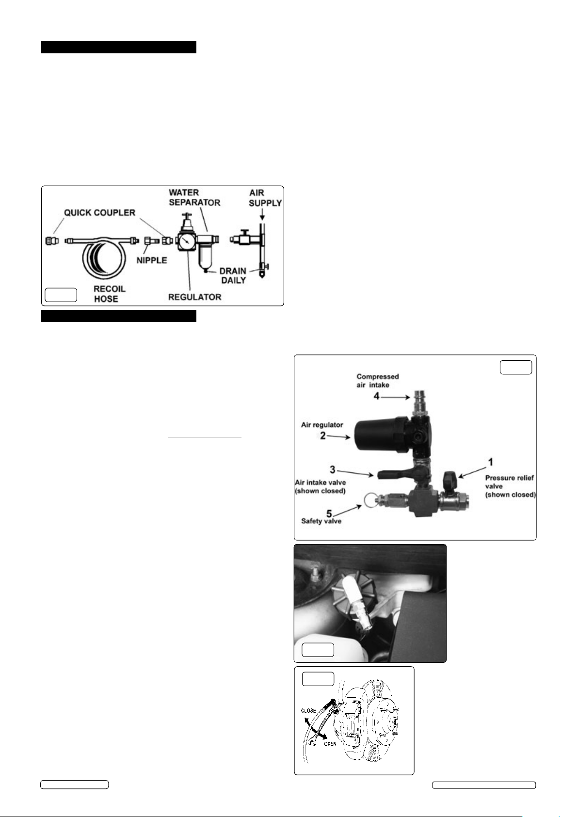
manuals.online logo
Brands
  1. Home
  2. •
  3. Brands
  4. •
  5. Sealey
  6. •
  7. Tools
  8. •
  9. Sealey VS0204A User manual

Sealey VS0204A User manual

Keep this product in good working order and condition, take immediate action to repair or replace damaged parts.
Use approved parts only. Unapproved parts may be dangerous and will invalidate the warranty.
Keep children and unauthorised persons away from the work area.
Keep work area clean and tidy and free from unrelated materials.
Ensure the work area has adequate lighting.
DO NOT use the kit to perform a task for which it is not designed.
DO NOT allow untrained persons to use the kit.
DO NOT use when tired or under the influence of drugs, alcohol or intoxicating medication.
After use, clean equipment and store in a cool, dry, childproof area.
Dispose of waste liquids in accordance with local authority regulations.
Always read and comply with the warnings on the brake fluid container.
Wear eye protection and keep skin contact to a minimum. If brake fluid enters eyes rinse with plenty of water and seek medical advice. If
swallowed seek medical advice immediately.
WARNING! Only use new Brake Fluid, used Brake Fluid or other fluids will contaminate the system and possible brake system failure may
result.
WARNING! DO NOT pollute the environment by allowing uncontrolled discharge of fluids.
WARNING! Brake fluid is flammable - keep away from sources of ignition, including hot surfaces e.g. exhaust manifold.
WARNING! Brake fluid will damage paintwork. Any spillage should be flushed with water immediately.
WARNING! DO NOT allow the fluid capacity in the unit to fall below ½ litre during the bleeding process otherwise air may enter
the system.
BRAKE & CLUTCH PNEUMATIC
PRESSURE BLEEDER
MODEL NO: VS0204A
One-man pressure brake and clutch bleeding system suitable for the professional workshop. Low pressure tank (20-40psi) can be
pre-charged with compressed air - making the unit fully portable. Large reservoir means reduced risk of running the system dry during
bleeding process or complete fluid change. Suitable for use on ABS systems. Features a long delivery hose for operation with a low level
ramp and long reach handle for easy mobility. Supplied with Ø45mm cap with 90° angled connector which is suitable for most European
models. For other applications order optional Brake Reservoir Cap 45mm Straight Connector - Model no. VS0204SA, Universal Adaptor -
Model no. VS820UA or Brake & Clutch Bleeder Cap Set - Model no. VS0204B.
Model No: .......................................VS0204A
Maximum Air Supply: . . . . . . . . . . . . . . . . . . . . . . . . . . . . . . . .20-40psi
Air consumption:.....................................4.5cfm
Inlet size: .........................................1/4”BSP
Tank capacity:......................................5.0 litres
Hose Length: ....................................... 3.7mtr
Weight: .............................................6.8kg
Fig.1
IMPORTANT: PLEASE READ THESE INSTRUCTIONS CAREFULLY. NOTETHE SAFEOPERATIONALREQUIREMENTS, WARNINGS& CAUTIONS. USE THE PRODUCT
CORRECTLY AND WITH CAREFOR THE PURPOSE FOR WHICH IT ISINTENDED. FAILURE TO DO SO MAY CAUSE DAMAGE AND/OR PERSONALINJURY AND WILL
INVALIDATETHE WARRANTY. KEEP THESE INSTRUCTIONS SAFEFOR FUTURE USE.
Thank you for purchasing a Sealey product. Manufactured to a high standard, this product will, if used according to these
instructions, and properly maintained, give you years of trouble free performance.
Refer to
instructions Wear eye
protection
1. SAFETY
2. INTRODUCTION
3. SPECIFICATION
VS0204A Issue:2 (2) - 18/09/18
Original Language Version
© Jack Sealey Limited
  Recommendedhookupisshowning.2.
4.1. Y o u willrequireanairpressureof40psiandairowaccording
  tospecication.
4.2. Ensure that the air supply is clean and does not exceed 40psi.
Too high a pressure and/or unclean air may damage the
diaphragm and will shorten the product life due to excessive
wear and may cause damage and/or personal injury.
4.3. Drain the air tank daily. Water in the air line will damage the
unit and invalidate your warranty.
4.4. Theminimumhosediametershouldbe¼"I.Dandttings
must have the same internal dimensions.
4.5. Keep hose away from heat, oil and sharp edges. Check
hoses for wear and make certain that all connections are secure.
5.1. Brake bleeding procedure.
Refer to the vehicle manufacturer’s instructions for brake
bleeding and wheel sequence before proceeding. If no
specific instructions from the vehicle manufacturer exist,
follow the instructions detailed below.
WARNING! Familiarise yourself with the hazards of brake
fluid - read manufacturer’s instructions on the container.
DO NOT touch the vehicle’s brake pedal whilst bleeding
the brakes.
5.1.1. Check that the pressure release valve (fig.3.1) is open and
that there is no pressure within the unit. Unscrew the filler
cap (fig.1.1) on the unit and top up to full capacity with new
brake fluid. Replace filler cap and close the pressure release
valve.
WARNING! DO NOT allow the fluid capacity within the
unit to fall below ½ litre during the bleeding process
otherwise air may enter the system.
NOTE: The diaphragm may be visible from the neck of the
filler and will require deflating before filling, this can be done
by pushing down on the diaphragm with a clean blunt
instrument.
5.1.2. Check that the air regulator (fig.3.2) is turned fully counter
clockwise, the air intake valve (fig.3.3) and the fluid supply
pipe valve (fig.1.3) are in the closed positions.
5.1.3. Connect the brake bleeder (fig.3.4) to a suitable compressed
air supply.
5.1.4. Slowly open the air intake valve (fig.3.3) and turn the air
regulator clockwise until a pressure of 20psi is registered on
the pressure gauge (fig1.2).
NOTE: The brake bleeder can be used remotely by closing
the air supply valve once the unit has been charged with air
and then disconnect the air supply.
DO NOT exceed the maximum pressure of 40psi, if the unit
exceeds this pressure the safety valve (fig.3.5) will be
activated.
5.1.5. Connect one of the adaptors to the end of the fluid supply
pipe and hold over a waste oil container, slowly open the
valve (fig.1.3) to release air from the supply pipe. When
brake fluid is free flowing, close the valve.
5.1.6. Remove the cap on the vehicle’s brake fluid reservoir. If the
brake fluid level is not at maximum, top it up and select a
suitable adaptor for the vehicle. In some cases a universal
adaptor will be required, see section 5.4. Tighten the adaptor
onto the master cylinder ensuring that a good seal is
achieved (fig.4).
5.1.7. Connect the fluid supply pipe quick connector to the adaptor
and slowly open the valve (fig.1.3) to pressurise the system.
5.1.8. Starting with the brake furthest away from the master
cylinder connect the tube from the bleeding bottle to the
nipple and using a brake spanner open the nipple
approximately ¼ turn (fig.5), brake fluid will flow through the
clear pipe into the bottle, when there are no visible bubbles
tighten the bleed nipple.
5.1.9. Repeat the process at each wheel in turn as necessary.
5.1.10. To remove the brake bleeder, shut off the fluid supply pipe
valve (fig.1.3), close the air intake valve (fig.3.3) and open
the pressure release valve to depressurise the unit.
5.1.11. Disconnect the fluid supply pipe from the adaptor, taking care
not to spill any brake fluid and remove the adaptor from the
brake fluid reservoir. Any excess fluid in the reservoir should
be removed using the supplied rubber squeeze and disposed
of into a suitable waste oil container.
5.1.12. Refit the original brake fluid reservoir cap.
5.2. Changing the brake fluid.
5.2.1. Carry out the brake bleeding procedure as described above.
5.2.2. When new fluid can be seen in the clear tube tighten the
brake nipple.
5.2.3. Repeat this procedure at each wheel in turn.
5.2.4. Disconnect as above (4.1.10 & 4.1.11).
NOTE: When brake bleeding and/or fluid changing is
complete, test the action of the brake pedal to ensure that the
brakes are working and are not spongy before using the
vehicle on the road.
5.3. Clutch bleeding procedure.
Refer to the relevant vehicle manufacturer’s instructions for
clutch bleeding procedure. If no specific instructions from the
vehicle manufacturer exist, the same procedures as for brake
bleeding should be followed.
Fig.2
Fig.3
Fig.4
Fig.5
4. AIR SUPPLY
5. OPERATION
VS0204A Issue:2 (2) - 18/09/18
Original Language Version
© Jack Sealey Limited
6.1. Ensurethattheunitisdepressurisedbeforecarryingoutanymaintenanceanddrainalluidsfromthemaintankandfromtheuid
supply tube.
6.2. Cleanupanyspilledbrakeuidandwipedownwithacleancloth.
6.3. Store in a clean, dry and childproof location.
5.4. Universal adaptors Model no. VS820UA
5.4.1. Universal adapters can be fitted to brake or clutch master cylinder fluid reservoirs using the universal adapter clamps, the two hook
bolts and chains. Wrap the chain around the brake or clutch master cylinder and locate through the two holes in the adaptor and the
two slots in the clamp, take out the slack in the chain using the nuts and then tighten the clamp to seal the adaptor to the master
cylinder (fig.6).
5.5. Brake & Clutch Bleeder Cap Set Model no. VS0204B Fig.7
Comprehensive set of brake and clutch reservoir bleed caps, supplied as standard with Model no. VS0204 and VS0207. Also
compatible with Model no's VS820, VS821, VS0204A, offering a greater coverage of European, Japanese and US manufacturers.
Fig.6 Fig.7
6. MAINTENANCE
VS0204A Issue:2 (2) - 18/09/18
Original Language Version
© Jack Sealey Limited
Sealey Group, Kempson Way, Suffolk Business Park, Bury St Edmunds, Suffolk. IP32 7AR
01284 757500 01284 703534 sales@sealey.co.uk www.sealey.co.uk
Note: It is our policy to continually improve products and as such we reserve the right to alter data, specifications and component parts without
prior notice.
Important: No Liability is accepted for incorrect use of this product.
Warranty: Guarantee is 12 months from purchase date, proof of which is required for any claim.
ENVIRONMENT PROTECTION
Recycle unwanted materials instead of disposing of them as waste. All tools, accessories and packaging should be sorted, taken to
a recycling centre and disposed of in a manner which is compatible with the environment. When the product becomes completely
unserviceable and requires disposal, drain any fluids (if applicable) into approved containers and dispose of the product and fluids
according to local regulations.

Other Sealey Tools manuals

Sealey AK9624EV User manual

Sealey

Sealey AK9624EV User manual

Sealey hp1000.V2 User manual

Sealey

Sealey hp1000.V2 User manual

Sealey FG001 User manual

Sealey

Sealey FG001 User manual

Sealey AK3988 User manual

Sealey

Sealey AK3988 User manual

Sealey SCR02B User manual

Sealey

Sealey SCR02B User manual

Sealey VSE5312.V2 User manual

Sealey

Sealey VSE5312.V2 User manual

Sealey VS701 User manual

Sealey

Sealey VS701 User manual

Sealey VSE135.V3 User manual

Sealey

Sealey VSE135.V3 User manual

Sealey VS911.V2 User manual

Sealey

Sealey VS911.V2 User manual

Sealey RS13 User manual

Sealey

Sealey RS13 User manual

Sealey VSE5939 User manual

Sealey

Sealey VSE5939 User manual

Sealey ct610 User manual

Sealey

Sealey ct610 User manual

Sealey RE2281 User manual

Sealey

Sealey RE2281 User manual

Sealey TD1202SR User manual

Sealey

Sealey TD1202SR User manual

Sealey VSE4787 User manual

Sealey

Sealey VSE4787 User manual

Sealey CP20VGRG User manual

Sealey

Sealey CP20VGRG User manual

Sealey VS779.V4 User manual

Sealey

Sealey VS779.V4 User manual

Sealey HRCHD User manual

Sealey

Sealey HRCHD User manual

Sealey MS062 User manual

Sealey

Sealey MS062 User manual

Sealey BSL104 User manual

Sealey

Sealey BSL104 User manual

Sealey AUTO SERVICE LINE SX0407 User manual

Sealey

Sealey AUTO SERVICE LINE SX0407 User manual

Sealey AK96SET User manual

Sealey

Sealey AK96SET User manual

Sealey GSA12 User manual

Sealey

Sealey GSA12 User manual

Sealey SA612 User manual

Sealey

Sealey SA612 User manual

Popular Tools manuals by other brands

norbar PNEUTORQUE PTM Operation manual

norbar

norbar PNEUTORQUE PTM Operation manual

WERTHER INTERNATIONAL PR10BPM manual

WERTHER INTERNATIONAL

WERTHER INTERNATIONAL PR10BPM manual

TOOLCRAFT 47 85 24 operating instructions

TOOLCRAFT

TOOLCRAFT 47 85 24 operating instructions

KUKKO 69 Series operating instructions

KUKKO

KUKKO 69 Series operating instructions

Virtual industries TWEEZER-VAC ELITE Operating instructions and specification

Virtual industries

Virtual industries TWEEZER-VAC ELITE Operating instructions and specification

jbc AT420-A manual

jbc

jbc AT420-A manual

Gage Bilt GB108A Series Original instructions

Gage Bilt

Gage Bilt GB108A Series Original instructions

Edco TS-14 instruction manual

Edco

Edco TS-14 instruction manual

Ryobi A18MS01 Manual del operador

Ryobi

Ryobi A18MS01 Manual del operador

GESTRA VZ 10 Original Installation Instructions

GESTRA

GESTRA VZ 10 Original Installation Instructions

ProMeister PT56008 user guide

ProMeister

ProMeister PT56008 user guide

EXFO FIP-500 manual

EXFO

EXFO FIP-500 manual

SKF TMHC 110E Instructions for use

SKF

SKF TMHC 110E Instructions for use

Rivet King RK-50SP operating instructions

Rivet King

Rivet King RK-50SP operating instructions

Bihui TEXTURE SCVU8 Usage instructions

Bihui

Bihui TEXTURE SCVU8 Usage instructions

Kreg K4 owner's manual

Kreg

Kreg K4 owner's manual

Makita HR2631F instruction manual

Makita

Makita HR2631F instruction manual

ReelCraft 5000 Series operating instructions

ReelCraft

ReelCraft 5000 Series operating instructions

manuals.online logo
manuals.online logoBrands
  • About & Mission
  • Contact us
  • Privacy Policy
  • Terms and Conditions

Copyright 2025 Manuals.Online. All Rights Reserved.