4. INSTRUCTIONS
WARNING! Ensure you have read and understood chapter 1 safety instructions before commencing.
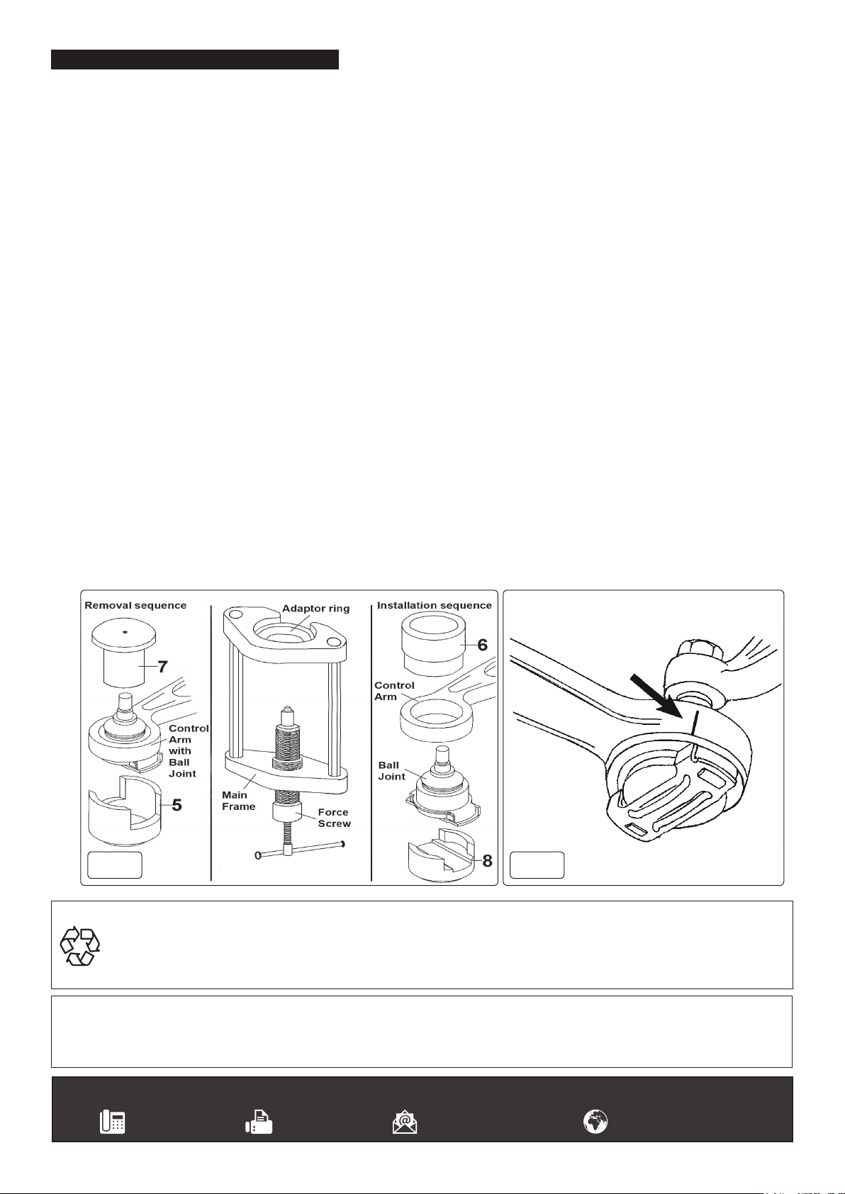
With VSE127H ball joints can be quickly removed and installed in-situ, by selecting and arranging the adaptors within the frame in the
specicorderrequiredforremovalorinstallation,asdetailedbelow.Forceisappliedwiththeforcescrew.
Theadaptorsareidentied5,6,7and8asshowning.1.Itwillsavetimeandmaketheassemblingofthecorrectcongurationfor
removal or installation easier, if the operator reads and becomes familiar with the assembly sequence beforehand.
4.1. PREPARATION REQUIRED TO REMOVE BALL JOINT.
4.1.1. Unscrew nut on stabiliser connection on the control arm.
4.1.2. Unscrew nut on the ball joint until it touches the spring strut and separate the ball joint from axle using a suitable tapered separator
fork.
4.1.3. Unscrew and remove the ball joint nut.
4.1.4. Push the axle journal outward to give access to the ball joint/control arm, and support steering knuckle in position.
4.2. REMOVINGBALLJOINT.(Seeg.1.foradaptorassemblysequence).
4.2.1. Fit adaptor 7 over the ball joint gaiter and locate it in the rubber bonded joint recess.
4.2.2. Position the open end of adaptor 5 over the lower part of the ball joint to rest on underside of the control arm face.
4.2.3. Ensure the force screw is well lubricated and unscrew to give maximum opening within the frame.
4.2.4. Holding the adaptors in place, position the frame over the ball joint and adaptor assembly, locating the recess in adaptor 7 in the top of
the frame.
4.2.5. Screw in force screw so that the bearing assembly aligns with the recess in adaptor 5.
4.2.6. Continue to screw in the force screw assembly to extract the ball joint out of the control arm.
4.2.7. Remove any rust from the lower face of the control arm using a wire brush and clean the bore.
8DO NOT APPLY GREASE. Control arm bore and ball joint must be clean and free from grease.
4.3. INSTALLINGNEWBALLJOINT.(Seeg.1foradaptorassemblysequence).
4.4. Fitadaptor6overcontrolarm(g.1).
4.5. Insert adaptor and ball joint assembly into underside of control arm bore.
IMPORTANT: It is essential to ensure the ball joint is correctly and accurately aligned with the installation position marked on the
controlarmpriortoremovalofoldballjoint(g.2).Placeopenendofadaptor8onthebottomoftheballjointandpositiontheframein
alignment with the joint.
4.6. Lubricate the force screw well and screw it in until the bearing locates in the recess in the bottom of adaptor 8.
4.7. Continue to turn the force screw to press the ball joint FULLY HOME into the control arm.
4.8. RE-ASSEMBLY.
4.8.1. Screw a new self locking nut on ball joint.
4.8.2. To assist when tightening the nut, hold up the ball joint/control arm with a jack.
4.8.3. Replaceselflockingnutandtwasheronstabiliserconnectiononthecontrolarm.
4.8.4. Tightenallnutstospeciedtorque
Sealey Group, Kempson Way, Suffolk Business Park, Bury St Edmunds, Suffolk. IP32 7AR
01284 757500 01284 703534 sales@sealey.co.uk www.sealey.co.uk
Note: It is our policy to continually improve products and as such we reserve the right to alter data, specifications and component parts without prior
notice.
Important: No Liability is accepted for incorrect use of this product.
Warranty: Guarantee is 12 months from purchase date, proof of which is required for any claim.
ENVIRONMENT PROTECTION
Recycle unwanted materials instead of disposing of them as waste. All tools, accessories and packaging should be sorted, taken to
a recycling centre and disposed of in a manner which is compatible with the environment. When the product becomes completely
unserviceable and requires disposal, drain any fluids (if applicable) into approved containers and dispose of the product and fluids
according to local regulations.
VSE127H Issue:2 (2,4) -14/03/19
Original Language Version
© Jack Sealey Limited
fig.1fig.2


