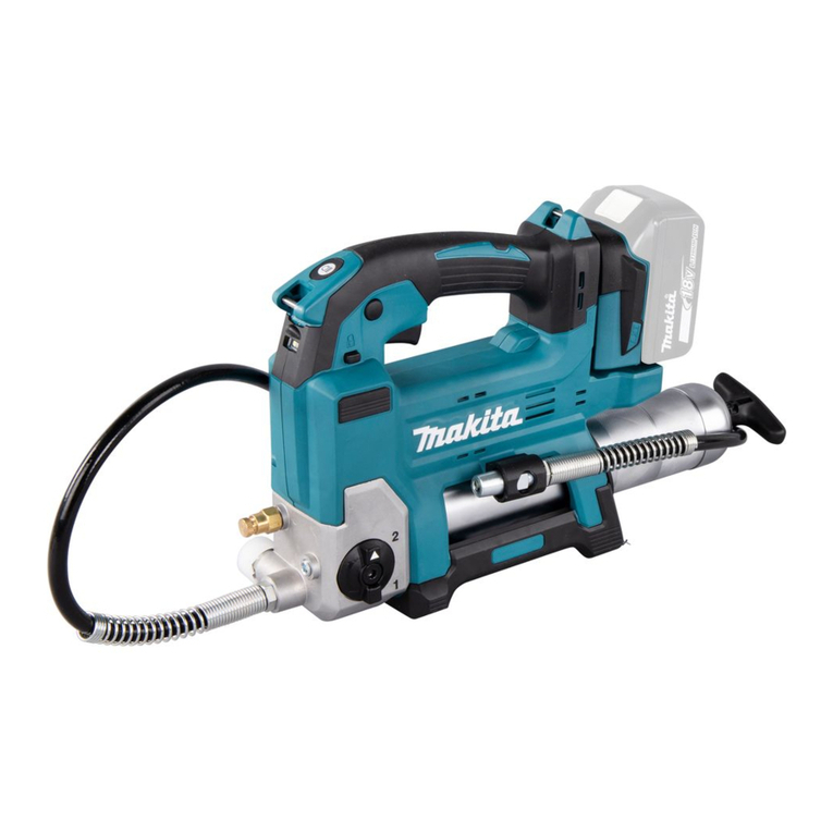
Makita DGP180 User manual

DGP180
EN Cordless Grease Gun INSTRUCTION MANUAL 8
SL Brezžična pištola za mast NAVODILA ZA UPORABO 17
SQ Pistoletë me bateri për
aplikimin e grasos MANUALI I PËRDORIMIT 26
BG Акумулаторен пистолет за
гресиране РЪКОВОДСТВО ЗА
ЕКСПЛОАТАЦИЯ 35
HR Bežični čekić za
podmazivanje PRIRUČNIK S UPUTAMA 45
МК Безжичен пиштол за
подмачкување УПАТСТВО ЗА УПОТРЕБА 54
SR Бежични пиштољ за мазиво УПУТСТВО ЗА УПОТРЕБУ 64
RO Pistol de gresat cu
acumulator MANUAL DE INSTRUCŢIUNI 74
UK Акумуляторний шприц для
мастила ІНСТРУКЦІЯ З
ЕКСПЛУАТАЦІЇ 83
RU Аккумуляторный
смазочный шприц РУКОВОДСТВО ПО
ЭКСПЛУАТАЦИИ 93

11
1
2
13
14
12
16
17
2
5
5
3
4
15
6
8
9
10
7
Fig.1
2
1
3
Fig.2
1
2
Fig.3
BA
1
1
2
3
Fig.4
2
1
Fig.5
2

1
Fig.6
1
Fig.7
1
Fig.8
1
Fig.9
12
Fig.10
1
2
Fig.11
1
2
1
2
Fig.12
3

1
2
3
Fig.13
1
Fig.14
1
3
2
Fig.15
1
Fig.16
1
2
Fig.17
Fig.18
Fig.19
Fig.20
4

Fig.21
1
Fig.22
Fig.23
1
3
2
Fig.24
5
1
2
3
4
Fig.25
Fig.26
1
Fig.27
Fig.28
5

1
Fig.29
Fig.30
Fig.31
Fig.32
Fig.33
1
2
Fig.34
1
34
5
2
Fig.35
1
3
2
Fig.36
6

1
2
Fig.37
Fig.38
1
2
Fig.39
1
Fig.40
Fig.41
1
2
Fig.42
1
Fig.43
7

8ENGLISH
ENGLISH (Original instructions)
SPECIFICATIONS
Model: DGP180
Rated voltage D.C. 18 V
Grease capacity
(with A-type barrel)
Cartridge 410 g
Bulk 455 g
Grease capacity
(with B-type barrel)
Cartridge 450 g
Bulk 570 g
Maximum operating pressure 69 MPa
Maximum ow rate Slow speed mode 145 ml/min
Auto speed mode 290 ml/min
Applicable grease type NLGI No.0 - No.2
Hose length 1,200 mm
Overall length With A-type barrel 411 mm
With B-type barrel 449 mm
Net weight 4.8 - 6.1 kg
NOTE: The barrel type (A-type or B-type) varies depending on the country.
• Due to our continuing program of research and development, the specications herein are subject to change
without notice.
• Specications and battery cartridge may dier from country to country.
• The weight may dier depending on the attachment(s), including the battery cartridge. The lightest and heavi-
est combinations, according to EPTA-Procedure 01/2014, are shown in the table.
Applicable battery cartridge and charger
Battery cartridge BL1815N / BL1820B / BL1830B / BL1840B / BL1850B / BL1860B
Charger DC18RC / DC18RD / DC18RE / DC18SD / DC18SE / DC18SF /
DC18SH
• Some of the battery cartridges and chargers listed above may not be available depending on your region of
residence.
WARNING: Only use the battery cartridges and chargers listed above. Use of any other battery cartridges
and chargers may cause injury and/or re.
Intended use
This tool is intended for dispensing grease.
Noise
The typical A-weighted noise level determined accord-
ing to EN62841-1:
Sound pressure level (LpA) : 76 dB(A)
Uncertainty (K) : 3 dB(A)
NOTE: The declared noise emission value(s) has
been measured in accordance with a standard test
method and may be used for comparing one tool with
another.
NOTE: The declared noise emission value(s)
may also be used in a preliminary assessment of
exposure.
WARNING: Wear ear protection.
WARNING: The noise emission during actual
use of the power tool can dier from the declared
value(s) depending on the ways in which the
tool is used especially what kind of workpiece is
processed.
WARNING: Be sure to identify safety mea-
sures to protect the operator that are based on an
estimation of exposure in the actual conditions of
use (taking account of all parts of the operating
cycle such as the times when the tool is switched
o and when it is running idle in addition to the
trigger time).

9ENGLISH
Vibration
The vibration total value (tri-axial vector sum) deter-
mined according to EN62841-1:
Vibration emission (ah) : 2.5 m/s2or less
Uncertainty (K) : 1.5 m/s2
NOTE: The declared vibration total value(s) has been
measured in accordance with a standard test method
and may be used for comparing one tool with another.
NOTE: The declared vibration total value(s) may also
be used in a preliminary assessment of exposure.
WARNING: The vibration emission during
actual use of the power tool can dier from the
declared value(s) depending on the ways in which
the tool is used especially what kind of workpiece
is processed.
WARNING: Be sure to identify safety mea-
sures to protect the operator that are based on an
estimation of exposure in the actual conditions of
use (taking account of all parts of the operating
cycle such as the times when the tool is switched
o and when it is running idle in addition to the
trigger time).
EC Declaration of Conformity
For European countries only
The EC declaration of conformity is included as Annex A
to this instruction manual.
SAFETY WARNINGS
General power tool safety warnings
WARNING: Read all safety warnings, instruc-
tions, illustrations and specications provided
with this power tool. Failure to follow all instructions
listed below may result in electric shock, re and/or
serious injury.
Save all warnings and instruc-
tions for future reference.
The term "power tool" in the warnings refers to your
mains-operated (corded) power tool or battery-operated
(cordless) power tool.
Cordless grease gun safety warnings
1. Hold the tool rmly.
2. Do not operate the tool near ame. The grease
may be ammable.
3. Use only grease that meets the specications
stated in this instruction manual. Installing a
dierent type of grease or any materials other than
grease may cause failure.
4.
Do not install any materials other than grease, such
as oil. It may spout out of the tool and get into eyes.
5. Do not carry the tool by the exible hose or the
rod handle.
6. Wear goggles when using the tool.
7. Check the exible hose before each use. Do
not use the hose if it is kinked or damaged. The
hose may be ruptured by high pressure and the
grease gets into eyes.
8. Make sure the rod is secured rmly. The rod
may move accidently and cause a pinching.
9. Read and follow the instructions of grease
manufacture before usage.
10. Keep hands and clothes away from the rod of
the rod handle. Otherwise your nger or clothes
may be pinched.
11. Wipe o grease adhering on the tool. Otherwise
it may cause slipping and result in an injury.
12. Do not bend the exible hose forcibly or stamp
it. Doing so may cause a breakage or deformation
of the hose.
13. Do not point the adapter at anyone in the
vicinity.
14. Use the exible hose only specied by Makita.
Use of any other hose might present a risk of
injury.
SAVE THESE INSTRUCTIONS.
Important safety instructions for
battery cartridge
1. Before using battery cartridge, read all instruc-
tions and cautionary markings on (1) battery
charger, (2) battery, and (3) product using
battery.
2. Do not disassemble or tamper with the battery
cartridge. It may result in a re, excessive heat,
or explosion.
3. If operating time has become excessively
shorter, stop operating immediately. It may
result in a risk of overheating, possible burns
and even an explosion.
4. If electrolyte gets into your eyes, rinse them
out with clear water and seek medical atten-
tion right away. It may result in loss of your
eyesight.
5. Do not short the battery cartridge:
(1) Do not touch the terminals with any con-
ductive material.
(2) Avoid storing battery cartridge in a con-
tainer with other metal objects such as
nails, coins, etc.
(3) Do not expose battery cartridge to water
or rain.
A battery short can cause a large current
ow, overheating, possible burns and even a
breakdown.
6. Do not store and use the tool and battery car-
tridge in locations where the temperature may
reach or exceed 50 °C (122 °F).
7. Do not incinerate the battery cartridge even if
it is severely damaged or is completely worn
out. The battery cartridge can explode in a re.
8. Do not nail, cut, crush, throw, drop the battery
cartridge, or hit against a hard object to the
battery cartridge. Such conduct may result in a
re, excessive heat, or explosion.
10 ENGLISH
9. Do not use a damaged battery.
10. The contained lithium-ion batteries are subject
to the Dangerous Goods Legislation require-
ments.
For commercial transports e.g. by third parties,
forwarding agents, special requirement on pack-
aging and labeling must be observed.
For preparation of the item being shipped, consult-
ing an expert for hazardous material is required.
Please also observe possibly more detailed
national regulations.
Tape or mask o open contacts and pack up the
battery in such a manner that it cannot move
around in the packaging.
11. When disposing the battery cartridge, remove
it from the tool and dispose of it in a safe
place. Follow your local regulations relating to
disposal of battery.
12. Use the batteries only with the products
specied by Makita. Installing the batteries to
non-compliant products may result in a re, exces-
sive heat, explosion, or leak of electrolyte.
13. If the tool is not used for a long period of time,
the battery must be removed from the tool.
14. During and after use, the battery cartridge may
take on heat which can cause burns or low
temperature burns. Pay attention to the han-
dling of hot battery cartridges.
15. Do not touch the terminal of the tool imme-
diately after use as it may get hot enough to
cause burns.
16. Do not allow chips, dust, or soil stuck into the
terminals, holes, and grooves of the battery
cartridge. It may cause heating, catching re,
burst and malfunction of the tool or battery car-
tridge, resulting in burns or personal injury.
17. Unless the tool supports the use near
high-voltage electrical power lines, do not use
the battery cartridge near high-voltage electri-
cal power lines. It may result in a malfunction or
breakdown of the tool or battery cartridge.
18. Keep the battery away from children.
SAVE THESE INSTRUCTIONS.
CAUTION: Only use genuine Makita batteries.
Use of non-genuine Makita batteries, or batteries that
have been altered, may result in the battery bursting
causing res, personal injury and damage. It will
also void the Makita warranty for the Makita tool and
charger.
Tips for maintaining maximum
battery life
1. Charge the battery cartridge before completely
discharged. Always stop tool operation and
charge the battery cartridge when you notice
less tool power.
2. Never recharge a fully charged battery car-
tridge. Overcharging shortens the battery
service life.
3. Charge the battery cartridge with room tem-
perature at 10 °C - 40 °C (50 °F - 104 °F). Let
a hot battery cartridge cool down before
charging it.
4. When not using the battery cartridge, remove
it from the tool or the charger.
5. Charge the battery cartridge if you do not use
it for a long period (more than six months).
PARTS DESCRIPTION
► Fig.1
1Switch trigger 2Lock button 3Lamp switch
4Lamp 5Trigger-lock button 6Speed mode changing knob
7Air drain 8Filler port plug 9Flexible hose
10 Adapter 11 Strap hole 12 Battery cartridge
13 Barrel 14 Rod handle 15 Hose holder
16 Pressure relief valve 17 Shoulder strap - -

11 ENGLISH
FUNCTIONAL DESCRIPTION
CAUTION: Always be sure that the tool is
switched o and the battery cartridge is removed
before adjusting or checking function on the tool.
Installing or removing battery cartridge
CAUTION: Always switch o the tool before
installing or removing of the battery cartridge.
CAUTION: Hold the tool and the battery car-
tridge rmly when installing or removing battery
cartridge. Failure to hold the tool and the battery
cartridge rmly may cause them to slip o your hands
and result in damage to the tool and battery cartridge
and a personal injury.
► Fig.2: 1. Red indicator 2. Button 3. Battery cartridge
To remove the battery cartridge, slide it from the tool
while sliding the button on the front of the cartridge.
To install the battery cartridge, align the tongue on the
battery cartridge with the groove in the housing and slip
it into place. Insert it all the way until it locks in place
with a little click. If you can see the red indicator as
shown in the gure, it is not locked completely.
CAUTION: Always install the battery cartridge
fully until the red indicator cannot be seen. If not,
it may accidentally fall out of the tool, causing injury to
you or someone around you.
CAUTION: Do not install the battery cartridge
forcibly. If the cartridge does not slide in easily, it is
not being inserted correctly.
Tool / battery protection system
The tool is equipped with a tool/battery protection sys-
tem. This system automatically cuts o power to the
motor to extend tool and battery life. The tool will auto-
matically stop during operation if the tool or battery is
placed under one of the following conditions:
Overload protection
When the tool/battery is operated in a manner that causes
it to draw an abnormally high current, the tool automatically
stops without any indication. In this situation, turn the tool
o and stop the application that caused the tool to become
overloaded. Then turn the tool on to restart.
Overheat protection
When the tool or battery is overheated, the tool stops
automatically and the lamp blinks. In this case, let the
tool and battery cool before turning the tool on again.
Overdischarge protection
When the battery capacity is not enough, the tool stops automatically.
In this case, remove the battery from the tool and charge the battery.
NOTE: The protection system may become more
likely to work depending on the ambient temperature
or the type and condition of grease.
Protections against other causes
Protection system is also designed for other causes
that could damage the tool and allows the tool to stop
automatically. Take all the following steps to clear the
causes, when the tool has been brought to a temporary
halt or stop in operation.
1. Turn the tool o, and then turn it on again to
restart.
2. Charge the battery(ies) or replace it/them with
recharged battery(ies).
3. Let the tool and battery(ies) cool down.
If no improvement can be found by restoring protection
system, then contact your local Makita Service Center.
Indicating the remaining battery
capacity
Only for battery cartridges with the indicator
► Fig.3: 1. Indicator lamps 2. Check button
Press the check button on the battery cartridge to indi-
cate the remaining battery capacity. The indicator lamps
light up for a few seconds.
Indicator lamps Remaining
capacity
Lighted O Blinking
75% to 100%
50% to 75%
25% to 50%
0% to 25%
Charge the
battery.
The battery
may have
malfunctioned.
NOTE: Depending on the conditions of use and the
ambient temperature, the indication may dier slightly
from the actual capacity.
NOTE: The rst (far left) indicator lamp will blink when
the battery protection system works.

12 ENGLISH
Switch action
CAUTION: Before installing the battery car-
tridge into the tool, always check to see that the
switch trigger actuates properly and returns to
the "OFF" position when released.
CAUTION: When not operating the tool,
depress the trigger-lock button from "A" side to
lock the switch trigger in the OFF position.
To prevent the switch trigger from accidentally pulled,
the trigger-lock button is provided.
To start the tool, depress the trigger-lock button from "B"
side and pull the switch trigger.
Tool speed is increased by increasing pressure on the
switch trigger. Release the switch trigger to stop. After
use, always press in the trigger-lock button from "A" side.
For continuous operation, pull the switch trigger and
then push in the lock button. To stop the tool from the
locked position, pull the switch trigger fully to unlock.
► Fig.4: 1. Switch trigger 2. Lock button 3. Trigger-
lock button
Lighting up the front lamp
CAUTION: Do not look in the light or see the
source of light directly.
Press the lamp switch to light up the lamp. Press the lamp switch
again to turn o the lamp. When the tool is left without any operation
for about 60 seconds with the motor stopped, the lamp goes out.
► Fig.5: 1. Lamp 2. Lamp switch
NOTICE: Use a dry cloth to wipe the dirt o the lens
of the lamp. Be careful not to scratch the lens of lamp,
or it may lower the illumination.
Selecting the speed mode
NOTICE: Change the speed mode only after the
tool comes to a complete stop.
The tool employs the speed mode changing knob. Turn
the knob so that the arrow on the knob points toward
one of the two modes below;
1
Slow speed mode: Dispense grease at constant slow speed.
2
Auto speed mode: Apply grease while varying the ow rate
automatically according to pressure of supply destination.
► Fig.6: 1. Speed mode changing knob
Pressure relief valve
When the internal pressure in the tool exceeds a certain
level, grease comes out from the pressure relief valve to
lower the internal pressure.
► Fig.7: 1. Pressure relief valve
CAUTION: Do not remove or make any adjust-
ment to the pressure relief valve.
CAUTION: Do not remove the cover of pres-
sure relief valve. Otherwise grease may spout out of
the pressure relief valve and get into eyes.
ASSEMBLY
CAUTION: Always be sure that the tool is
switched o and the battery cartridge is removed
before carrying out any work on the tool.
Removing or installing barrel
To remove the barrel, screw it as illustrated.
► Fig.8: 1. Barrel
To install the barrel, insert it into the tool then screw in
reverse.
► Fig.9: 1. Barrel
Rod handle
NOTICE: Do not pull the rod handle with valve
for air drain fastened while the barrel installed in
the tool. Make sure the valve for air drain is loos-
ened. Failure to do so may cause malfunction.
Pull the rod handle when installing grease in the barrel.
► Fig.10: 1. Rod handle 2. Rod
To lock the rod handle fully pulled, pull the rod handle
until the groove on the rod can be seen, and then hook
the groove onto the slot. To unlock the rod handle,
unhook the groove so the rod moves forward.
► Fig.11: 1. Groove 2. Slot
CAUTION: Make sure the rod handle is locked
rmly. Otherwise it may be unlocked accidentally and
cause a pinching.
Hose holder
The hose holder can be attached to either side of the
tool with the screw.
► Fig.12: 1. Hose holder 2. Screw
Shoulder strap
WARNING: Never use the strap hole for lan-
yard (tether strap). Doing so may result in serious
injury because the strap hole is not intended for a
safety device for fall prevention.
WARNING: When carrying the tool, keep
holding the tool even if when using the shoulder
strap. Carrying the tool using only the shoulder strap
makes it unstable. The shoulder strap may come o
or the tool hit other objects and cause injury.
Attach the hooks of the shoulder strap onto the mounts
of the strap holes as shown in the gure.
► Fig.13: 1. Shoulder strap 2. Hook 3. Mount

13 ENGLISH
OPERATION
Grease supply
WARNING: Make sure to read the instruction
manuals of the grease and/or other instruments
and replace the following contents as necessary.
Misuse or failure to follow the instructions may dam-
age the tool or cause an injury.
NOTICE: When using the barrel with the old
grease remains, remove the barrel and purge the
old grease according to the section for purge of
grease.
There are following ways to provide grease:
Installing grease cartridge
(commercially-bought) in the barrel
NOTICE: (For A-type barrel only)
Use the grease cartridge whose brim can be
hooked on the end surface of the barrel.
NOTICE: (For B-type/C-type barrel only)
Use the grease cartridge whose brim can be
hooked on the inside step of the barrel.
1. Loosen the valve for air drain.
► Fig.14: 1. Valve
2. Fully pull the rod handle and lock it.
► Fig.15: 1. Groove 2. Rod 3. Rod handle
3. Remove the barrel from the tool.
► Fig.16: 1. Barrel
4. Remove the plastic cap of the grease cartridge
and insert the grease cartridge into the barrel.
► Fig.17: 1. Grease cartridge (commercially-bought)
2. Pull tab
5. Remove the pull tab of the grease cartridge then
install the barrel to the tool.
If there is a gap between the brim of the grease car-
tridge and the barrel, screw the barrel into the tool while
pushing the barrel forward.
► Fig.18
6. Release the rod handle.
► Fig.19
7. Eject the air that remains in the ow path of the
grease.
► Fig.20
8. Fasten the valve for air drain when you see the
grease coming out of the hole.
► Fig.21
NOTE: If the tool cannot pour grease accurately, air
may remain in the ow path of the grease. Loosen
the valve for air drain and eject the air. (Refer to the
section for ejection of air.)
Filling grease in the barrel
from a bulk container
(commercially-bought)
1. Loosen the valve for air drain.
2. Fully pull the rod handle and lock it.
3. Remove the barrel from the tool.
Unlock the rod handle and move the rod forward gently.
4. Dip the tip of the barrel in the grease and then
pull the rod handle. The grease is pumped up into the
barrel.
► Fig.22: 1. Bulk container (commercially-bought)
5. Fully pull the rod handle and lock it.
► Fig.23
6. Install the barrel to the tool and then unlock the
rod handle.
7. Eject the air that remains in the ow path of the
grease.
8. Fasten the valve for air drain when you see the
grease coming out of the hole.
NOTICE: When locking the rod handle, make
sure the rod handle is locked rmly. Otherwise the
rod handle get unlocked unintentionally, the grease
comes out from the barrel.
NOTE: (For B-type/C-type barrel only)
The amount of grease lling should be below the
screw groove line. Otherwise grease will overow
when installing the barrel to the tool.
► Fig.24: 1. Barrel (B-type/C-type) 2. Screw groove
3. Grease
NOTE: If the tool cannot pour grease accurately, air
may remain in the ow path of the grease. Loosen
the valve for air drain and eject the air. (Refer to the
section for ejection of air.)
You can also ll grease into the barrel using a ller
pump (commercially-bought) attached to the bulk
container.
1. Remove the barrel from the tool.
2. Wrap thread seal tape around the thread part of
the loader tting (commercially-bought).
3. Remove the ller port plug. Attach a loader tting
to the ller port.
4. Install the barrel to the tool. (The rod handle is
unlocked.)
5. Make sure that the valve for air drain is fastened.
Connect the loader tting to the tting of the ller pump.
► Fig.25: 1. Filler port plug 2. Filler port 3. Loader
tting (commercially-bought) 4. Filler pump
(commercially-bought) 5. Fitting
6. Operate the ller pump. The rod of the rod handle
will be pushed out as the barrel is lled with grease.
► Fig.26
7. Disconnect the loader tting from the tting of the
ller pump.
8. Eject the air that remains in the ow path of the
grease.

14 ENGLISH
9. Fasten the valve for air drain when you see the
grease coming out of the hole.
WARNING: Use a low-pressure loader tting
only. Never use a high-pressure loader tting
otherwise it may damage the tool and cause a
personal injury.
CAUTION: Hold the tool rmly when lling the
grease by using a ller pump. The tool may fall and
cause an injury.
NOTICE: Stop lling the grease when you see
the groove on the rod. Otherwise the grease leak-
age may occur.
NOTE: If the tool cannot pour grease accurately, air
may remain in the ow path of the grease. Loosen
the valve for air drain and eject the air. (Refer to the
section for ejection of air.)
Ejection of air
If air remains in the ow path of the grease, the tool
cannot pour grease accurately. Eject the air before each
use and also when the tool seems to work improperly
due to air.
1. To eject air from inside of the tool, loosen the valve
for air drain. Air comes out from the hole for air drain.
2. Fasten the valve when you see the grease coming
out of the hole.
► Fig.27: 1. Valve
WARNING: Wear the protective goggles when
ejecting the air.
CAUTION: Wipe o the grease that comes
out from the air drain with a dry cloth or the like.
Otherwise it may cause slipping and result in an
injury.
Dispensing the grease
In the following cases, purge the old grease inside the
tool before use;
— When using the tool for the rst time or;
— When using dierent type of the grease from
previous use.
With the new grease lled in the barrel, run the tool
for a while until the old grease is pushed out from the
adapter.
NOTICE: Do not connect the adapter to the
grease nipple until the old grease is purged. If
dierent kinds of grease are mixed, the performance
of the grease may decline.
NOTE: The tool has been tested at the factory and
small amount of the grease remains.
Perform the following procedure to dispense the
grease.
CAUTION: Always check the speed mode
before operation.
NOTICE: Before connecting the adapter to the
grease nipple, always make sure that the tool
dispenses grease properly.
NOTICE: Do not connect the adapter to the
grease nipple forcibly.
1. Wipe the adapter and the grease nipple before
connecting. Push the adapter straight at the grease
nipple.
2. Pull the switch trigger to dispense the grease.
► Fig.28
3. When dispensing the grease is nished, remove
the adapter from the grease nipple. Tilt the adapter
slightly to release internal pressure and then remove
the adapter from the grease nipple.
Wipe o the grease from the adapter and the grease
nipple.
NOTICE: Do not leave the tool running even after
the grease depleted. It may shorten the life of the
tool.
NOTE: If the tool cannot pour grease accurately, air
may remain in the ow path of the grease. Loosen
the valve for air drain and eject the air. (Refer to the
section for ejection of air.)
NOTE: If the internal pressure rises while the switch
trigger is not fully pulled, the protection system works
and the motor will stop even though the tool does
not reach the maximum operating pressure. When
injecting the grease at high pressure, pull the switch
trigger fully.
NOTE: The tool stops automatically when the tool
keep running for more than 6 minutes.
In the case that the tool does not
pour grease accurately
If the tool cannot pour grease accurately, air may
remain in the ow path of the grease. Eject the air
according to the following procedure.
1. Loosen the valve for air drain.
► Fig.29: 1. Valve
2. Eject the air that remains in the ow path of the
grease.
► Fig.30
3. Fasten the valve for air drain when you see the
grease coming out of the hole.
► Fig.31

15 ENGLISH
MAINTENANCE
CAUTION: Always be sure that the tool is
switched o and the battery cartridge is removed
before attempting to perform inspection or
maintenance.
NOTICE: Never use gasoline, benzine, thinner,
alcohol or the like. Discoloration, deformation or
cracks may result.
To maintain product SAFETY and RELIABILITY,
repairs, any other maintenance or adjustment should
be performed by Makita Authorized or Factory Service
Centers, always using Makita replacement parts.
Purge of grease
When storing the tool or using the barrel in which the
grease remains, remove the barrel and purge the old
grease in the following procedure.
1. Loosen the valve for air drain.
2. Fully pull the rod handle and lock it.
3. Remove the barrel from the tool.
4. Unlock the rod handle. Keep holding the rod
handle and slowly move the rod handle forward so the
grease gets out of the barrel.
CAUTION: Do not take hand o from the rod
handle. Otherwise the grease pops out vigorously.
NOTICE: Keep dust away from inside of the
barrel. Dust may get clogged in the tool.
NOTICE: Clean the inside of the barrel once
every three months.
OPTIONAL ACCESSORIES
CAUTION: These accessories or attachments
are recommended for use with your Makita tool
specied in this manual. The use of any other
accessories or attachments might present a risk of
injury to persons. Only use accessory or attachment
for its stated purpose.
If you need any assistance for more details regard-
ing these accessories, ask your local Makita Service
Center.
• Adapter
• Flexible hose
• Barrel
• Cartridge barrel
• Shoulder strap
• Lock on adapter
• Angle adapter
• Makita genuine battery and charger
NOTE: Some items in the list may be included in the
tool package as standard accessories. They may
dier from country to country.
Replacing of the adapter
Loosen and remove the old adapter with two wrenches
as illustrated and then tighten the new adapter securely.
► Fig.32
NOTE: If grease leaks from the joint between the
hose and the adapter, wrap thread seal tape around
the thread part of the hose before connecting the
adapter.
Replacing of the exible hose
Loosen and remove the old exible hose with a wrench
as illustrated and then tighten the new exible hose
securely.
► Fig.33
CAUTION: Replace the rubber ring attached
to the connection part of the new exible hose at
the same time. If you replace the exible hose with-
out the rubber ring or with the old rubber ring, grease
may leak and cause an injury.
Changing the barrel
NOTE: The barrel type varies depending on the
country.
NOTE: To install a barrel of dierent type, additional
parts described below are required depending on the
type of the barrel.
Changing the barrel from A-type to
B-type/C-type
1. Remove A-type barrel.
2. Remove the screw and then the sleeve.
► Fig.34: 1. Sleeve 2. Screw
3. Insert the joint with the rubber packing while align-
ing the tab with the groove on the mounting part and
then secure it with screws.
4. Install B-type/C-type barrel.
► Fig.35: 1. Joint 2. Rubber packing 3. Tab 4. Groove
5. Screw
Changing the barrel from B-type/C-
type to A-type
1. Remove B-type/C-type barrel.
2. Unscrew and remove the joint.
► Fig.36: 1. Joint 2. Rubber packing 3. Screw
3. Insert the sleeve into the tool housing, then secure
it with a screw.
4. Install A-type barrel.
► Fig.37: 1. Sleeve 2. Screw

16 ENGLISH
Cartridge barrel
You can see the grease cartridge through the hole on
the cartridge barrel.
► Fig.38
When using the cartridge barrel, transfer the piston
parts from the corresponding barrel to the cartridge
barrel.
► Fig.39: 1. Piston parts 2. Cartridge barrel
If it is hard to pull out the rod handle, follow the proce-
dure below.
1. Insert the empty grease cartridge into the barrel.
► Fig.40: 1. Empty grease cartridge
2. Pull the rod handle and lock it.
► Fig.41
3. Remove the empty grease cartridge from the
barrel.
Lock on adapter
CAUTION: Be careful not to pinch the nger
in the lock on adapter.
CAUTION: Wear the protective goggles.
When removing the lock on adapter from the grease
nipple, the grease may spout out of the tool and
cause an injury.
When connecting the lock on adapter to the grease
nipple, push the lock on adapter straight at the grease
nipple while pulling the lever of the lock on adapter, then
release the lever.
► Fig.42: 1. Lever 2. Lock on adapter
To assemble the lock on adapter, refer to the section for
replacing of the adapter.
Angle adapter
When attaching the angle adapter, push the adapter of
the tool straight to the angle adapter.
► Fig.43: 1. Angle adapter
NOTE: The angle adapter is recommended for
grease injection at relatively low pressure such as
replacement of old grease in joints or sliding parts of
heavy machinery and vehicles.
TROUBLE SHOOTING
Before asking for repairs, conduct your own inspection rst. If you nd a problem that is not explained in the manual,
do not attempt to dismantle the tool. Instead, ask Makita Authorized Service Centers, always using Makita replace-
ment parts for repairs.
State of abnormality Probable cause (malfunction) Remedy
The tool does not pour grease Air remains in the ow path of the
grease. To eject air from inside of the tool, loosen the valve
for air drain.
The valve for air drain is loose. Fasten the valve for air drain.
The grease consistency is high. Use NLGI No.0 - No.2 grease.
The grease is hard due to low ambient/
storage temperature.
Warm grease before use.
No grease inside of the tool. Supply grease into the tool.
You cannot pull the rod handle. The valve for air drain is fastened. Loosen the valve for air drain.
Grease leaks from the adapter. There is wear, damage or dust on the
grease injection port (grease nipple). Clean or replace the grease injection port (grease
nipple).
Adapter is worn out. Replace the adapter.
Grease does not come out of the air
drain valve when ejecting the air.
The air drain valve is not loose enough. Loosen the air drain valve further.
The grease is hard. The air may have already been ejected.
Fasten the valve for air drain, install the battery
cartridge, and turn on the tool to check if the tool
pour grease.

17 SLOVENŠČINA
SLOVENŠČINA (Originalna navodila)
TEHNIČNI PODATKI
Model: DGP180
Nazivna napetost D.C. 18 V
Količina masti (pri posodi tipa A)
Kartuša 410 g
Polnilo 455 g
Količina masti (pri posodi tipa B)
Kartuša 450 g
Polnilo 570 g
Največji delovni tlak 69 MPa
Največja hitrost pretoka Način z nizko hitrostjo 145 ml/min
Način s samodejno hitrostjo 290 ml/min
Dovoljena vrsta masti NLGI št.0–št.2
Dolžina cevi 1.200 mm
Celotna dolžina Pri posodi tipa A 411 mm
Pri posodi tipa B 449 mm
Neto teža 4,8–6,1 kg
OPOMBA: Tip posode (A ali B) se razlikuje glede na državo.
• Ker nenehno opravljamo raziskave in razvijamo svoje izdelke, se lahko tehnični podatki v tem dokumentu
spremenijo brez obvestila.
• Tehnični podatki in baterijski vložki se lahko razlikujejo glede na državo uporabe izdelka.
• Teža se lahko razlikuje glede na priključke, vključno z akumulatorsko baterijo. Najlažja in najtežja kombinacija v
skladu s postopkom EPTA 01/2014 sta prikazani v preglednici.
Uporabna akumulatorska baterija in polnilnik
Baterijski vložek BL1815N / BL1820B / BL1830B / BL1840B / BL1850B / BL1860B
Polnilnik DC18RC / DC18RD / DC18RE / DC18SD / DC18SE / DC18SF /
DC18SH
• Nekatere zgoraj navedene akumulatorske baterije in polnilniki morda v vaši državi prebivališča niso na voljo.
OPOZORILO: Uporabljajte le zgoraj navedene akumulatorske baterije in polnilnike. Uporaba drugih
akumulatorskih baterij in polnilnikov lahko povzroči telesne poškodbe in/ali požar.
Predvidena uporaba
Orodje je namenjeno odmerjanju masti.
Hrup
Običajna A-ovrednotena raven hrupa v skladu z
EN62841-1:
Raven zvočnega tlaka (LpA): 76 dB (A)
Odstopanje (K): 3 dB (A)
OPOMBA: Navedene vrednosti oddajanja hrupa so
bile izmerjene v skladu s standardnimi metodami
testiranja in se lahko uporabljajo za primerjavo orodij.
OPOMBA: Navedene vrednosti oddajanja hrupa
se lahko uporabljajo tudi pri predhodni oceni
izpostavljenosti.
OPOZORILO: Uporabljajte zaščito za sluh.
OPOZORILO: Oddajanje hrupa med dejansko
uporabo električnega orodja se lahko razlikuje od
navedenih vrednosti, odvisno od načina uporabe
orodja in predvsem vrste obdelovanca.
OPOZORILO: Upravljavec mora za lastno
zaščito poznati varnostne ukrepe, ki temeljijo
na oceni izpostavljenosti v dejanskih pogojih
uporabe (poleg časa proženja je treba upoštevati
celoten delovni cikel, vključno s časom, ko je
orodje izklopljeno, in časom, ko deluje v prostem
teku).

18 SLOVENŠČINA
Vibracije
Skupne vrednosti vibracij (vektorska vsota treh osi) v
skladu z EN62841-1:
Emisije vibracij (ah): 2,5 m/s2 ali manj
Odstopanje (K): 1,5 m/s2
OPOMBA: Navedene skupne vrednosti oddajanja
vibracij so bile izmerjene v skladu s standardnimi
metodami testiranja in se lahko uporabljajo za primer-
javo orodij.
OPOMBA: Navedene skupne vrednosti oddajanja
vibracij se lahko uporabljajo tudi pri predhodni oceni
izpostavljenosti.
OPOZORILO: Oddajanje vibracij med
dejansko uporabo električnega orodja se lahko
razlikuje od navedenih vrednosti, odvisno
od načina uporabe orodja in predvsem vrste
obdelovanca.
OPOZORILO: Upravljavec mora za lastno
zaščito poznati varnostne ukrepe, ki temeljijo
na oceni izpostavljenosti v dejanskih pogojih
uporabe (poleg časa proženja je treba upoštevati
celoten delovni cikel, vključno s časom, ko je
orodje izklopljeno, in časom, ko deluje v prostem
teku).
Izjava o skladnosti ES
Samo za evropske države
Izjava ES o skladnosti je vključena v dodatku A, ki je
priložen tem navodilom za uporabo.
VARNOSTNA
OPOZORILA
Splošna varnostna opozorila za
električno orodje
OPOZORILO: Preberite vsa varnostna opo-
zorila in navodila s slikami in tehničnimi podatki,
ki so dobavljeni skupaj z električnim orodjem.
Ob neupoštevanju spodaj navedenih navodil obstaja
nevarnost električnega udara, požara in/ali hudih
telesnih poškodb.
Shranite vsa opozorila in navo-
dila za poznejšo uporabo.
Izraz „električno orodje“ v opozorilih se nanaša na vaše
električno orodje (s kablom) ali baterijsko električno
orodje (brez kabla).
Varnostna opozorila za uporabo
brezžične pištole za mast
1. Trdno držite orodje.
2. Ne uporabljajte orodja v bližini plamena. Mast
je lahko vnetljiva.
3. Uporabite samo mast, ki ustreza tehničnim
podatkom, navedenim v teh navodilih za upo-
rabo. Uporaba drugačne vrste masti ali drugih
materialov lahko povzroči okvaro.
4. Razen masti ne uporabljajte nobenih drugih
materialov, npr. olja. Lahko namreč brizgne iz
orodja in zaide v oči.
5. Orodja ne prenašajte tako, da ga držite za
gibljivo cev ali držalo na drogu.
6. Med uporabo orodja nosite zaščitna očala.
7. Pred vsako uporabo preglejte gibljivo cev.
Če je cev prepognjena ali poškodovana, je ne
uporabljajte. Cev lahko zaradi visokega pritiska
poči in vam lahko mast zaide v oči.
8. Preverite, ali je drog dobro pritrjen. Drog se
lahko po nesreči premakne in se zagozdi.
9. Pred uporabo preberite in upoštevajte navo-
dila proizvajalca masti.
10. Rok in oblačil ne približujte drogu, ki je del
držala droga. V nasprotnem primeru vam lahko
stisne prst ali oblačila.
11.
Obrišite mast z orodja. V nasprotnem primeru vam
lahko zaradi masti zdrsne in pride do poškodbe.
12. Ne upogibajte gibljive cevi na silo oziroma ne
stopajte po njej. S tem lahko namreč cev pred-
rete ali deformirate.
13. Ne usmerjajte adapterja proti osebam v okolici.
14.
Uporabite samo gibljivo cev po priporočilu Makite.
Pri uporabi drugih cevi lahko pride do telesnih poškodb.
SHRANITE TA NAVODILA.
Pomembna varnostna navodila za
akumulatorsko baterijo
1. Pred uporabo baterijskega vložka preberite
vsa navodila in opozorilne oznake na (1) pol-
nilniku akumulatorja, (2) akumulatorju in (3)
izdelku, ki uporablja akumulator.
2. Ne razstavljajte ali spreminjajte akumulatorske
baterije. S tem lahko povzročite požar, preko-
merno vročino ali eksplozijo.
3. Če se je čas delovanja občutno skrajšal, takoj
prenehajte uporabljati orodje. V nasprotnem
primeru lahko pride do pregretja, morebitnih
opeklin in celo eksplozije.
4. Če pride elektrolit v stik z očmi, jih sperite s
čisto vodo in takoj poiščite zdravniško pomoč.
Posledica je lahko izguba vida.
5.
Ne povzročite kratkega stika baterijskega vložka:
(1) Ne dotikajte se priključkov s kakršnim
koli prevodnim materialom.
(2) Izogibajte se shranjevanju baterijskega
vložka v vsebniku z drugimi kovinskimi
predmeti kot so žeblji, kovanci itn.
(3) Ne izpostavljajte baterijskega vložka vodi
ali dežju.

19 SLOVENŠČINA
Kratek stik akumulatorja lahko povzroči velik
električni tok, pregrevanje, morebitne opekline
in celo okvaro.
6. Ne shranjujte in uporabljajte orodja in akumu-
latorske baterije na mestih, kjer lahko tempera-
tura doseže ali preseže 50 °C (122 °F).
7. Ne sežigajte baterijskega vložka, tudi če je
hudo poškodovan ali v celoti izpraznjen.
Baterijski vložek lahko v ognju eksplodira.
8. Ne pribijajte, režite, drobite, mečite, spuščajte
akumulatorske baterije oziroma ne udarjajte
z akumulatorsko baterijo po trdem predmetu.
Takšno ravnanje lahko povzroči požar, preko-
merno vročino ali eksplozijo.
9. Ne uporabljajte poškodovanih akumulatorjev.
10. Priložene litij-ionske baterije ustrezajo zahte-
vam zakonodaje v zvezi z nevarnim blagom.
Za komercialne prevoze, npr. tiste, ki jih opravljajo
tretje stranke in carinski posredniki, je treba upo-
števati posebne zahteve v zvezi z embalažo in
označevanjem.
Med postopkom priprave na odpremo izdelka se
je treba posvetovati s strokovnjakom za nevarne
snovi. Pri tem upoštevajte tudi podrobnejše nacio-
nalne predpise.
Odprte stike oblepite z lepilnim trakom ali jih dru-
gače zaščitite, baterijo pa zapakirajte tako, da se v
embalaži ne more premikati.
11. Ko odstranjujete akumulatorsko baterijo, jo
vzemite iz orodja in varno zavrzite. Upoštevajte
lokalne uredbe glede odlaganja baterije.
12. Baterije uporabljajte le z izdelki, ki jih določi
Makita. Če namestite baterije v neskladne izdelke,
lahko pride do požara, pregrevanja, eksplozije ali
puščanja elektrolita.
13. Če orodja dlje časa ne uporabljate, morate iz
njega odstraniti baterijo.
14. Med uporabo in po uporabi lahko akumu-
latorska baterija postane vroča in povzroči
opekline. Z vročimi akumulatorskimi baterijami
ravnajte pazljivo.
15. Ne dotikajte se priključka orodja takoj po upo-
rabi, ker se lahko dovolj segreje, da povzroči
opekline.
16. Ne dovolite, da bi se v priključke, odprtine in
utore akumulatorske baterije zlepili ostružki,
prah ali zemlja. To lahko povzroči pregrevanje,
požar, razpočenje in okvaro orodja ali akumula-
torske baterije ter privede do opeklin ali drugih
telesnih poškodb.
17. Razen če orodje podpira uporabo v bližini
visokonapetostnih električnih vodov, akumula-
torske baterije ne uporabljajte v bližini visoko-
napetostnih električnih vodov. Takšna uporaba
lahko povzroči motnje v delovanju ali okvaro
orodja oziroma akumulatorske baterije.
18. Baterijo hranite izven dosega otrok.
SHRANITE TA NAVODILA.
POZOR: Uporabljajte le originalne baterije
Makita. Če uporabljate neoriginalne baterije Makita
ali baterije, ki so bile spremenjene, lahko pride do
eksplozije baterije in posledično do požara, telesnih
poškodb ali materialne škode. S takšno uporabo
boste tudi razveljavili garancijo Makita za orodje in
polnilnik Makita.
Nasveti za ohranjanje največje
zmogljivosti akumulatorja
1. Napolnite baterijski vložek, preden se v celoti
izprazni. Ko opazite, da ima orodje manjšo
moč, vedno ustavite delovanje orodja in napol-
nite baterijski vložek.
2. Nikoli znova ne polnite popolnoma napol-
njenega baterijskega vložka. Prenapolnjenje
skrajša življenjsko dobo akumulatorja.
3. Baterijski vložek s sobno temperaturo pol-
nite pri temperaturi okolja od 10 °C do 40 °C.
Počakajte, da se vroč baterijski vložek pred
polnjenjem ohladi.
4. Ko akumulatorske baterije ne uporabljate, jo
odstranite iz orodja ali polnilnika.
5. Če baterijskega vložka ne uporabljate dalj časa
(več kot 6 mesecev), ga napolnite.
OPIS DELOV
► Sl.1
1Sprožilec 2Gumb za zaklep 3Stikalo za lučko
4Lučka 5Gumb za zaklep sprožilca 6Gumb za spreminjanje načina
hitrosti
7Odvod zraka 8Čep priključka za polnjenje 9Gibljiva cev
10 Adapter 11 Odprtina za jermen 12 Akumulatorska baterija
13 Posoda 14 Držalo droga 15 Držalo cevi
16 Tlačni varnostni ventil 17 Ramenski jermen - -

20 SLOVENŠČINA
OPIS DELOVANJA
POZOR: Pred nastavljanjem ali preizkusom
delovanja orodja se prepričajte, ali je orodje
izključeno in ali je akumulatorska baterija
odstranjena.
Nameščanje ali odstranjevanje
akumulatorske baterije
POZOR: Vedno izklopite orodje, preden name-
stite ali odstranite akumulatorsko baterijo.
POZOR: Kadar nameščate ali odstranjujete
akumulatorsko baterijo, trdno držite orodje in
akumulatorsko baterijo. Če orodja in akumulatorske
baterije ne držite trdno, se lahko zgodi, da vam zdr-
sneta iz rok, posledica pa je lahko poškodba orodja in
akumulatorske baterije ter telesna poškodba.
► Sl.2: 1. Rdeči indikator 2. Gumb 3. Baterijski vložek
Če želite odstraniti akumulatorsko baterijo, jo potisnite
iz orodja, pri tem pa pomikajte gumb na sprednji strani
vložka.
Akumulatorsko baterijo vstavite tako, da poravnate
jeziček na bateriji z utorom na ohišju in jo potisnete v
ležišče. Potisnite jo do konca, da se zaskoči. Če vidite
rdeči indikator, kot je prikazano na sliki, se akumulator-
ska baterija ni ustrezno zaskočila.
POZOR: Vedno namestite akumulatorsko
baterijo tako, da rdeči indikator ni več viden. Če
tega ne upoštevate, lahko baterija nepričakovano
pade iz orodja in poškoduje vas ali osebe v neposre-
dni bližini.
POZOR: Ne nameščajte akumulatorske bate-
rije s silo. Če se akumulatorska baterija ne zaskoči
zlahka, ni pravilno vstavljena.
Zaščitni sistem orodja/akumulatorja
Orodje je opremljeno z zaščitnim sistemom za orodje/
akumulator. Sistem samodejno prekine napajanje
orodja, da podaljša življenjsko dobo orodja in akumula-
torja. Orodje se samodejno zaustavi med delovanjem,
če orodje ali akumulator delujeta pod naslednjimi
pogoji:
Zaščita pred preobremenitvijo
Kadar orodje/akumulator uporabljate na način, ki
povzroča uporabo neobičajno visokega toka, se orodje
samodejno ustavi brez kakršnih koli znakov. V tem
primeru izklopite orodje in prenehajte izvajati delo, ki je
povzročilo preobremenitev orodja. Nato vklopite orodje
in ga znova zaženite.
Zaščita pred pregrevanjem
Če je orodje ali akumulator pregret, se orodje samo-
dejno ustavi in lučka začne utripati. V tem primeru poča-
kajte, da se orodje in akumulator ohladi, preden znova
vklopite orodje.
Zaščita pred izpraznjenjem
Ko je zmogljivost akumulatorja prenizka, se orodje
samodejno ustavi. V tem primeru odstranite akumulator
iz orodja in ga napolnite.
OPOMBA: Delovanje zaščitnega sistema je lahko
odvisno od temperature okolice oziroma vrste in
stanja masti.
Zaščita pred drugimi vzroki
Sistem zaščite je zasnovan tudi za druge vzroke, ki bi
lahko povzročili poškodbe orodja, in omogoča samo-
dejno ustavitev orodja. Kadar se orodje začasno ustavi
ali preneha delovati, izvedite vse naslednje korake, da
odpravite vzroke.
1. Izklopite orodje in ga nato vklopite, da ga znova
zaženete.
2. Napolnite baterijo ali jo zamenjajte z napolnjeno
baterijo (po potrebi ponovite postopek še za drugo
baterijo).
3. Počakajte, da se orodje in baterija ohladita.
Če z obnovitvijo sistema zaščite ne odpravite težave, se
obrnite na lokalni servisni center Makita.
Prikazuje preostalo raven
napolnjenosti akumulatorja
Samo za akumulatorske baterije z indikatorjem
► Sl.3: 1. Indikatorske lučke 2. Gumb za preverjanje
Pritisnite gumb za preverjanje na baterijskem vložku,
da preverite raven napolnjenosti akumulatorja.
Indikatorske lučke na kratko zasvetijo.
Indikatorske lučke Prikaz pre-
ostale ravni
napolnjenosti
Sveti Ne sveti Utripa
od 75 % do
100 %
od 50 % do
75 %
od 25 % do
50 %
od 0 % do
25 %
Napolnite
akumulator.
Akumulator
je morda
okvarjen.
OPOMBA: Odvisno od pogojev uporabe in okoljske
temperature se označba lahko nekoliko razlikuje od
dejanske napolnjenosti.
OPOMBA: Prva opozorilna lučka (skrajno levo) bo
utripala, ko sistem za zaščito akumulatorja deluje.
Other manuals for DGP180
7
Table of contents
Languages:
Other Makita Tools manuals

Makita
Makita HR2631F User manual

Makita
Makita BHR261 User manual

Makita
Makita DHR242 User manual

Makita
Makita 2012NB User manual

Makita
Makita BHR262 User manual

Makita
Makita DPP200 User manual

Makita
Makita HR3541FC User manual

Makita
Makita DCO140 User manual

Makita
Makita DCO181 User manual

Makita
Makita HR008G User manual

Makita
Makita DFL651F User manual

Makita
Makita HR3540C User manual

Makita
Makita DTS131 User manual

Makita
Makita DCO181 User manual

Makita
Makita M1902 User manual

Makita
Makita HM1812S3 User manual

Makita
Makita DHR263 User manual

Makita
Makita HR2650 User manual

Makita
Makita HR2475 User manual

Makita
Makita Maktec MT980 User manual