manuals.online logo
Brands
  1. Home
  2. •
  3. Brands
  4. •
  5. Sealey
  6. •
  7. Tools
  8. •
  9. Sealey VSE5586 User manual

Sealey VSE5586 User manual

Other Sealey Tools manuals

Sealey 1020LE User manual

Sealey

Sealey 1020LE User manual

Sealey VS311.V2 User manual

Sealey

Sealey VS311.V2 User manual

Sealey AK455.V2 User manual

Sealey

Sealey AK455.V2 User manual

Sealey STW298 User manual

Sealey

Sealey STW298 User manual

Sealey PFT11 V2 User manual

Sealey

Sealey PFT11 V2 User manual

Sealey RE101.V3 User manual

Sealey

Sealey RE101.V3 User manual

Sealey AK3843 User manual

Sealey

Sealey AK3843 User manual

Sealey SA40 User manual

Sealey

Sealey SA40 User manual

Sealey AUTO SERVICE MS034 User manual

Sealey

Sealey AUTO SERVICE MS034 User manual

Sealey PS990.V2 User manual

Sealey

Sealey PS990.V2 User manual

Sealey VS5285 User manual

Sealey

Sealey VS5285 User manual

Sealey Power tools GSA11 User manual

Sealey

Sealey Power tools GSA11 User manual

Sealey HP700 User manual

Sealey

Sealey HP700 User manual

Sealey AK716.V2 User manual

Sealey

Sealey AK716.V2 User manual

Sealey AK467D User manual

Sealey

Sealey AK467D User manual

Sealey VSE5009 User manual

Sealey

Sealey VSE5009 User manual

Sealey ct610 User manual

Sealey

Sealey ct610 User manual

Sealey SNA98 User manual

Sealey

Sealey SNA98 User manual

Sealey MS016.V2 User manual

Sealey

Sealey MS016.V2 User manual

Sealey SA90.V2 User manual

Sealey

Sealey SA90.V2 User manual

Sealey SA613 User manual

Sealey

Sealey SA613 User manual

Sealey PS983.V2 User manual

Sealey

Sealey PS983.V2 User manual

Sealey AK45KIT User manual

Sealey

Sealey AK45KIT User manual

Sealey Auto Service VS787 User manual

Sealey

Sealey Auto Service VS787 User manual

Popular Tools manuals by other brands

AGI Westfield MKX16 Assembly manual

AGI

AGI Westfield MKX16 Assembly manual

GYS HAND-DUCTION 056923 Translation of the original instructions

GYS

GYS HAND-DUCTION 056923 Translation of the original instructions

Grizzly H7583 instruction manual

Grizzly

Grizzly H7583 instruction manual

Makita HR2650 instruction manual

Makita

Makita HR2650 instruction manual

Forza 1100H Series manual

Forza

Forza 1100H Series manual

Aventics EBS-PI operating instructions

Aventics

Aventics EBS-PI operating instructions

Martor SECUNORM 175 quick start guide

Martor

Martor SECUNORM 175 quick start guide

jbc N4473 instruction manual

jbc

jbc N4473 instruction manual

FEINMETALL FZWZ-SET-001 quick start guide

FEINMETALL

FEINMETALL FZWZ-SET-001 quick start guide

Worx Professional Sonicrafter WU676 Original instructions

Worx Professional

Worx Professional Sonicrafter WU676 Original instructions

Gage Bilt GB713SH Original instructions

Gage Bilt

Gage Bilt GB713SH Original instructions

Hilti DX 9-ENP Original operating instructions

Hilti

Hilti DX 9-ENP Original operating instructions

norbar NORTRONIC 34399 Operator's manual

norbar

norbar NORTRONIC 34399 Operator's manual

BGS technic 8578 manual

BGS technic

BGS technic 8578 manual

axing BWZ 5-02 Operation instructions

axing

axing BWZ 5-02 Operation instructions

Makita DHR241 instruction manual

Makita

Makita DHR241 instruction manual

Motor Guard JMB-1250 instructions

Motor Guard

Motor Guard JMB-1250 instructions

Power Adhesives 805-12 operating instructions

Power Adhesives

Power Adhesives 805-12 operating instructions

manuals.online logo
manuals.online logoBrands
  • About & Mission
  • Contact us
  • Privacy Policy
  • Terms and Conditions

Copyright 2025 Manuals.Online. All Rights Reserved.

IMPORTANT: PLEASE READ THESE INSTRUCTIONS CAREFULLY. NOTE THE SAFE OPERATIONAL REQUIREMENTS, WARNINGS AND
CAUTIONS. USE THIS PRODUCT CORRECTLY AND WITH CARE FOR THE PURPOSE FOR WHICH IT IS INTENDED. FAILURE TO DO SO MAY CAUSE
DAMAGE AND/OR PERSONAL INJURY AND WILL INVALIDATE THE WARRANTY. PLEASE KEEP INSTRUCTIONS SAFE FOR FUTURE USE.
 WARNING! Ensure Health & Safety, local authority, and general
workshop practice regulations are adhered to when using this tool.
WARNING! Familiarise yourself with the specific applications and limitations of
this tool, as well as any potential hazards.
This tool should be used in conjunction with inspection maintenanceprocedures
recommended in the vehicle manufacturer’s manual.
Ensure that this tool is the correct tool for the task.
Ensure that the vehicle is properly supported with axle stands before working
under the vehicle.
 Ensure that there is adequate lighting prior to using this tool.
A range of inspection lamps are available from your local Sealey dealer.
Keep children and unauthorised persons away from the working area.
Keep the force screw well lubricated during operation to ease removal and
insertion of bushes.
DO NOT use this tool for any purpose other than that for which it is designed.
 DO NOT use air tools with this tool.
 DO NOT use this tool if any parts are missing or damaged, as this may cause
failure and/or personal injury.
 DO NOT use this tool when you are tired, or under the influence of alcohol,
drugs or intoxicating medication.
 When not in use, store in a safe, dry location.
Thank you for purchasing a Sealey Product. Manufactured to a high standard this product will, if used according to these instructions and properly
maintained, give you years of trouble free performance.
1. SAFETY INSTRUCTIONS
2. INTRODUCTION & APPLICATIONS
3. OPERATION
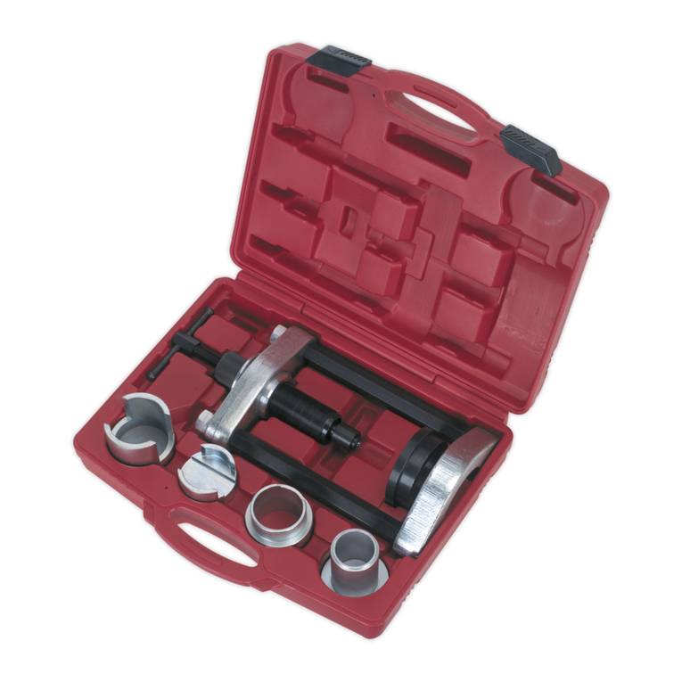
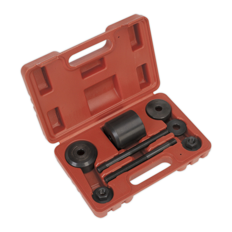
Suitable for the removal/installation of the front lower control arm bush on BMW 3 Series. Can be used in-situ without removing the arm from the
vehicle. When installing the new bushes, they must be held compressed while being pressed into the suspension control arm which this tool is
designed for. Supplied in carry-case.
APPLICATIONS: BMW 330xi: E90, E91, E92 3 Series (2005-2013)
Original Language Version VSE5586 Issue:1 - 11/10/13
INSTRUCTIONS FOR:
FRONT LOWER CONTROL ARM BUSH TOOL -
BMW 3 SERIES
MODEL No: VSE5586
Fig.2 Fig.3
3.1. REMOVING BUSH (Figs.2 & 3)
3.1.1. Place force screw (5) through adaptor plate (3).
3.1.2. Hold the adaptor adaptor sleeve (6) against the suspension arm and push the force screw through the centre of the bush.
3.1.3. Placetheopenfaceoftheadaptorcupplate(7)againsttheothersideofthebushandruntheforcescrewnut(5)upthethreaduntilnger
tight.
3.1.4. Apply a 15mm spanner to the head of the force screw and a 19mm socket to the force screw nut.
3.1.5. Tighten the force screw nut, forcing the bush from the suspension arm.
Fig.1
© Jack Sealey Limited
Item: Part No: Description:
1 VSE5568.01 Press Clamp Assembly
2 VSE5568.02 Force Screw Nut
3 VSE5568.03 Adaptor Plate
4 VSE5568.04 Adaptor Ring
5 VSE5568.05 Force Screw
6 VSE5568.06 Adaptor sleeve
7 VSE5568.07 Adaptor cup plate
NOTE: It is our policy to continually improve products and as such we reserve the right to alter data, specifications and component parts without prior notice.
IMPORTANT: No liability is accepted for incorrect use of this product.
WARRANTY: Guarantee is 12 months from purchase date, proof of which will be required for any claim.
INFORMATION: For a copy of our latest catalogue and promotions call us on 01284 757525 and leave your full name and address, including postcode.
Sole UK Distributor, Sealey Group,
Kempson Way, Suffolk Business Park,
Bury St. Edmunds, Suffolk,
IP32 7AR
01284 757500
01284 703534
sales@sealey.co.uk
www.sealey.co.uk
Web
email
Original Language Version
ALWAYS KEEP FORCE SCREW
WELL LUBRICATED. DO NOT USE AIR TOOLS.
Parts support is available for this product.
To obtain a parts list and diagram please log on to www.sealey.co.uk, email sales@sealey.co.uk or telephone 01284 757500
Force screw maximum load 150Nm. Exceeding this load will shorten the life of the force screw. The force screw is considered to be a
consumable item and is NOT covered under warranty.
Fig.4
Fig.6
Fig.5
Fig.7
3.2. INSTALLING REPLACEMENT BUSH
3.2.1. Place press clamp assembly (Fig.1.1) over the bush as in Fig.4. Place to one end of the bush rather than centrally.
3.2.2. Using a 10mm spanner, tighten the screw to close the gap in the bush.
3.2.3. Place the force screw (Fig.1.5) through the adaptor plate (Fig.1.3) and then place the adaptor plate on the adaptor sleeve.
3.2.4. Place the adaptor sleeve against the suspension arm with the force screw going through the housing.
3.2.5. Place the adaptor sleeve (Fig.1.4) against the outer face of the compressed bush and locate the bush against the other side of the
suspension arm. Put the adaptor cup plate (Fig.1.7) against the thrust washer and over the force screw. The arrangement is shown
in Fig.5
3.2.6. Runtheforcescrewnutupuntilngertight.Usingaspannerandsocketasin3.1.4.forcethebushintothesuspensionarmhousing
until the compressor is nearly touching the arm as in Fig.6.
3.2.7. At this point, remove the socket from the force screw nut and release the tension on the press clamp assembly. Remove the press clamp
assembly over the adaptor cup plate.
3.2.8. Replace the socket on the force screw nut and continue winding the bush into the housing until fully home as in Fig.7.
VSE5586 Issue:1 - 11/10/13
© Jack Sealey Limited
Environmental Protection.
Recycle unwanted materials instead of disposing of them as waste. All tools, accessories and packaging should be sorted, taken to a
recycling centre and disposed of in a manner which is compatible with the environment.