Latest products and information available at www.sealite.com
3
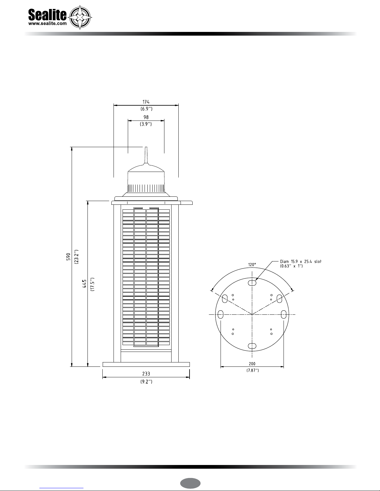
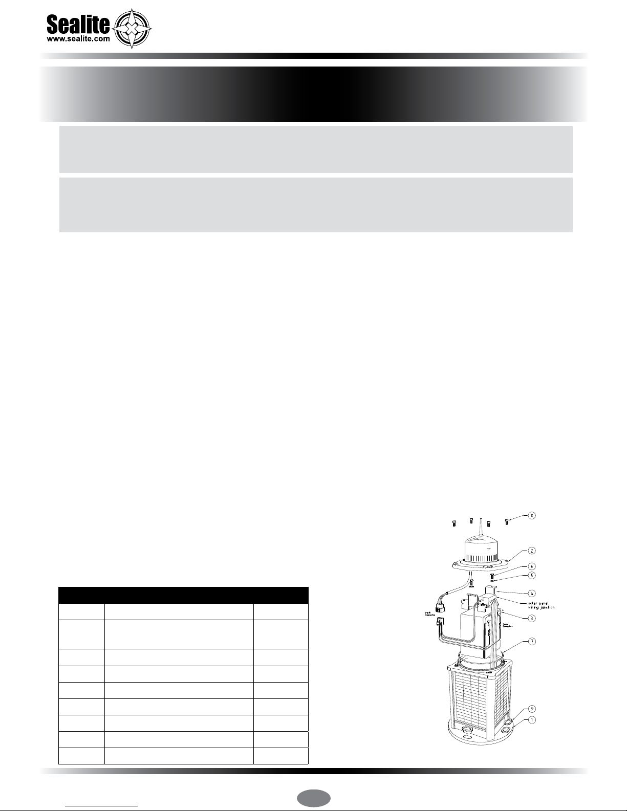
SL-C310, SL-C410 & SL-C415
3–5NM+ Marine Lanterns
Table of Contents
Introduction....................................................................................................... Page 4
Operating Principle .......................................................................................... Page 4
Technology........................................................................................................ Page 4
SL-C310, SL-C410 & SL-C415 Models ............................................................ Page 5
SL-C310 Model............................................................................................. Page 6
SL-C410 & SL-C415 Models......................................................................... Page 8
Installation ...................................................................................................... Page 10
Selecting an Intensity/Power Setting ........................................................... Page 11
Selecting a Flash Code .................................................................................. Page 12
Flash Codes .................................................................................................... Page 13
GPS Synchronisation..................................................................................... Page 19
Lantern Status ................................................................................................ Page 20
Optional IR Remote Control .......................................................................... Page 22
Sealite IR Controller / Universal Remote Compatibility.............................. Page 23
IR Controller Functions.................................................................................. Page 23
Test Mode / Congure................................................................................. Page 23
Normal Operation........................................................................................ Page 23
Read ........................................................................................................... Page 23
Flash Code.................................................................................................. Page 23
Flash Code Numbers.................................................................................. Page 22
Intensity....................................................................................................... Page 24
Battery Status ............................................................................................. Page 24
Operational Mode ....................................................................................... Page 24
Lux .............................................................................................................. Page 25
Error / Acknowledge Indication......................................................................... Page 26
Conguration Settings................................................................................. Page 26
Hibernation Mode (Advanced Users).......................................................... Page 27
Storage Mode (Advanced Users)................................................................ Page 29
Optional GSM Monitoring & Control System (SL-C410 & SL-C415) .......... Page 30
Maintenance & Servicing............................................................................... Page 31
Replacing the Battery.................................................................................. Page 31
Long Term Battery Storage ......................................................................... Page 31
Solar Panel Replacement ........................................................................... Page 32
How to Change the Regulator..................................................................... Page 33
Trouble Shooting ............................................................................................ Page 34
Sealite LED Light Warranty ........................................................................... Page 35