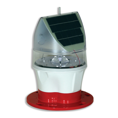
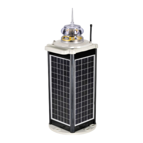
Sealite SLC500 Supplement

Version 4.0
SLC500 & SLC600
Solar Marine Lanterns
Installation & Service Manual


Latest products and information available at www.sealite.com
3
SLC500 & SLC600
Solar Marine Lanterns
Table of Contents
Introduction..........................................................................................Page 4
Operating Principle .............................................................................Page 4
Technology...........................................................................................Page 4
SLC500 Model......................................................................................Page 5
SLC500OptionalCongurations.................................................Page 8
SLC600 Model......................................................................................Page 9
SLC500OptionalCongurations...............................................Page 12
Installation..........................................................................................Page 13
RF Synchronisation (Comm-Sync) Option .....................................Page 15
GPS Synchronisation Option ...........................................................Page 16
Lantern Status ...................................................................................Page 17
Flash Codes .......................................................................................Page 19
Maintenance and Servicing ..............................................................Page 24
Trouble Shooting...............................................................................Page 25
Sealite Lantern Warranty ..................................................................Page 27
Version No. Description Date Approved
3.2 Update Manual August 2010 K. Paton
4.0 Update Spec Table & Remove SLC400 May 2012 J. Dore

Latest products and information available at www.sealite.com
4
SLC500 & SLC600
Solar Marine Lanterns
Introduction
Congratulations! By choosing to purchase a Sealite lantern you have become the owner of
one of the most advanced LED marine lanterns in the world.
Sealite Pty Ltd has been manufacturing lanterns for over 25 years, and particular care has been taken to
ensure your lantern gives years of service.
As a commitment to producing the highest quality products for our customers, Sealite has been independently
certiedascomplyingwiththerequirementsofISO9001:2008qualitymanagementsystem.
Sealite lanterns comply with requirements of the US Coast Guard in 33 CFR part 66 for Private Aids To
Navigation.
By taking a few moments to browse through this booklet, you will become familiar with the versatility of your
lantern, and be able to maximise its operating function.
Please remember to complete the Sealite warranty registration card accompanying your lantern.
Operating Principle
The solar module of the lantern converts sunlight to an electrical current that is used to charge the battery. The
battery provides power to operate the lantern at night.
Theasherunithasverylowcurrentrequirements.AmicroprocessordrivesanarrayofultrabrightLED’s
throughaDC/DCconverter,whichenablestheLED’stooperatewithinthemanufacturer’sspecications.The
battery is protected from over-charging within the circuit to ensure maximum battery life.
Ondarkness,themicroprocessorwillinitiateaprogramcheckandafterapproximately1minutebeginashing
to the set code
Technology
Sealite is the world’s fastest growing manufacturer of marine aids to navigation. We
employ leading mechanical, optical, hardware & software engineers to create innovative
products to service the needs of our customers worldwide, and offer the widest range of
solar-powered LED lanterns in the marketplace.
Electronics
Sealite employs leading in-house electronic engineers in the design and development of software and related
circuitry. All individual electronic components are sourced directly by Sealite procurement staff ensuring that
only the highest quality components are used in our products.
LED Technology
AllmarinelanternsusethelatestadvancementsinLED(LightEmittingDiode)technologyasalightsource.
ThemajoradvantageofLED’sovertraditionallightsourcesiswellestablishedinthattheytypicallyhavean
operational life in excess of 100,000 hours, resulting in substantial savings to maintenance and servicing
costs.
Precision Construction
Commitment to investing in the design and construction of injection-moulded parts including optic lenses, light
bases and a range of other components ensures that all Sealite products are of a consistent & superior quality.
Optical Performance
SealitemanufacturesarangeofmarineLEDlensesmouldedfrommulti-cavitydies.Complexshapessuchas
theSL70,BargeSafe™and16-segmentmulti-focuslensesareatestamenttothecompany’ssuperior
in-house lens manufacturing capabilities and outstanding optical performance.
Award-winning, Patented Technology
SeveralUnitedStatesandAustralianpatentregistrationsareheldonSealite’srangeofinnovativedesigns,
withotherregionalpatentspendinginCanada,UnitedKingdomandEurope.

Latest products and information available at www.sealite.com
5
SLC500 & SLC600
Solar Marine Lanterns
SLC500 Model
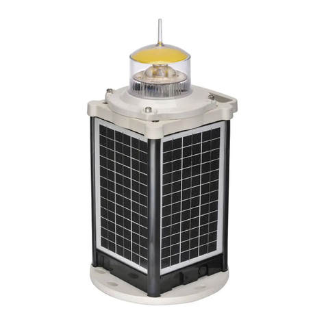
The SLC500 is a completely self-contained 5-7nm+ Solar LED Marine Lantern designed for a
range of low-maintenance applications.
The light boasts a large internal battery compartment, a multiple tiered SL125 light-head, and 4
premium-grade 10watt solar modules mounted to collect sunlight at all angles.
The SLC500 is moulded from UV-stabilised virgin polyethylene, providing enormous impact
and weather resistance, in addition to high visibility colours.
The tough polycarbonate lens is specically designed for use with LEDs, and incorporates an
environment-friendly spike - deterring unwelcome bird life. The lens design also ensures that
vessel operators clearly see the light from above, when passing the AtoN.
The user-friendly 2-piece design allows the lantern to be opened for convenient battery
inspection or replacement whilst the base remains xed to the supporting structure.
SL125-2 light-head
(72 ultra-high intensity
LEDs. IP68 rating)
High visibility
IALA colours for
daytime recognition
Rotationally-moulded,
UV-stabilised, virgin
polyethylene body
LED lens and Sealite’s
360 Omnidirectional
LED Reector
(US Pat. No. 6,667,582.
AU Pat. No. 778,918)
4 x 10watt
(40watts total)
multicrystalline solar
modules, ensuring
maximum light
collection to charge
the battery
Internal 55Ah battery

Latest products and information available at www.sealite.com
6
SLC500 & SLC600
Solar Marine Lanterns
•Specications subject to change or variation without notice
*Subject to standard terms and conditions
†Intensity setting subject to solar availability
SPECIFICATIONS •
Light Characteristics
Light Source SL125-2 (72 LED lantern as standard)
Available Colours Red, Green,White,Yellow, Blue
Maximum Available Intensity (cd)† Red - 383 Green - 317 White - 321 Yellow - 180
Visible Range (nm) 5–7+
Horizontal Output (degrees) 360
Vertical Divergence (degrees) 9
Reector Type Omnidirectional 360° LED Reector
(US Pat. No. 6,667,582.AU Pat. No. 778,918)
Available Flash Characteristics Up to 256 IALA recommended (user adjustable)
Intensity Adjustments Adjustable in 25% increments
LED Life Expectancy (hours) >100,000
Electrical Characteristics
Current Draw (mA) Refer to Sealite Power Calculator
Circuit Protection Integrated
Nominal Voltage (v) 12
Autonomy (days) >30 (14 hour darkness, 12.5% duty cycle)
Temperature Range -40 to 80°C
Solar Characteristics
Solar Module Type Multicrystalline
Output (watts) 40 (4 x 10watt)
Solar Module Efciency (%) 14
Charging Regulation Microprocessor controlled
Power Supply
Battery Type SLA (Sealed Lead Acid)
Battery Capacity (Ah) 55
Nominal Voltage (v) 12
Battery Service Life Average 5 years
Physical Characteristics
Body Material Rotationally-moulded UV-stabilised virgin polyethylene
Lens Material LEXAN® Polycarbonate – UV-stabilised
Lens Diameter (mm/inches) 150 / 57/8
Lens Design External optics with interior ute design
Mounting 4 x 11mm mounting holes
Height (mm/inches) 806 / 313/4
Width (mm/inches) 560 / 22
Mass (kg/lbs) 35 / 771/8
Product Life Expectancy Up to 12 years
Certications
CE EN61000-6-3:1997. EN61000-6-1:1997
Quality Assurance ISO9001:2008
Waterproof IP68 light-head
Intellectual Property
Patents US Pat. No. 6,667,582.AU Pat. No. 778,918
Trademarks SEALITE® is a registered trademark of Sealite Pty Ltd
Warranty * 3 years
Options Available • 200mm OD mounting plate
• GPS Synchronisation
• RF Synchronisation
• GSM Monitoring & Control System
• Radio Control System
• Note - remote monitoring/control will reduce visible range of lantern
due to increased power consumption

Latest products and information available at www.sealite.com
7
SLC500 & SLC600
Solar Marine Lanterns
Figure 1. SLC500

Latest products and information available at www.sealite.com
8
SLC500 & SLC600
Solar Marine Lanterns
SLC500 Optional Congurations
RF Synchronisation (SLC500-CS)
TheSLC500maybettedwithoptionalcommsyncRFmoduleforshortrangeashsynchronisation-
ideal for marina entrances and aquaculture applications.
GPS Synchronisation (SLC500-GPS)
Forashsynchronisationoflanternsinstalledoverlongerranges,aGPSmodulemaybetted.
Whenlanternsashinsynchronisationtheycanbeclearlydistinguishedfromothernavaidsand
confusing background lighting - ideal for rivers and channel marking.
GSM Monitoring & Control (SLC500-GSM)
TheSLC500mayalsobettedwithGSMremotemonitoringandcontrolcapabilities-enablingusers
to access real-time diagnostics data and change lantern settings via cell-phone or PC interface.
Radio Control (SLC500-RC)
RadiocontrolmaybettedtoSLC500modelenablinguserstoremotelymodifythesetupoftheir
lanternviahandheldradiocontroller(SL-RC-2.4).
Forexample,theoperatorcanremotelychangebetweendifferentcolouredLEDbanks(tochangethe
colourofthelight),turntheirlightsONandOFF,orchangetheashsetting.Perfectforremotetrafc
control and to designate an area of activity.

Latest products and information available at www.sealite.com
9
SLC500 & SLC600
Solar Marine Lanterns
SLC600 Model
The SLC600 is the world’s largest self-contained LED lantern, is a 6-9nm+ Solar LED Marine
Lantern designed for a range of low-maintenance applications. The large solar array make this
lantern perfect for low sunlight regions.
The light boasts a large internal battery compartment, a multiple tiered SL125 light-head, and 4
premium-grade 20watt solar modules mounted to collect sunlight at all angles.
The SLC600 is moulded from UV-stabilised virgin polyethylene, providing enormous impact
and weather resistance, in addition to high visibility colours.
The tough polycarbonate lens is specically designed for use with LEDs, and also enables
vessel operators clearly see the light from above, when passing the AtoN.
The user-friendly 2-piece design allows the lantern to be opened for convenient battery
inspection or replacement whilst the base remains xed to the supporting structure.
SL125-4 light-head
(144 ultra-high intensity
LEDs. IP68 rating)
Rotationally-moulded,
UV-stabilised, virgin
polyethylene body
High visibility
IALA colours for
daytime recognition
LED lens and Sealite’s
360 Omnidirectional
LED Reector
(US Pat. No. 6,667,582.
AU Pat. No. 778,918)
4 x 20watt
(80watts total)
multicrystalline solar
modules, ensuring
maximum light
collection to charge
the battery
Internal 100Ah battery
7-stage powder-coated
aluminium base with
handles for ease of
installation

Latest products and information available at www.sealite.com
10
SLC500 & SLC600
Solar Marine Lanterns
•Specications subject to change or variation without notice
*Subject to standard terms and conditions
†Intensity setting subject to solar availability
SPECIFICATIONS •
Light Characteristics
Light Source SL125-4 (144 LED lantern as standard)
Available Colours Red, Green,White,Yellow, Blue
Maximum Available Intensity (cd)† Red - 860 Green - 623 White - 602 Yellow - 363
Visible Range (nm) 6–9+
Horizontal Output (degrees) 360
Vertical Divergence (degrees) 5
Reector Type Omnidirectional 360° LED Reector
(US Pat. No. 6,667,582.AU Pat. No. 778,918)
Available Flash Characteristics Up to 256 IALA recommended (user adjustable)
Intensity Adjustments Adjustable in 25% increments
LED Life Expectancy (hours) >100,000
Electrical Characteristics
Current Draw (mA) Refer to Sealite Power Calculator
Circuit Protection Integrated
Nominal Voltage (v) 12
Autonomy (days) >20 (14 hour darkness, 12.5% duty cycle)
Temperature Range -40 to 80°C
Solar Characteristics
Solar Module Type Multicrystalline
Output (watts) 80 (4 x 20watt)
Solar Module Efciency (%) 14
Charging Regulation Microprocessor controlled
Power Supply
Battery Type SLA (Sealed Lead Acid)
Battery Capacity (Ah) 100
Nominal Voltage (v) 12
Battery Service Life Average 5 years
Physical Characteristics
Body Material Rotationally-moulded UV-stabilised virgin polyethylene
Lens Material LEXAN® Polycarbonate – UV-stabilised
Lens Diameter (mm/inches) 150 / 57/8
Lens Design External optics with interior ute design
Mounting 4 x 11mm mounting holes
Height (mm/inches) 945/ 371/4
Width (mm/inches) 665 / 261/4
Mass (kg/lbs) 60 / 1321/4
Product Life Expectancy Up to 12 years
Certications
CE EN61000-6-3:1997. EN61000-6-1:1997
Quality Assurance ISO9001:2008
Waterproof IP68 light-head
Intellectual Property
Patents US Pat. No. 6,667,582.AU Pat. No. 778,918
Trademarks SEALITE® is a registered trademark of Sealite Pty Ltd
Warranty * 3 years
Options Available • 200mm OD mounting plate
• GPS Synchronisation
• RF Synchronisation
• AIS Remote Monitoring
• GSM Monitoring & Control System
• Radio Control System
• Note - remote monitoring/control will reduce visible range of lantern
due to increased power consumption
• 9 degree lens

Latest products and information available at www.sealite.com
11
SLC500 & SLC600
Solar Marine Lanterns
Figure 2. SLC600

Latest products and information available at www.sealite.com
12
SLC500 & SLC600
Solar Marine Lanterns
SLC600 Optional Congurations
RF Synchronisation (SLC600-CS)
TheSLC600maybettedwithoptionalcommsyncRFmoduleforshortrangeashsynchronisation-
ideal for marina entrances and aquaculture applications.
GPS Synchronisation (SLC600-GPS)
Forashsynchronisationoflanternsinstalledoverlongerranges,aGPSmodulemaybetted.
Whenlanternsashinsynchronisationtheycanbeclearlydistinguishedfromothernavaidsand
confusing background lighting - ideal for rivers and channel marking.
GSM Monitoring & Control (SLC600-GSM)
TheSLC600mayalsobettedwithGSMremotemonitoringandcontrolcapabilities-enablingusers
to access real-time diagnostics data and change lantern settings via cell-phone or PC interface.
Radio Control (SLC600-RC)
RadiocontrolmaybettedtoSLC600modelenablinguserstoremotelymodifythesetupoftheir
lanternviahandheldradiocontroller(SL-RC-2.4).
Forexample,theoperatorcanremotelychangebetweendifferentcolouredLEDbanks(tochangethe
colourofthelight),turntheirlightsONandOFF,orchangetheashsetting.Perfectforremotetrafc
control and to designate an area of activity.

Latest products and information available at www.sealite.com
13
SLC500 & SLC600
Solar Marine Lanterns
Before activating the light, intensity and ash settings must be set.
Label “FRONT” indicates front of the lantern, where all operations must take place.
1. From the front of the lantern unscrew the four cap screws located at either side of the light-head
and remove.
2. Remove bung from base of light-head.
3. ThepowerandrangesettingsofthelanternareadjustedbysettingtheDIPswitchesinsidethe
lantern.Yourlanternisnormallysettomaximumrange(see‘SelectinganIntensitySetting’section
ofthismanual).
4. Setrotaryswitchestotherequiredashcode(see‘SelectingaFlashCode’sectionofthis
manual).
5. Replace bung, and place light-head back onto unit. Screw four cap screws up tight.
IMPORTANT: a sealed vent in the base allows air transfer without moisture intake and should
not be disturbed.
Lantern is activated by connecting +ve and -ve wires to +ve and -ve battery terminals.
1. From the front of the lantern, unscrew the four socket cap screws from the base of the solar unit,
and remove the body from the base plate.
2. Unscrew the 4 retaining knobs and remove the battery box lid.
3. Toactivatethelantern,connectthe“BatteryNegative(-)”wiretothenegativeterminal,and
the“BatteryPositive(+)”wiretothepositiveterminalofthebattery.Caremustbetakenwhen
replacing internal battery lid to ensure internal wiring is clear from sealed gasket.
4. Replacethebatteryboxlid,retthe4retainingknobsandtightensecurely.
5. Replace the lantern body onto the base plate ensuring that no wiring is protruding, and screw four
socket cap screws up tight.
6. Totestplacedarkcover(towelorjacket)ontopoflighttoactivatesensor,lightwillcomeon.
7. Ensurethattheunitisboltedtoaneven,atsurface.
Care must be taken to observe the polarity of each wire before they are connected.
To ensure waterproong of the unit, make sure that no wires are protruding and that
there is an even seal.
Installation

Latest products and information available at www.sealite.com
14
SLC500 & SLC600
Solar Marine Lanterns
Selecting an Intensity/Power Setting
Intensity/powersettingsonSealitelanternsoperateviaDIPswitches,locatedneartherotaryswitches
ontheasherunit.Thepulsesettingsmaybeusedtoreducethepowerconsumptionandintensity
of the lantern. Setting the lantern to 25% intensity will reduce the power consumption to 25% of the
normal 100% setting and the range by 25%. This setting may be used to adjust the current draw of the
light to local sunlight conditions.
Thefollowingdiagramsindicateintensity/powersettings:-
Selecting a Flash Code- Rotary Switches A and B
Alllanternshave2rotaryswitchesmarkedAandBontheasherunit.Turningthesmallarrowstothe
appropriate number or letter will set the code. The unit may take up to one minute to activate a new
ashcode.Acomprehensivelistofavailableashcodesislistedoninthe‘FlashCodes’sectionofthis
manual.
Example:
100%
1 2
ON
75%
1 2
ON
50%
1 2
ON
25%
1 2
ON
4
5
6
7
8
9
A
B
C
D
E
F
0
1
2
3
4
5
6
7
8
9
A
B
C
D
E
F
0
1
2
3
A
B
SWITCH FLASH CODE ON OFF
A B
A 0 FL 3 S 0.3 2.7

Latest products and information available at www.sealite.com
15
SLC500 & SLC600
Solar Marine Lanterns
RF Synchronisation (Comm-Sync) Option
Sealite’sinnovativeRFSynchronisationSystemisdesignedtoofferalow-costshortrangeash
synchronisation option for applications including rivers, estuaries, marina entrances, channel marking
and aquaculture.
RFSynchronisationmaybettedtotheSLC500andSLC600lanternsandbenetsvesseloperators
at night by illuminating the boundary or channel as a clear passage on entrance, as opposed to
indiscriminantashinglightswhichmayrenderthejudgmentofdistancedifcult.
Operating Principle
RFComm-SyncproductsarettedwithaninternalRFmodule,whichoperatesona2.4GHz
frequency and has an operational range of up to 1.4km between 2 lights.
Should more than 2 lanterns be required to be synchronised the range may be extended for longer
distances as each lantern transmits the data to all adjacent lanterns - causing them to fall into
synchronisation. The only limitation is that no lantern should be more than 1.4km from the next lantern
in the series.
RF Comm-Sync lanterns operate within a peer-to-peer network topology and therefore are not
dependent upon master/slave relationships. This means that lights remain synchronised without use of
master/slavecongurationsandeachlanterninthenetworksharesboththerolesofmasterandslave.
Usinginnovativesoftware,theadditionalpowerconsumptionisminimal,andinmostcongurations
the solar lantern requires only 1.5hrs of direct sunlight per day to retain full working autonomy.
Synchronisation is recommended for lanterns operating with up to 20% duty cycles and in
regions where typical solar irradiation averages 1.5Kwh per day. Flash characters exceeding
this may require lantern intensity adjustment.
Synchronisation is achieved via short-range RF communication between lanterns, and relies
on line-of-sight operation.
Setup
ToenableashsynchronisationofindependentRFComm-Synclanterns,setlanternstothesame
ashcharacteristic(see“SelectingaFlashCode”sectionofthismanual).
IMPORTANT: only lights set to the exact same ash pattern/code will ash in synchronisation.

Latest products and information available at www.sealite.com
16
SLC500 & SLC600
Solar Marine Lanterns
GPS Synchronisation Option
TheSLC500andSLC600lanternsmaybettedwithanoptionalinternallyintegratedGPSmodule
whichenablesashsynchronisationoflanternsinstalledoverlongerranges.
Whenlanternsashinsynchronisationtheycanbeclearlydistinguishedfromothernavaidsand
confusing background lighting. Users are able to mark a channel, port or river with independently
operatinglanternsthatallashinsynchronisationwhichimprovestheeffectivenessofmarkerlightsby
highlighting the outline each time the lanterns turn on.
No additional power supplies, aerials or control systems are required, and with its microprocessor-
basedsystem,theGPSoptionisspecicallydesignedtoprovidemaximumreliabilityandperformance
over a wide range of environmental conditions. The GPS board is a separate PCB mounted above the
standard lantern circuitry.
Operating Principle
Eachlightoperatesindependentlyandrequiresnooperatorintervention.Aminimumof3satellites
need to be in view for the built-in GPS receiver to collect time data. At dusk, the light sensor will turn
thelighton.Iftimedataisavailablethelightwillcomeonsynchronisedtoeveryotherlightwiththe
sameselectedashcode.
Synchronisation is achieved using an internal algorithm based on the highly accurate time base and
time data received from the satellites. The satellite data is provided from a number of earth stations
using atomic clocks as the time base. Continuous self-checking ensures that the light will continue to
run in synchronisation.
Light Activation
At power-up the microprocessor checks that the internal GPS module is programmed correctly and is
able to provide valid time base and time data.
Thelightthenchecksforday/night.Ifitisdaylighttheinternalmicroprocessorwillgotoidlemodeafter
approximately 10 seconds. This reduces the overall power consumption when the light is not required.
Once outside with a clear view of the sky, valid data should become available within 20 minutes.
Daylight Operation
During daylight hours the microprocessor is in idle mode to reduce power consumption. Time data
continues to be updated once per second. The microprocessor will automatically exit the idle mode as
soon as dark conditions are detected.
Dark Operation
Whendarkconditionsaredetectedthelight:
• Checksforvalidtimedataandisturnedonafteradelaybasedonthecurrenttimeandthelength
oftheselectedashcode;
• Ifvalidtimedataisnotdetectedthelightwillturnonafterapproximately10seconds.Thislightwill
not be synchronised.
• Ifthelightturnsonunsynchroniseditwillcontinuallycheckforvalidtimedata.Oncevaliddatais
found the light will automatically synchronise.
Setup
ToenableashsynchronisationofindependentRFComm-Synclanterns,setlanternstothesame
ashcharacteristic(see“SelectingaFlashCode”sectionofthismanual).
IMPORTANT: only lights set to the exact same ash pattern/code will ash in synchronisation.

Latest products and information available at www.sealite.com
17
SLC500 & SLC600
Solar Marine Lanterns
Lantern Status
STEADY LIGHT
LED Combinations
(Status Indicator LEDs ‘A’ in Fig.3.1.) Lantern Status Lantern Comment
YELLOW LED RED LED
Flashing ON/
OFF very quick 9
times per second
then 11 seconds
off
OFF Normal OFF Normal running condition in
daylight.
Flashing
constant OFF Normal ON Normal running condition.
Flashing ON/
OFF very quick 9
times per second
Fixed-on Low Battery
Voltage(<8v) OFF
Batteryisat.Batterymust
receive charge and light must
see daylight for at least 1
minute before resuming normal
operation.
Fixed-on OFF HighSolar
Voltage(>15.3v) ON
Battery is in state of very high
charge. Check regulator if
persists.
Flashing ON/
OFF 9 times per
second
Flashing ON/
OFF 1 time per
second
Highinternal
ambient
temperature
(>75°C)
ON
Internalambienttemperatureis
>75°C.Selectedlightintensity
is dropped by 25%. Will
resume normal operation when
temperature<75°C.
TwostatusLED’sonthemainprintedcircuitboard(positionAinimagebelow)providetheoperator
with an indication of the lantern status.
ThereisoneREDandoneYELLOWLEDthatindifferentcombinationsofON/OFF/FLASHINGwill
indicate the current operational status of the light,and vary depending on whether the lantern is set to
steady-on,oraashinglightcharacteristic.
TheseindicatorLED’scanbeviewedatthebaseofthelens.SeparateindicatorLEDsarelocatedon
thetopoftheGPScircuitboard(wheretted-seepositionB&Cofgure3.1.).
Figure 3.1.

Latest products and information available at www.sealite.com
18
SLC500 & SLC600
Solar Marine Lanterns
FLASHING LIGHT
LED Combinations
(Status Indicator LEDs ‘A’ in Fig.3.1.) Lantern Status Lantern Comment
YELLOW LED RED LED
A. Flashing ON/
OFF 1 time per
second
OFF
Normal and
synchronised
whenGPStted
ON
Normal running condition
synchronised to GPS. Will take
upto10minuteswhenrst
powered up. Condition only
active in darkness..
B. Flashing ON/
OFF very
quick constant
OFF Normal but not
synchronised ON
Normal running condition, but
light does not synchronise to
otherlights.GPSnotttedorno
time data received.
C. Flashing ON/
OFF very
quick 9 times
second then
11 seconds off
OFF Normal OFF Normal running condition in
daylight.
Flashing ON/
OFF very quick 9
times per second
Fixed-on Low Battery
Voltage(<8v) OFF
Batteryisat.Batterymust
receiver charge and light must
see daylight for at least 1
minute before resuming normal
operation.
Fixed-on OFF HighSolar
Voltage(>15.3v) ON
Battery is in state of very high
charge. Check regulator if
persists.
Flashing ON/
OFF 1 time per
second
Flashing ON/
OFF 1 time per
second
Highinternal
ambient
temperature
(>75°C)
ON
Internalambienttemperatureis
>75°C.Selectedlightintensity
is dropped by 25%. Will
resume normal operation when
temperature<75°C.
GPS BOARD (where tted)
LED Combinations Lantern Status Lantern Comment
YELLOW LED RED LED
(GPS Status Indicator LEDs ‘B’ in Fig.3.1.)
A. ON steady OFF Normal ON or
OFF GPS powered up.
(GPS Status Indicator LEDs ‘C’ in Fig.3.1.)
B. Flashing ON/
OFF very
quick constant
Flashing ON/
OFF very quick
constant faint
Normal ON GPS software running.
C. Flashes in
sequence with
red LED
Flashes in
sequence with
yellow LED
Off OFF/ON GPS software not operational.
NOTE
1. 1 second interval ashing Yellow LED indicates light is operating in synchronisation with the
optional tted GPS correctly.
2. If checking in daylight lantern must be covered to activate ash pattern.

Latest products and information available at www.sealite.com
19
SLC500 & SLC600
Solar Marine Lanterns
Flash Codes
SealiteLanternsmaybesettoanyof256IALArecommendedashsettingswhichareuser-adjustable
onsite without the need for external devices.
SEALITE® code reference is listed by number of ashes
For the latest version of this document visit www.sealite.com
Symbols
FL FlashfollowedbynumberEg.FL1S,oneasheverysecond
F Fixed
Q Quickash
VQ Veryquickash
OC Occulting;greaterperiodonthanoff
ISO Isophase;equalperiodonandoff
LFL Longashlong
MO Morsecode()containsletter
Forexample,VQ(6)+LFL10Smeans6veryquickashesfollowedbyalongash,duringa
10-second interval.
The amount of power your lantern draws through the night depends on the duty cycle, i.e. the amount of
time on as a proportion to the timing cycle. For example, 0.5 seconds on and 4.5 seconds off equals a
10% duty cycle.
Itisbesttooperateatthelowestdutycycleappropriatetotheactualneedsoftheapplication.
Recommended Rhythm for Flashing Light - IALA Regions A and B
MARK DESCRIPTION RHYTHM
Port Hand & Starboard Marks: Any,otherthanCompositeGroupFlashing(2+1)
Preferred Channel Starboard: CompositeGroupFlashing(2+1)
Preferred Channel Port: CompositeGroupFlashing(2+1)
North Cardinal Mark: Very quick or quick
East Cardinal Mark: Veryquick(3)every5secondsorquick(3)every10seconds
South Cardinal Mark: Veryquick(6)+longashevery10secondsorquick(6)+longashevery15seconds
West Cardinal Mark: Veryquick(9)every10secondsorquick(9)every15seconds
Isolated Danger Mark: Groupashing(2)
Safe Water Mark: Isophase,occulting,onelongashevery10secondsorMorseCode“A”
Special Marks: Any,otherthanthosedescribedforCardinal,IsolatedDangerorSafeWaterMarks

Latest products and information available at www.sealite.com.au
20
SWITCH FLASH CODE ON OFF
A B
0 0 F(Steadylight)
D 3 VQ 0.5 S 0.2 0.3
E3 VQ 0.6 S 0.2 0.4
F 3 VQ 0.6 S 0.3 0.3
7 3 Q 1 S 0.2 0.8
8 3 Q 1 S 0.3 0.7
9 3 Q 1 S 0.4 0.6
A 3 Q 1 S 0.5 0.5
8 4 Q 1 S 0.8 0.2
B 3 Q 1.2 S 0.3 0.9
9 4 Q 1.2 S 0.5 0.7
C 3 Q 1.2 S 0.6 0.6
F 4 FL 1.5 S 0.2 1.3
1 0 FL 1.5 S 0.3 1.2
0 5 FL 1.5 S 0.4 1.1
0 4 FL 1.5 S 0.5 1.0
2 0 FL 2 S 0.2 1.8
3 0 FL 2 S 0.3 1.7
4 0 FL 2 S 0.4 1.6
5 0 FL 2 S 0.5 1.5
6 0 FL 2 S 0.7 1.3
7 0 FL 2 S 0.8 1.2
1 2 ISO2S 1.0 1.0
8 0 FL 2.5 S 0.3 2.2
9 0 FL 2.5 S 0.5 2.0
D 6 FL 2.5 S 1.0 1.5
1 5 FL 3 S 0.2 2.8
A 0 FL 3 S 0.3 2.7
2 5 FL 3 S 0.4 2.6
B 0 FL 3 S 0.5 2.5
3 5 FL 3 S 0.6 2.4
C 0 FL 3 S 0.7 2.3
D 0 FL 3 S 1.0 2.0
2 2 ISO3S 1.5 1.5
5 4 OC 3 S 2.0 1.0
E2 OC 3 S 2.5 0.5
4 6 OC 3.5 S 2.5 1.0
4 5 FL 4 S 0.2 3.8
5 5 FL 4 S 0.3 3.7
E0 FL 4 S 0.4 3.6
F 0 FL 4 S 0.5 3.5
6 5 FL 4 S 0.6 3.4
0 1 FL 4 S 0.8 3.2
1 1 FL 4 S 1.0 3.0
2 1 FL 4 S 1.5 2.5
3 2 ISO4S 2.0 2.0
3 6 OC 4 S 2.5 1.5
F 2 OC 4 S 3.0 1.0
3 1 FL 4.3 S 1.3 3.0
8 5 FL 5 S 0.2 4.8
4 1 FL 5 S 0.3 4.7
5 1 FL 5 S 0.5 4.5
9 5 FL 5 S 0.9 4.1
6 1 FL 5 S 1.0 4.0
SWITCH FLASH CODE ON OFF
A B
7 1 FL 5 S 1.5 3.5
4 2 ISO5S 2.5 2.5
8 2 LFL 5 S 2.0 3.0
0 3 OC 5 S 3.0 2.0
1 3 OC 5 S 4.0 1.0
2 3 OC 5 S 4.5 0.5
C 6 FL 6 S 0.2 5.8
B 5 FL 6 S 0.3 5.7
C 5 FL 6 S 0.4 5.6
8 1 FL 6 S 0.5 5.5
9 1 FL 6 S 0.6 5.4
A 1 FL 6 S 1.0 5.0
7 5 FL 6 S 1.2 4.8
B 1 FL 6 S 1.5 4.5
5 2 ISO6S 3.0 3.0
9 2 LFL 6 S 2.0 4.0
6 4 OC 6 S 4.0 2.0
3 3 OC 6 S 4.5 1.5
4 3 OC 6 S 5.0 1.0
A 4 FL 7 S 1.0 6.0
9 6 FL 7 S 2.0 5.0
5 6 OC 7 S 4.5 2.5
D 5 FL 7.5 S 0.5 7.0
C 1 FL 7.5 S 0.8 6.7
E5 FL 8 S 0.5 7.5
B 4 FL 8 S 1.0 7.0
6 2 ISO8S 4.0 4.0
A 2 LFL 8 S 2.0 6.0
6 6 OC 8 S 5.0 3.0
B 2 LFL 8 S 3.0 5.0
F 5 FL 9 S 0.9 8.1
C 4 FL 9 S 1.0 8.0
7 6 OC 9 S 6.0 3.0
0 6 FL 10 S 0.2 9.8
1 6 FL 10 S 0.3 9.7
D 1 FL 10 S 0.5 9.5
2 6 FL 10 S 0.8 9.2
E1 FL 10 S 1.0 9.0
1 4 FL 10 S 1.5 8.5
C 2 LFL 10 S 2.0 8.0
D 2 LFL 10 S 3.0 7.0
7 2 ISO10S 5.0 5.0
2 4 LFL 10 S 4.0 6.0
8 6 OC 10 S 6.0 4.0
5 3 OC 10 S 7.0 3.0
6 3 OC 10 S 7.5 2.5
F 1 FL 12 S 1.2 10.8
D 4 FL 12 S 2.5 9.5
3 4 LFL 12 S 2.0 10.0
0 2 FL 15 S 1.0 14.0
4 4 LFL 15 S 4.0 11.0
7 4 OC 15 S 10 5.0
A 6 LFL 20 S 2.0 18.0
E4 FL 26 S 1.0 25.0
This manual suits for next models
1
Table of contents
Other Sealite Lantern manuals

Sealite
Sealite SL-125 Series Supplement

Sealite
Sealite SL-C510 Supplement

Sealite
Sealite iridium SL-510-SA Supplement

Sealite
Sealite SL-07LB Supplement

Sealite
Sealite SL-07 Series Supplement

Sealite
Sealite SL-15 User manual

Sealite
Sealite SL60 Supplement

Sealite
Sealite SL-70 Supplement

Sealite
Sealite SL-C510-AIS Supplement

Sealite
Sealite SLC310 Supplement