SeaPerch ROV Instructions for use
SeaPerch ROV Build v.2011-01AK Student Manual
i
SeaPerch
Remotely Operated Vehicle (ROV)
Construction Manual
Standard and Selected Optional
Assembly Procedures
January 2011
The SeaPerch educational program was created by Harry Bohm and Vickie
Jensen and published in their 1997 book "Build Your Own Underwater Robot
and Other Wet Projects." The initial curriculum was developed by the
Massachusetts Institute of Technology, and this version of the SeaPerch
Construction Manual was provided under the Office of Naval Research National
Naval Responsibility for Naval Engineering (NNRNE) Outreach
Version 2011-01AK
Student Manual

SeaPerch ROV Build v.2011-01AK Student Manual
i

SeaPerch ROV Build v.2011-01AK Student Manual
i
Table of Contents
Safety Overview…………………………………………………………………………….…i
Protective Eyewear
Materials Handling Safety
Safety While Using Hand Tools
Safety While Drilling
Safety While Soldering
Safety While Potting Motors for Thrusters
Safety with Electricity and Batteries
Unit 1 –Assembly of Subsystem One –The Vehicle Frame……………………1
Tools and Materials Needed
Time Needed to Complete Unit 1
Procedure 1.1 –Cut the Frame Parts
Procedure 1.2 –Drill the Drain Holes
Procedure 1.3 –Assemble the Vehicle Frame
Procedure1.4 –Assembly and Installation of the PVC Tube Floats
Procedure 1.5 –Attach the Thruster Mounts
Procedure 1.6 –Attach the Payload Net
Unit 2 –Assembly of Subsystem Two –The Thrusters…………………………11
Tools and Materials Needed
Time Needed to Complete Unit 2
Procedure 2.1 –Test the Motors and Mark their Terminals' Polarity
Procedure 2.2 –Seal the Motors So That Wax Cannot Get Inside
Procedure 2.3 –Drill Holes in the Thruster Housings
Procedure 2.4 –Connect the Tether Cable Wires to the Motors
Procedure 2.5 –Pot (Waterproof) the Motors with Wax
Procedure 2.5a –An Alternative to Potting Motors with Wax
Procedure 2.6 –Mount the Propellers on the Thruster Motors
Procedure 2.7 –Mount the Thrusters onto the Vehicle Frame
Procedure 2.8 –Waterproof and Secure the Tether Cable
Unit 3 –Assembly of Subsystem Three –The Control Box……………………25
Tools and Materials Needed
Time Needed to Complete Unit 3
SeaPerch ROV Electrical Circuit Diagram
Procedure 3.1 –Locate the Parts for the Control Box
Procedure 3.2 –Prepare the Control Box
Procedure 3.3 –Assemble the Power Cord
Procedure 3.4 –Wire the Vertical Thruster Control Switch
Procedure 3.5 –Wire the Horizontal Thruster Control Switches
Procedure 3.6 –Finish the Control Box
Table of Contents

SeaPerch ROV Build v.2011-01AK Student Manual
ii
Testing and Ballasting the ROV…………………………………………………..38
Initial Electrical Testing
Ballasting and Trimming the ROV
Using the SeaPerch ROV…………………………………………………………..41
Safety Precautions
Environments Suitable for Using a SeaPerch ROV
Driving the SeaPerch ROV
Post-Run Cleaning and Maintenance of the ROV System
Appendix I –Troubleshooting Your SeaPerch ROV…………………………..43
Appendix II –How to Solder Like a Pro………………………………………….45
Appendix III –Installing a DB-9 Connector on the Tether Cable……………51
Appendix IV –Installation of an Underwater Video Camera………………....55
SeaPerch ROV Build v.2011-01AK Student Manual
i
Safety During the Build
Protective Eyewear
Students, teachers, and classroom helpers should wear protective eyewear at all times when building
SeaPerch ROVs. Although some procedures do not usually involve significant eye hazards, the
students often work close to others, who at any time may be performing more potentially hazardous
steps. Activities such as soldering, cutting, drilling, applying adhesives, and potting thrusters can easily
cause materials or parts of broken tools to fly significant distances. Below are some examples:
Soldering: Solder contains rosin flux in its core to help clean the electrical connections, which
helps the solder to adhere to the metal properly. Small amounts of flux can occasionally pop
out of the melting solder and sometimes travel far enough to reach the eye of the person
soldering, or even someone nearby. Protective eyewear is essential for everyone in the area.
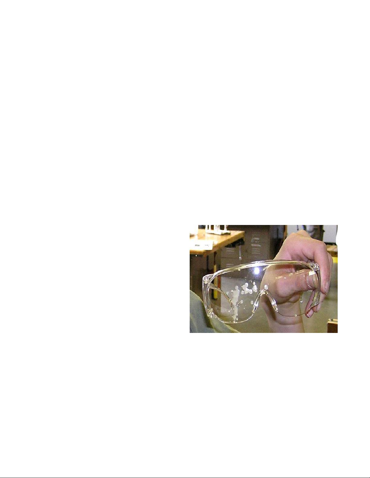
Potting Thrusters with Wax (if this method is used): Melting wax tends to stay in the
melting container or where it is poured. However, there is one step in the potting process that
can occasionally cause wax to fly a significant distance, often reaching a ceiling, wall, or floor,
and it therefore presents a risk for nearby eyes (as well as skin and clothing). This step is the
one in which the lid is pushed onto the thruster housing. If performed too quickly, it can result in
wax squirting out of the hole in the lid (where the wires pass through). Quick, hard pressing of
the lid is common, as students excitedly put the lid in place before the wax hardens or spills.
The picture above is an actual result of such an accident (held by a forever-committed safety-
glasses wearer).
Materials Handling Safety
Builders of SeaPerch ROVs should be made aware
of a few potential hazards related to some of the
materials used. The following activities require
careful handling of materials.
Soldering: Many common types of solder
contain lead, tin and sometimes other metals.
Solder should never be placed in one’s
mouth, and hands should always be washed
after working with solder. Breathing the
smoke from the melting flux (from inside the
solder) should be avoided.
Potting Wax (if used): Bowl ring wax is
made from “petrolatum” – basically the same type of material that, when more refined,
becomes common petroleum jelly. It is safe to handle when cooled, but quite sticky, and difficult
to remove if it solidifies on clothing. Hands should be washed with warm water and soap after
handling the wax. Obviously, it must not be ingested. Wearing eye protection, as noted earlier,
is essential.
Adhesives (if used): Adhesives, particularly two-part epoxy, “super glue” type adhesives, and
PVC primer and cement (some versions of SeaPerch ROVs don't use all of these types) can
present hazards to skin as well as eyes. Wearing eye protection and gloves is recommended
when working with any adhesives, and hands should always be washed after working with such
materials.

SeaPerch ROV Build v.2011-01AK Student Manual
ii
Protection of Our Environment: All waste or scrap materials from the SeaPerch ROV
construction process should be disposed of properly, in accordance with manufacturers’
recommendations and school policies. Recycling of usable excess materials and disassembled
vehicles is encouraged for environmental protection and cost avoidance considerations. Most
of the ROV components can be re-used in building future vehicles or as spare parts.
Safety While Using Hand Tools Using Hand Tools
Hand tools such as screwdrivers, pliers, and wire cutters can be used safely when operated as
intended. Examples of activities to avoid are below:
Screwdrivers: Screwdrivers should not be used to pry or make holes. Care should be
exercised while inserting or removing screws to avoid having the screwdriver tip slip off of the
screw head and poke into a body part or damage a table top. The size of the screwdriver tip
should be appropriate for the size of the screw.
Wire Cutters: Nothing should be cut with small wire cutters other than copper wire or plastic
tie wraps. Never cut pipe or metal fasteners, which could ruin the cutting edges. Be careful
when handling wire cutters to avoid being cut or poked by their sharp cutting edges or tips.
Needle-Nose Pliers: Small, thin, needle-nose pliers should be used only to help place wires
onto switch or motor terminals, as their jaws can bend or break if used for tightening tie wraps
or any prying activity. Large needle-nose pliers or standard club-nose pliers are better for
tightening tie wraps. Needle-nose pliers should also not be used for tightening the retaining
nuts on control box switches, as the jaws are not parallel like the edges of a nut, so they can
easily slip off. Use club-nose pliers or a small wrench instead to tighten the nuts on switches.
PVC Pipe Cutters: The blades on typical PVC pipe cutters can be damaged easily if used to
cut anything except PVC pipe, or if used incorrectly. When squeezing the tool to cut pipe, work
slowly so that the blade has time to move through the material. Do not twist the tool, and
always keep fingers away from the sharp blade. Store the tool in its closed position.
Safety While Drilling
Drilling is perhaps the most potentially hazardous activity involved in the SeaPerch project. Some
important safety considerations are as follows:
Get Permission to Use Power Tools: Always get the teacher’s permission and adult
supervision before using a drill or other power tool.
Installing and Removing Drill Bits: Install and remove drill bits from the chuck of a drill motor
or drill press manually, not by energizing the drill motor to spin the chuck closed. Make sure
that the bit is inserted straight into the chuck and that it is tight in the chuck before use; spin it
briefly to check before drilling.
Holding Objects Being Drilled: Never try to hold an object being drilled in your hand alone.
Instead, it should be always be either held in a vise (or clamp), firmly held down by hand onto a
solid surface (if that surface will not be subjected to possible damage during the drilling
process), or attached firmly to an object that can be safely held by hand. This keeps the
objectsteady, prevents it from spinning and hurting your hand if the drill bit should bind, and
keeps your fingers away from the bit while drilling. Never place a body part in the path of a drill
bit. Always think about what is behind the object being drilled (particularly body parts and

SeaPerch ROV Build v.2011-01AK Student Manual
iii
tabletops!). If using a drill press, make sure that the object is held firmly and fingers are not
near the drill bit.
Safety While Soldering (refer to Appendix II –How to Solder Like a Pro for tips)
Soldering Uses High Heat: All soldering involves a very hot soldering iron as well as
temporarily-hot electrical connections which take a few moments to cool after soldering. Do not
touch the tip area of a soldering iron, even when it appears to be off or unplugged, as it does
not look different when it is hot compared to when it is cold and it can remain hot for 10 minutes
or more after use. Connections should be allowed to cool after soldering before they are moved
or touched. As noted earlier, always wear eye protection, even when just in the same area as
someone who is soldering.
Keep the Soldering Iron in Its Holder When Not in Use: Great care should be taken to
place the soldering iron back into its holder whenever it is not in use for soldering. Never just
set it down on a tabletop, where it could burn anything it touches.
Safety While Potting Motors for Thrusters
SeaPerch ROV thrusters are assembled by potting small electric motors in wax. The following safety
issues should be reviewed with everyone involved in the potting process:
Melting Wax: The standard SeaPerch wax-melting approach is to warm “toilet bowl ring” wax
in a heated pot or a metal container placed in a hot water bath, usually employing an electric
hotplate to heat the water (and wax). It is important to always monitor the temperature of the
wax or use a water bath (and NOT let all of the water evaporate - keep adding water to
maintain it at about ½” to 1” deep). Otherwise, the wax can get EXTREMELY hot, even hot
enough to melt the plastic thruster housings. Fortunately, bowl ring wax has a relatively low
melting temperature, but it must still be heated to about 150 degrees Fahrenheit (F) for proper
pouring. Although its flash point is over 500 degrees F, manufacturers usually recommend not
exceeding 200 degrees F, so you should try to keep the wax at about 180 degrees F or below
(using a thermometer is best, as temperature control knob markings may be inaccurate). If the
wax is allowed to get too hot, skin burns are possible. In case of a burn, quickly rinse the area
with plenty of cold water and seek medical attention. Care should be taken to prevent getting
the hot wax onto skin or clothing. Wearing a protective smock or apron and gloves is
recommended. Pour the wax slowly and carefully to prevent spills and potential burns.
During the final step of thruster potting when the lid is placed onto the thruster housing, melted
wax can squirt out of the small hole in the lid where the wires pass through. If the lid is pressed
quickly into place, wax can even squirt as high as the ceiling or onto nearby walls and people.
Placing a paper towel over the lid and pressing slowly is recommended to avoid the wax-
squirting problem. Protect nearby walls and floor areas with paper or tarps. Obviously,
everyone in the area should be wearing eye protection.
Safety with Electricity and Batteries
The low-voltage (12 volts, direct current (DC)) battery power source used with SeaPerch ROVs is
relatively safe and well-proven in students’ hands. However, they should be cautioned about potential
problems from short-circuits as well as electrical safety issues in general.
Battery Short-Circuit Hazard: Although the battery can be used quite safely when it is
connected properly to the ROV, it can be damaged, cause wires to melt, or even start a fire if
its positive and negative terminals are connected directly together. That is called a “short

SeaPerch ROV Build v.2011-01AK Student Manual
iv
circuit,” and it will allow the battery to essentially discharge all of its stored energy at once.
Besides resulting in sparks when such an improper connection is made, the wire or metal
object shorting across the terminal will immediately become extremely hot and may even melt.
That could obviously cause burns or ignite an object in contact with the shorting material. Never
connect anything between the battery terminals except an appropriate electrical “load” such as
the ROV circuitry, through its fused power cord. Be careful to keep the battery terminals
covered or away from all wires and metal objects when not in use. Do not connect the ROV
circuitry or components to the battery until instructed to do so.
Avoid Creating Other Short Circuits During ROV Construction: When wiring circuits or
conducting tests, take care to avoid unintended connections or accidental short circuits. While
handling partially or fully completed circuits, ensure that wires do not move and touch together
where they should not. Always check the circuitry carefully and conduct the recommended tests
before connecting the battery.
General Electrical Safety: When working with electrical circuits with power applied, do not
allow any body parts to “become part of the circuit.” In other words, do not touch both the
positive and negative terminals of a battery with your hands or touch a battery terminal with one
hand and part of the circuitry with the other. Make sure that all switches are in their off positions
while connecting or disconnecting the battery, and connect just one power wire at a time.
SeaPerch
Remotely Operated Vehicle
Assembly of Subsystem One
The Vehicle Frame
January 2011
Version 2011-01AK

SeaPerch ROV Build v.2011-01AK Student Manual
2
Assembly of Subsystem One
The Vehicle Frame
Tools and Materials Needed
Procedure 1.1 - Cut the Frame Parts
Tools: Materials:
Ruler 5’ ½” Schedule 40 PVC pipe
Marker
PVC Pipe Cutter or Hacksaw
Construction Steps:
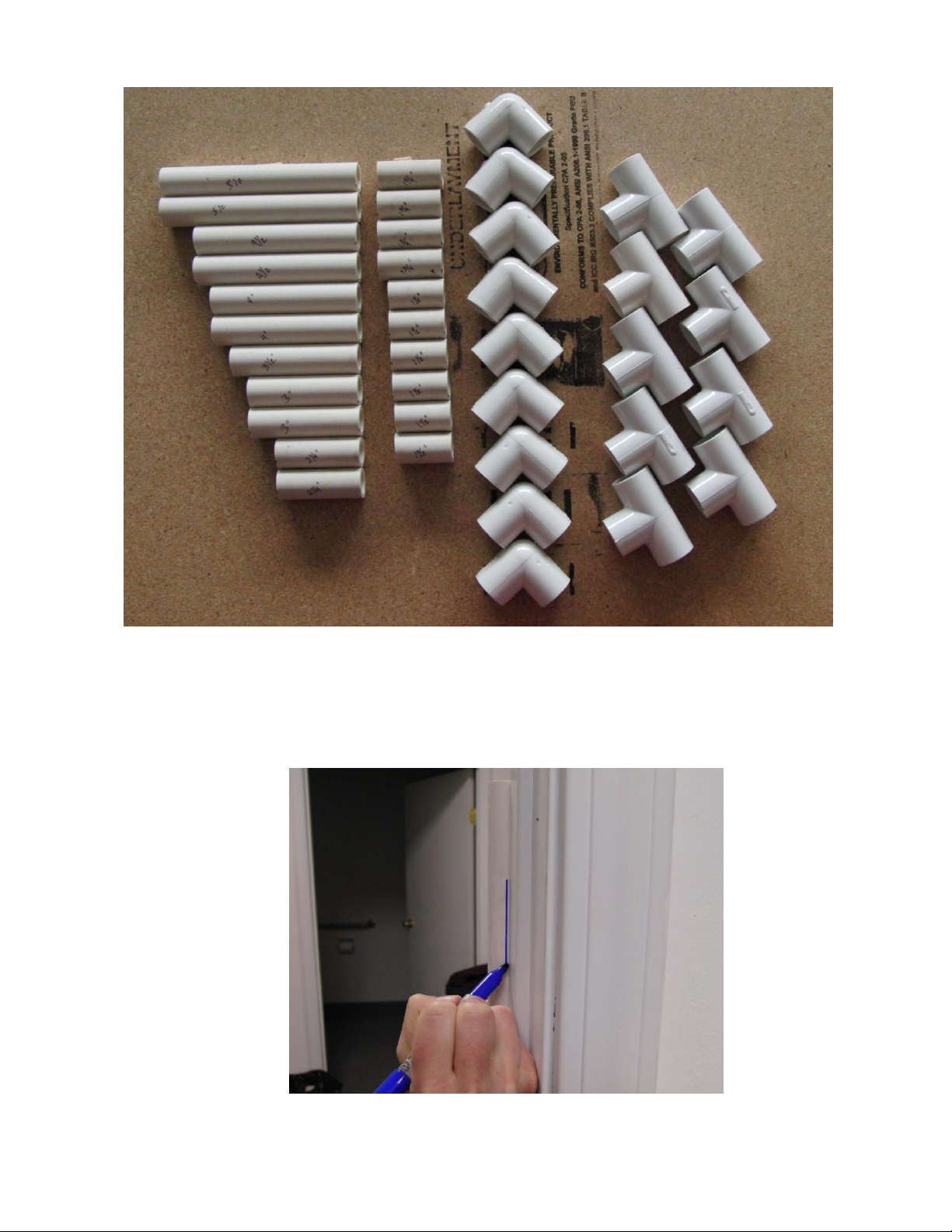
1. From a cleanly-cut end of a length of ½” pipe, measure and cut the pieces listed below. Cut the
longest pieces first, in case a mistake is made (smaller pieces may be cut from a longer piece
that is accidentally cut too short). You will find the old adage, “measure twice; cut once,” to be
the best advice here. Try to cut straight, so that the ends of each piece are square with the
sides, but don’t worry if they are not perfect.
Two pieces –5½” long Two pieces - 3” long
Two pieces –4½” long Two pieces –2¼” long
Two pieces –4” long Four pieces –1¾” long
One piece –3½” long Six pieces –1½” long
Write the length on each piece to keep track of cuts and to identify them later.
Tools
Materials
Eye Protection (Always Worn)
Ruler
Marker or Pencil
PVC Pipe Cutter (or Saw)
#2 Phillips Screwdriver
Flush Wire-Cutting Pliers
Drill (or Drill Press)
¼” Drill Bit
5/64” Drill Bit
Vise or Clamp
Pliers
Hack Saw
5’ (1.5 m) ½” PVC Pipe (Schedule 40 )
9½” PVC Elbows
9 ½” PVC Tees
28” (71 cm) 1” PVC Pipe (200 PSI Type)
4 1” PVC Pipe Caps
3 Thruster Mounts (1” Conduit Clamps)
6 #8 x ½” Phillips Sheet Metal Screws
6 #8 Washers (Optional)
1 12” x 6.5” (31 x 17 cm) Payload Net
1 Wire Coat Hanger
20 6” Tie Wraps (Zip Ties)
8 8” Tie Wraps (Zip Ties)
PVC Primer & Cement
Paper Towels & Rubbing Alcohol
SeaPerch ROV Build v.2011-01AK Student Manual
3
Take a piece of the 4½” pipe and place it in a piece of door frame molding. Draw a straight line on the
pipe parallel to its axis using the door frame as the straightedge. This line will be used when mounting
thruster brackets in Procedure 1.5. Repeat for the other 41/2” piece, and for the two 4” pieces of pipe.

SeaPerch ROV Build v.2011-01AK Student Manual
4
Procedure 1.2 - Drill the Drain Holes
Tools: Materials:
Hand drill or drill press 9 ½” PVC elbows
¼” drill bit
Vise or clamp
NOTE: Why are drain holes needed?
Drill Safety Reminders:
Drills can be dangerous pieces of equipment, but they are not difficult to operate properly. Always get your teacher’s
permission and supervision before using a drill or other power tool. Always wear safety glasses when building
your SeaPerch ROV (and when using any hand or power tool).
It is good practice to secure the object you are drilling in a vise or clamp before drilling. This keeps it steady, prevents
it from spinning and hurting your hand if the drill should bind, and keeps your fingers away from the sharp drill bit while
drilling. Be aware of what is behind the object you are drilling, to avoid extra holes in table tops or in other undesired
places!
If you do not have a vise or clamp available, push the elbow onto one end of a long (5” or more) piece of PVC pipe,
and hold the pipe while drilling the hole. DO NOT drill the elbow while holding it in your hand!
Construction Steps:
1. Inspect the PVC elbows to see if they have ¼” holes drilled in them (such as from a previous
use). If they all have ¼” holes, skip to Procedure 1.3.
2. Secure a PVC elbow in a vise or clamp.
3. Place the ¼" drill bit in the drill (or drill press), and drill a hole in the corner of the elbow. Drilling
from the interior of the elbow outward works best, as the bit can easily slip off of the rounded
exterior of the elbow.
4. Repeat Steps 2 and 3 for other PVC elbows that don’t have the ¼” holes.
Procedure 1.3 –Assemble the Vehicle Frame
Tools: Materials:
Rubber-faced hammer 23 Cut Pieces of pipe from Procedure 1.1
9 ½” PVC elbows from Procedure 1.2
9 ½” PVC Tees
Construction Steps
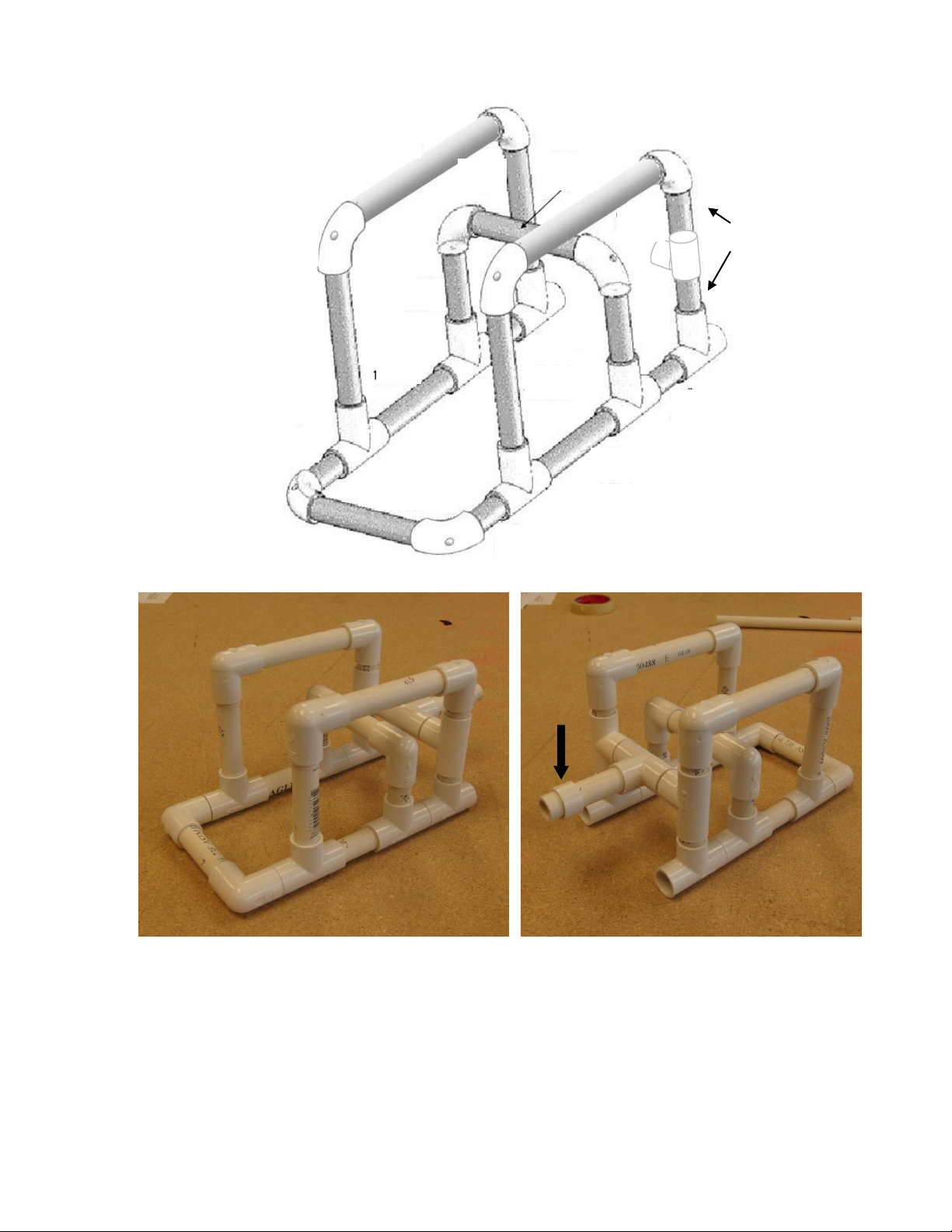
1. Assemble the frame using the PVC parts as shown below. Do not glue any of the connections.
Note that the two pieces of 1 ¾” pipe connected by a tee is shown only for the starboard
upright –an identical assembly would make up the port upright (not shown). The two tee’s, left
and right, will be connected by 2 pieces of 1 ½” PVC pipe with a tee in between them. Finally,
insert the 3 ½” piece of pipe into the tee and point it forward to act as a “nose”, able to pick up
objects. Refer to the two pictures to clarify what the final assembly should look like.
SeaPerch ROV Build v.2011-01AK Student Manual
5
5.5”
5.5
”
4.5”
4.5”
3”
3”
4”
4”
1.5”
1.5”
1.5”
2.25”
2.25
”
1.75”
Front
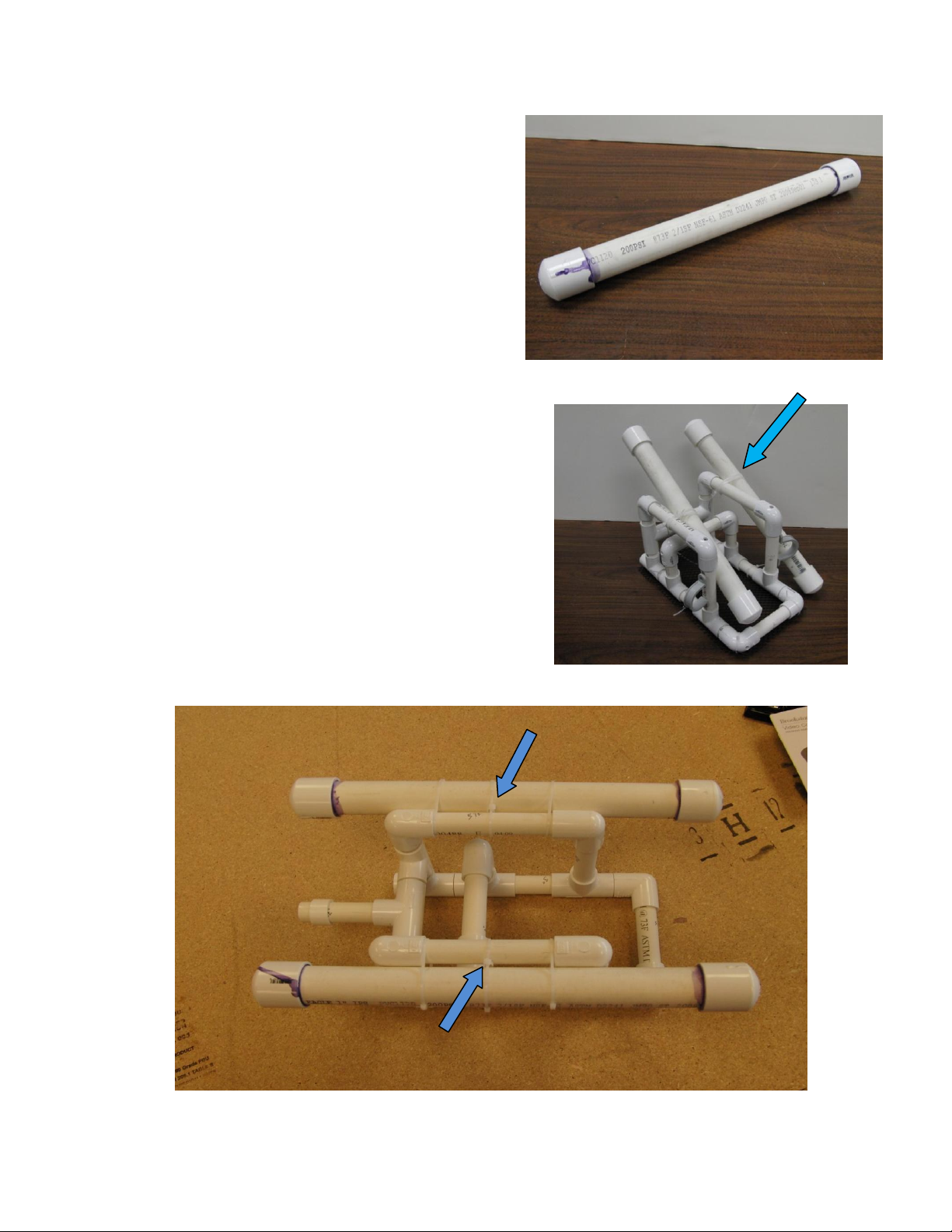
Note the PVC “collar” on the front nosepiece. This is added to help in firmly mounting the
camera on its shoe during camera installation, if used. It is made by snipping one leg off an
elbow as shown, carefully using the PVC pipe cutter.
Collar

SeaPerch ROV Build v.2011-01AK Student Manual
6
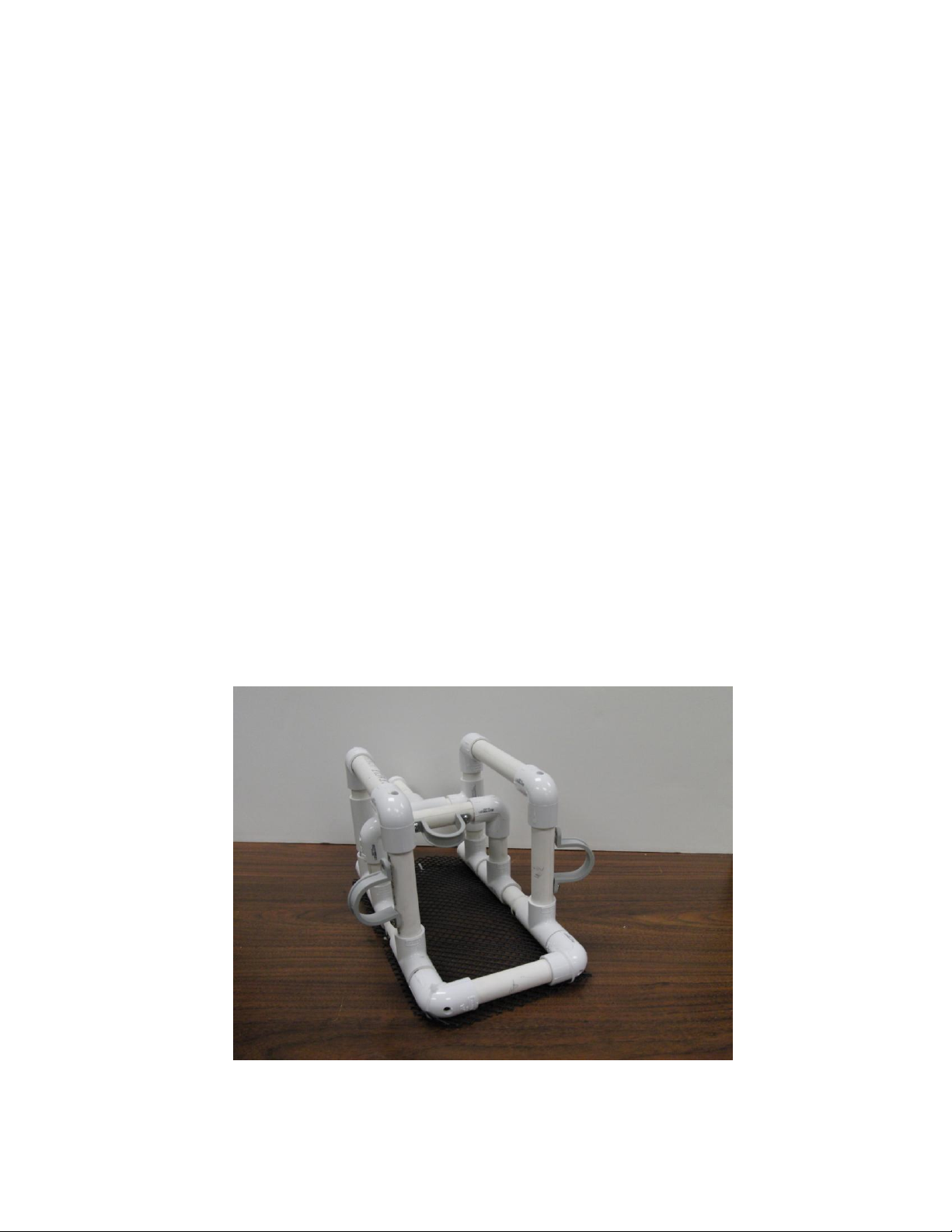
Slide the collar onto the nose. You will make final positioning adjustments when the camera is
installed (Appendix IV –Installation of an Underwater Video Monitor). Finally, firmly tap all of
the pieces of the frame together using a rubber-faced hammer, making sure that the frame is
squared up and parallel.
Procedure 1.4 –Assembly and Installation of the PVC Tube Floats
Tools: Materials:
PVC Pipe Cutter or Hacksaw 28” 1” PVC Pipe
Flush-Cut Wire Cutters 4 1” PVC End Caps
PVC Primer/Cement
8 8” Zip Ties
Paper Towels
Construction Steps:
1. Cut two pieces of 1” PVC Pipe, exactly 14” (35.5 cm) each. Measure and cut carefully so that
the completed flotation tubes will have the correct buoyancy.
2. Work in a WELL-VENTILATED area (outdoors or under a vent hood), with several layers of
paper towel or newspaper to protect the work surface and floor area from stains. Apply a VERY
SMALL amount of the purple PVC primer to each end of the two pipes, to about 1 inch from
each end, as indicated in the picture, being very careful not to drip the primer onto your clothes
or other objects that could get stained. Similarly, apply the primer around the inside surface of
each of the four end caps. The primer cleans the PVC and softens it in preparation for
cementing the pieces together. Immediately
close the primer container.
3. Again, in a well-ventilated area and over the
protected floor or table top, quickly apply a thin
layer of PVC cement all of the way around one
end of one of the 1” PVC pipes and inside one
of the end caps. Glue just one end cap at a
time. Immediately after applying the adhesive,
push the end cap onto the pipe, twist it about a
quarter turn, and hold it firmly in place for a few
seconds. Put the cap back on the adhesive
container as soon as possible, to minimize the
SeaPerch ROV Build v.2011-01AK Student Manual
7
escape of vapors and to prevent the contents from drying out. Remove any excess glue from
the outside of the pipe using a paper towel;
discard the towel.
4. Repeat step 3 for the other end of the pipe, and
then for each end of the other pipe, one end at a
time. After all four end caps have been glued
onto the pipes, discard the paper that was used
to protect the table top and floor.
5. Position the float tubes so that they are parallel
to the top frame members. Attach the floats by
using three 8” zip ties on both port and
starboard sides and wrap them around the float
and the frame piece. Leave the ties a little loose for now.
6. Move the float so that it is at an angle to the frame
pipe as shown. Slide all of the zip ties towards the
cross angle between the two pipes, as shown.
Tighten the ties using a pair of blunt-nose pliers.
7. Move the float so that it is parallel to the frame pipe
and move the ties back along the length of the float.
Then frap the zip ties by wrapping an 8” tie around
each existing tie between the float and the frame
pipe. Tighten as much as possible using pliers, and
trim all of the tails using the flush-cut cutters.
SeaPerch ROV Build v.2011-01AK Student Manual
8
Procedure 1.5 –Attach the Thruster Mounts
Tools: Materials:
Drill Vehicle Frame
5/64” Drill Bit 3 1” Plastic Pipe Strap
#2 Phillips Screwdriver 6 #8 x ½” Phillips Head Sheet Metal Screws
Thruster Mounting Tips:
For now, don’t worry about the direction in which the three thruster mounts are positioned. Since you do not glue the
joints in the PVC frame, you can change the angles of the mounts later by simply turning the pipe in its joints using a
pair of pliers. It is easier to drill and attach the thruster mounts on the back (outside) of the frame… we’ll adjust them
later.
This is a good time to think about how the angle of the thrusters affects the performance of the ROV. What angles will
get you the best forward and backward thrust? What angles will get you the best turning ability? What is the best
compromise for your mission needs?
Construction Steps:
1. Hold a thruster mount against the frame, positioning the holes on the lines you drew in
Procedure 1.1 in the three locations shown in the picture, and using a marker or pencil, mark
the vehicle frame through the holes in the thruster mounts. Centering the mounts between the
joints on the pipe is more important than placing them at a specific angle around the pipe (they
can easily be turned later).
2. Using the 5/64” drill bit, drill holes through the six marks on the frame.
3. Using #8 screws and washers (washers are optional if the heads on your screws are large
enough that they will not pass through the holes in the thruster mounts, and if the thruster
mounts are metal or hard plastic). LOOSELY attach the thruster mounts to the frame. DO NOT
over-tighten the screws and strip the holes in the PVC!! You will be removing the mounts
later anyway to install the thrusters in them.
SeaPerch ROV Build v.2011-01AK Student Manual
9
Procedure 1.6 –Attach the Payload Net to the Frame
Tools: Materials:
Scissors Assembled Vehicle Frame
Pliers 12” x 7” Polypropylene Netting
Flush-cut Wire Cutters Wire Coat Hanger
Hack Saw or Tin Snips 12 6” Zip Ties
Drill
3/32” Drill Bit
ROV Painting Tip:
If you wish to paint your vehicle’s frame, do so before attaching the nets, and be sure to use waterproof paint. Also
confirm that all vehicle pipe sections and fittings are as tight as possible and that the frame is squared-up before
painting, as the parts may be difficult to move after the paint has dried.
Construction Steps:
1. Check the frame to ensure that all pipe sections and fittings are pressed tightly together.
2. Place the payload net underneath the vehicle
frame and trim it to size with scissors if
necessary. Leave as little net as possible
extending beyond the edges of the frame.
The net is often a bit curved from being
stored on a roll; make sure that it is placed
under the frame with the concave side facing
toward the frame.
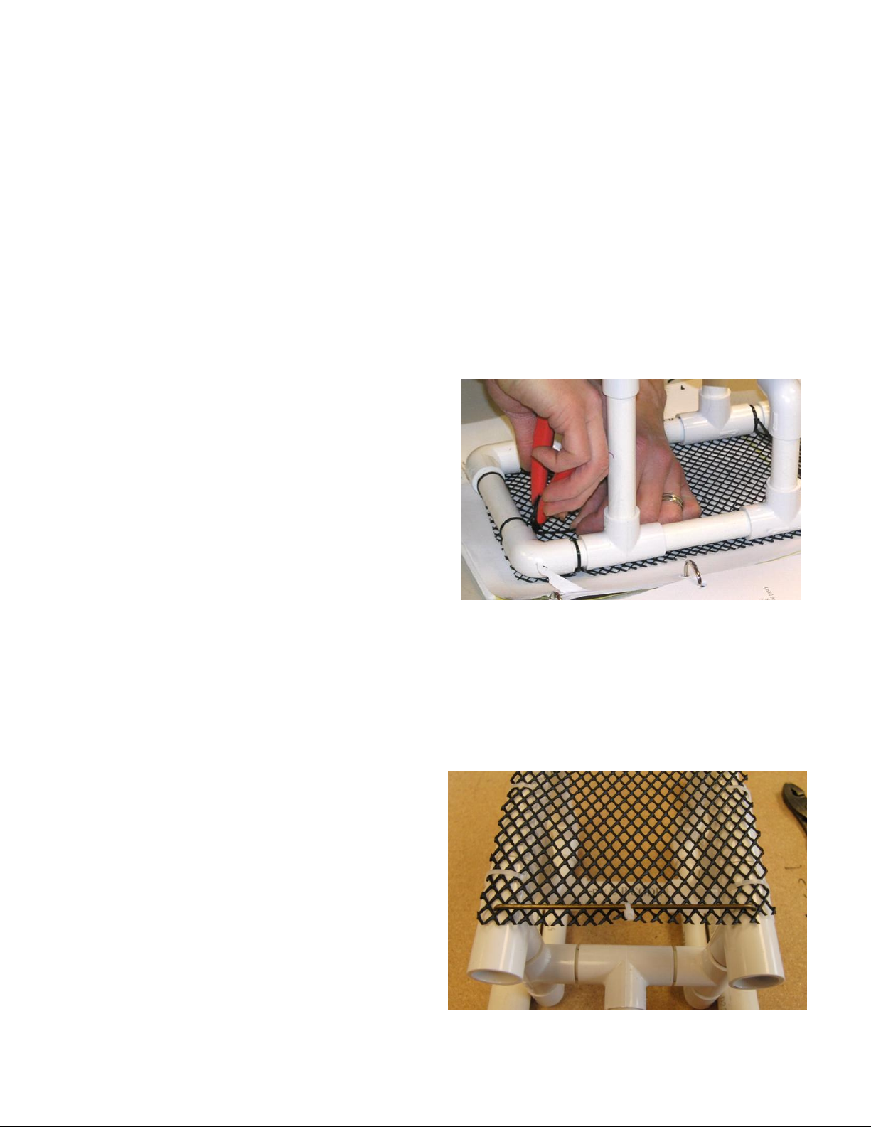
3. Attach the payload net to the frame using
about eight 6” tie wraps (also known as
“cable ties” or “zip ties”). Pull them tight using pliers (NOT thin needle-nose pliers, as their tips
may bend or even break when twisted!). Make sure the net is tight and flat on the bottom of the
ROV, and that the front edge of the net is even with the front vertical pipes, NOT with the
front of the PVC Tees.
4. Trim off the ends of the tie wraps using flush wire-cutting pliers (not scissors, which can leave
very sharp ends that can easily scratch skin) as shown.
5. Using the Flush-cut nippers, trim the ends of the payload net so that it is square with the bottom
footprint of the frame, as shown.
6. Coat hangers usually come in two versions:
a “heavy” one (0.105” dia) and a “light” one
(0.075” dia). You want to use the heavy one
for your stiffener. Turn your ROV upside
down and, using a 3/32” drill bit, drill a hole
through the center of each front frame tee.
7. Cut your wire coat hanger to 9” long and
bend up ~1¾” of wire at each end to 90º.

SeaPerch ROV Build v.2011-01AK Student Manual
10
8. With a little wiggling and maybe the light tap of a hammer, the upturned ends of the wire
stiffener can be inserted and set into the holes, as shown. Turn your ROV back over and attach
the payload net to the stiffener with one or two tie wraps. Trim the tails from the ends of the tie
wraps.
Congratulations! You have completed the frame for your SeaPerch ROV!
SeaPerch ROV Build v.2011-01AK Student Manual
11
SeaPerch
Remotely Operated Vehicle
Assembly of Subsystem Two
The Thrusters
January 2011
Version 2011-01AK

SeaPerch ROV Build v.2011-01AK Student Manual
12
Tools and Materials Needed
Tools: Materials:
Eye Protection 40’ Tether Cable (CAT 5 or 5e)
Drill 3 Plastic Vials
5/64” Drill Bit 3 12VDC Motors
Small Electric Hotplate 3 Propellers
Metal Cup for Wax 3 1/8” x ½” Roll Pins
Pliers 3/4 Wax Bowl Ring
Wire Stripper 16-24 ga. 1” Butyl Rubber Tape
Flush-cut Wire Cutters 24” #22 Stranded Red Hook-up Wire
Locking Long-Nose Pliers 24” #22 Stranded Black Hook-up Wire
Soldering Iron and Rosin Core Solder 1 12VDC Battery
#2 Phillips Screwdriver 12 Zip Ties
3/32” Drill Bit
Alternative Potting Procedure
Wooden Stirrer Marine Potting Epoxy
Procedure 2.1 - Test the Motors and Mark the Terminal Polarity
Tools: Materials:
Marker 3 12VDC Motors
Wire Stripper 2 24” #22 Hook-up Wire, One Red & One Black
12 VDC Battery
Electrical Tape
WARNING - TO AVOID ELECTRIC SHOCK AND POTENTIAL BURNS:
- DO NOT touch exposed wires when making connections to battery terminals.
- DO NOT touch the battery terminals with ANY metal object, especially tools!
- DO NOT CONNECT WIRE OR METAL FROM ONE BATTERY TERMINAL TO THE OTHER!
Construction Steps:
1. Gather the red and black 24” hook-up wires to use as a pair of test wires (these are temporary;
they will be used later to make the power cord and your control box in Unit 3) and some
electrical tape.
2. Strip about 3/8” (1 cm) of insulation from both ends of the black hook-up wire, without cutting
the copper strands inside. Use the 22 ga. notch on the wire stripper.
3. Repeat Step 2 with the red hook-up wire.
4. If the motors have any wire leads soldered to their terminals, clip the wires off and use a de-
soldering tool (such as a vacuum solder remover or a solder-wicking braid) to remove the wires
and any excess solder from the terminals.
5. Cut about 1” (2.5 cm) of electrical tape, and place it temporarily onto the shaft of each motor,
wrapping it around the shaft with the end extending out like a flag, to help you see the motor’s
spin direction when it is energized.
6. Connect the red and black wires to the two terminals on one of the motors (twist them through
or around the terminals) and hold them temporarily in place with small pieces of electrical tape.
Other manuals for ROV
1
Table of contents
Other SeaPerch Educational Equipment manuals


Popular Educational Equipment manuals by other brands


Quanser
Quanser 6 DOF Hexapod Laboratory guide

Surefire
Surefire Flying Model Rocket Kit How to use

ACROME
ACROME myCONTROL STEWART PRO user manual

SmartMan
SmartMan Baby Manikin manual

Nasco
Nasco Life/form LF03840U instruction manual

Pitsco Education
Pitsco Education BUILDERSPACES SPACEPORT Assembly instructions