Sears CRAFTSMAN 944.627594 User manual

Caution:
Read and follow
all Safety Rules
and Instructions
Before Operating
This Equipment
MODEL NO.
944.627594
OWNER’S
MANUAL
• Assembly
• Operation
• Customer Responsibilities
• Service and Adjustments
• Repair Parts
9.0 HP
21 INCH TINE WIDTH
REAR TINE TILLER WITH
COUNTER ROTATING TINES
Sears Canada, Inc., Toronto, Ontario M5B 2B8

2
• Do not run the engine indoors; exhaust fumes are
dangerous.
• Never operate the tiller without proper guards, plates, or
other safety protective devices in place.
• Keep children and pets away.
• Do not overload the machine capacity by attempting to
till too deep at too fast a rate.
• Never operate the machine at high speeds on slippery
surfaces. Look behind and use care when backing.
• Never allow bystanders near the unit.
• Use only attachments and accessories approved by the
manufacturer of the tiller.
• Never operate the tiller without good visibility or light.
• Be careful when tilling in hard ground. The tines may
catch in the ground and propel the tiller forward. If this
occurs, let go of the handlebars and do not restrain the
machine.
MAINTENANCE AND STORAGE
• Keep machine, attachments, and accessories in safe
working condition.
• Check shear pins, engine mounting bolts, and other
bolts at frequent intervals for proper tightness to be sure
the equipment is in safe working condition.
• Never store the machine with fuel in the fuel tank inside
a building where ignition sources are present, such as
hot water and space heaters, clothes dryers, and the
like. Allow the engine to cool before storing in any
enclosure.
• Always refer to the operator’s guide instructions for
important details if the tiller is to be stored for an
extended period.
- IMPORTANT -
CAUTIONS, IMPORTANTS, AND NOTES ARE A MEANS
OF ATTRACTING ATTENTION TO IMPORTANT OR
CRITICAL INFORMATION IN THIS MANUAL.
IMPORTANT: USED TO ALERT YOU THAT THERE IS A
POSSIBILITY OF DAMAGING THIS EQUIPMENT.
NOTE: Gives essential information that will aid you to better
understand, incorporate, or execute a particular set of
instructions.
Look for this symbol to point out impor-
tant safety precautions. It means
CAUTION!!! BECOME ALERT!!! YOUR
SAFETY IS INVOLVED.
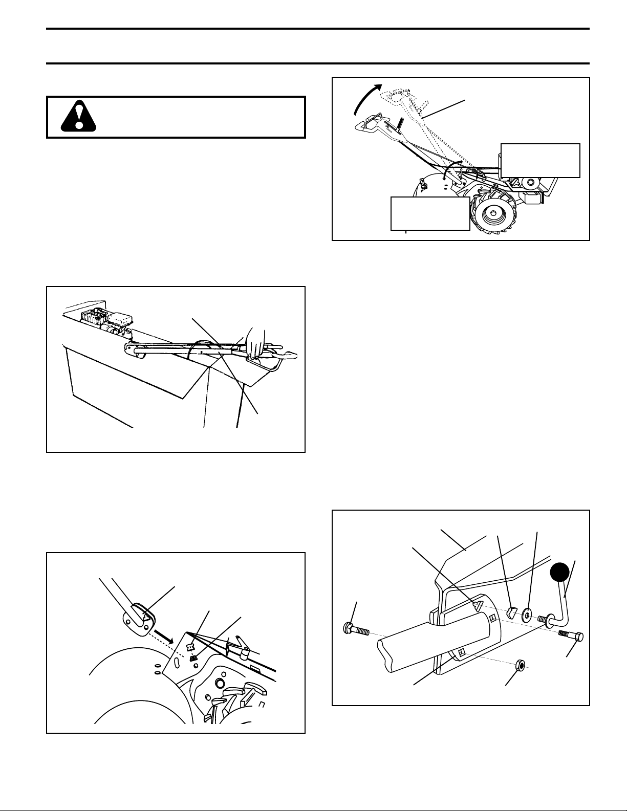
CAUTION: Always disconnect spark
plug wire and place wire where it cannot
contact spark plug in order to prevent
accidental starting when setting up,
transporting, adjusting or making re-
pairs.
SAFETY RULES
SAFE OPERATION PRACTICES FOR WALK-BEHIND POWERED ROTARY TILLERS
TRAINING
• Read the Owner’s Manual carefully. Be thoroughly
familiar with the controls and the proper use of the
equipment. Know how to stop the unit and disengage the
controls quickly.
• Never allow children to operate the equipment. Never
allow adults to operate the equipment without proper
instruction.
• Keep the area of operation clear of all persons, particu-
larly small children, and pets.
PREPARATION
• Thoroughly inspect the area where the equipment is to
be used and remove all foreign objects.
• Disengage all clutches and shift into neutral before
starting the engine (motor).
• Do not operate the equipment without wearing adequate
outer garments. Wear footwear that will improve footing
on slippery surfaces.
• Handle fuel with care; it is highly flammable.
• Use an approved fuel container.
• Never add fuel to a running engine or hot engine.
• Fill fuel tank outdoors with extreme care. Never fill fuel
tank indoors.
• Replace gasoline cap securely and clean up spilled fuel
before restarting.
• Use extension cords and receptacles as specified by
the manufacturer for all units with electric drive motors
or electric starting motors.
• Never attempt to make any adjustments while the
engine (motor) is running (except where specifically
recommended by manufacturer).
OPERATION
• Do not put hands or feet near or under rotating parts.
• Exercise extreme caution when operating on or crossing
gravel drives, walks, or roads. Stay alert for hidden
hazards or traffic. Do not carry passengers.
• After striking a foreign object, stop the engine (motor),
remove the wire from the spark plug, thoroughly inspect
the tiller for any damage, and repair the damage before
restarting and operating the tiller.
• Exercise caution to avoid slipping or falling.
• If the unit should start to vibrate abnormally, stop the
engine (motor) and check immediately for the cause.
Vibration is generally a warning of trouble.
• Stop the engine (motor) when leaving the operating
position.
• Take all possible precautions when leaving the machine
unattended. Disengage the tines, shift into neutral, and
stop the engine.
• Before cleaning, repairing, or inspecting, shut off the
engine and make certain all moving parts have stopped.
Disconnect the spark plug wire, and keep the wire away
from the plug to prevent accidental starting. Disconnect
the cord on electric motors.

3
PRODUCT SPECIFICATIONS
GASOLINE CAPACITY: 4 Quarts (3.8L)
Unleaded Regular
OIL (API-SF/SG/SH): SAE 30 (Above 32°F/0°C)
(Capacity: 44 oz./1.3L) SAE 5w-30 (Below 32°F/0°C)
SPARK PLUG : Champion
(GAP: .030"/0.76mm) J19LM
TABLE OF CONTENTS
SAFETY RULES ......................................................... 2
CUSTOMER RESPONSIBILITIES .................... 3,12-14
PRODUCT SPECIFICATIONS ..................................... 3
WARRANTY ................................................................ 3
ASSEMBLY .............................................................. 4-6
OPERATION ........................................................... 7-11
MAINTENANCE SCHEDULE ..................................... 12
SERVICE & ADJUSTMENTS ............................... 14-17
STORAGE ................................................................. 18
TROUBLESHOOTING ............................................... 19
REPAIR PARTS-TILLER ...................................... 20-26
REPAIR PARTS-ENGINE ..................................... 27-30
PARTS ORDER/SERVICE ..................... BACK COVER
CUSTOMER RESPONSIBILITIES
• Read and observe the safety rules.
• Follow a regular schedule in maintaining, caring for and
using your tiller.
• Follow the instructions under the “Customer Responsi-
bilities” and “Storage” sections of this Owner’s Manual.
CONGRATULATIONS on your purchase of a Sears Tiller. It
has been designed, engineered and manufactured to give
you the best possible dependability and performance.
Should you experience any problems you cannot easily
remedy, please contact your nearest authorized service
center/department. They have competent, well-trained
technicians and the proper tools to service or repair this unit.
Please read and retain this manual. The instructions will
enable you to assemble and maintain your tiller properly.
Always observe the “SAFETY RULES”.
IMPORTANT: THIS UNIT IS EQUIPPED WITH AN
INTERNAL COMBUSTION ENGINE AND SHOULD NOT
BE USED ON OR NEAR ANY UNIMPROVED FOREST-
COVERED, BRUSH-COVERED OR GRASS COVERED
LAND UNLESS THE ENGINE’S EXHAUST SYSTEM IS
EQUIPPED WITH A SPARK ARRESTER MEETING
APPLICABLE LOCAL OR STATE LAWS (IF ANY). IF A
SPARK ARRESTER IS USED, IT SHOULD BE MAINTAINED
IN EFFECTIVE WORKING ORDER BY THE OPERATOR.
IN THE STATE OF CALIFORNIA THE ABOVE IS REQUIRED
BY LAW (SECTION 4442 OF THE CALIFORNIA PUBLIC
RESOURCES CODE). OTHER STATES MAY HAVE
SIMILAR LAWS. FEDERAL LAWS APPLY ON FEDERAL
LANDS. SEE YOUR SEARS AUTHORIZED SERVICE
CENTER/DEPARTMENT FOR SPARK ARRESTER. REFER
TO THE REPAIR PARTS SECTION OF THIS MANUAL FOR
PART NUMBER.
LIMITED TWO (2) YEAR WARRANTY ON CRAFTSMAN TILLER
For Two (2) years from date of purchase Sears Canada, Inc. will repair or replace at Sears option free of charge parts which
are defective as a result of material or workmanship.
COMMERCIAL OR RENTAL USE:
Warranty on Tiller will be thirty (30) days from date of purchase if used for commercial or rental purposes.
This Warranty does NOT cover:
1. Pre-delivery set-up.
2. Expendable items which become worn during normal use, such as tines, spark plugs, air cleaners, shear pins, and
belts.
3. Repairs necessary because of operator abuse or negligence, including the failure to operate and maintain the
equipment according to the instructions contained in the Owner’s Manual.
Warranty service is available by returning the Craftsman Tiller to the nearest Sears Service Centre/Department in Canada.
This warranty applies only while this product is in use in Canada.
This warranty is in addition to any statutory warranty and does not exclude or limit legal rights you may have but shall run
concurrently with applicable provincial legislation. Furthermore, some provinces do NOT allow limitation on how long an
implied warranty will last so the above limitations may not apply to you.
SEARS CANADA, INC., TORONTO, ONTARIO M5B 2B8

4
ASSEMBLY
OPERATOR’S POSITION (See Fig. 1)
When right or left hand is mentioned in this manual, it means
when you are in the operating position (standing behind tiller
handles).
TOOLS REQUIRED FOR ASSEMBLY
A socket wrench set will make assembly easier. Standard
wrench sizes are listed.
(1) Utility knife
(1) Wire cutter
(1) Screwdriver
(1) Tire pressure gauge
(1) Pair of pliers
(1) 9/16" wrench
FRONT
OPERATOR’S
POSITION
LEFT RIGHT
FIG. 1
Your new tiller has been assembled at the factory with exception of those parts left unassembled for shipping purposes. To
ensure safe and proper operation of your tiller all parts and hardware you assemble must be tightened securely. Use the correct
tools as necessary to insure proper tightness.
(1) Carriage Bolt
3/8-16 UNC x 1 Gr. 5
(1) Center Locknut
3/8-16 UNC
(1) Handle Lock
(Black)
(1) Handle Lock
(Silver)
(2) Hairpin Clips
(1) Cable Clip (1) Handle Lock Lever
(1) Flat Washer 13/32 x 1 x 11 Ga.
CONTENTS OF HARDWARE PACK
(1) Pivot Bolt
3/8-16 UNC Grade 5

5
ASSEMBLY
HANDLE ASSEMBLY
"UP" POSITION
FIG. 4
UNPACKING CARTON (See Fig. 2)
CAUTION: Becarefulofexposedstaples
when handling or disposing of cartoning
material.
IMPORTANT: WHEN UNPACKING AND ASSEMBLING
TILLER, BE CAREFUL NOT TO STRETCH OR KINK
CABLES.
•While holding handle assembly, cut cable ties securing
handle assembly to top frame. Let handle assembly rest
on tiller.
•Remove top frame of carton.
•Slowly ease handle assembly up and place on top of
carton.
•Cut down right hand front and right hand rear corners of
carton. Lay side carton wall down.
•Remove packing material from handle assembly.
HANDLE
ASSEMBLY
SHIFT ROD
FIG. 2
INSTALL HANDLE (See Figs. 3, 4, and 5)
•Insert the thicker black handle lock (with teeth on right
side of gearcase) in gearcase notch.
•Grasp handle assembly. Hold in “up”position. Be sure
handle lock remains in gearcase notch. Slide handle
assembly into position.
FIG. 3
HANDLE ASSEMBLY
GEARCASE
NOTCH
VIEWED FROM R.H. SIDE OF TILLER
BLACK
HANDLE
LOCK
FIG. 5
LOCKNUT
PIVOT
BOLT
HANDLE BASE
REAR
CARRIAGE
BOLT
GEARCASE
SLOT HANDLE
LOCK
LEVER
FLAT
WASHER
HANDLE
LOCK
LOOSEN HANDLE
LOCK LEVER TO
MOVE
TIGHTEN HANDLE
LOCK LEVER TO
HOLD
•Rotate handle assembly down. Insert rear carriage bolt
first, with bolt head on L.H. side of tiller and loosely
assemble locknut (See Fig. 5).
•Insert pivot bolt in front part of plate and tighten.
•Cut down left hand rear corner of carton. Lay rear carton
wall down, which will remove the protective cardboard
flap from leveling shield.
•Cut down remaining corners of carton and lay panels flat.
•Lower the handle assembly. Tighten nut on carriage bolt
so handle moves with some resistance. This will allow
for easier adjustment.
•Place flat washer on threaded end of handle lock lever.
•Inserthandlelockleverthrough handlebaseand gearcase.
Screw in handle lock lever just enough to hold lever in
place.
•Insert the thinner silver handle lock (with teeth inward) in
the slot of the handle base (just inside washer).
•With handle assembly in lowest position, securely
tighten handle lock lever by rotating clockwise. Leaving
handle assembly in lowest position will make it easier
to remove tiller from carton.

6
ASSEMBLY
CONNECT SHIFT ROD (See Fig. 7)
•Insert end of shift rod into hole of shift lever indicator.
•Insert hairpin clip through hole of shift rod to secure.
FIG. 7
REMOVE TILLER FROM CRATE
•Make sure shift lever indicator is in “N”position (See Fig.
7)
•Tilt tiller forward by lifting handle. Separate cardboard
cover from leveling shield.
•Rotate tiller handle to the right and pull tiller out of carton.
SHIFT
ROD
HAIRPIN
CLIP
SHIFT
LEVER
INDICATOR
FIG. 6
INSERT CABLE CLIP (See Fig. 6)
•Insert plastic cable clip into hole on the back of handle
column. Push cables into clip.
HANDLE
COLUMN
CABLES
CABLE CLIP
CHECK TIRE PRESSURE
The tires on your unit were overinflated at the factory for
shipping purposes. Correct and equal tire pressure is
important for best tilling performance.
•Reduce tire pressure to 20 PSI (1.4 kg/cm2).
HANDLE HEIGHT
•Handle height may be adjusted to better suit operator.
(See “TO ADJUST HANDLE HEIGHT”in the Service
and Adjustments section of this manual).

7
OPERATION
FIG. 8
MEETS ANSI SAFETY REQUIREMENTS
Our tillers conform to the safety standards of the American National Standards Institute.
SHIFT LEVER - Used to shift transmission gears.
SHIFT LEVER INDICATOR - Shows which gear the
transmission is in.
RECOIL STARTER HANDLE - Used to start the engine.
CHOKE CONTROL - Used when starting a cold engine.
KNOW YOUR TILLER
READ THIS OWNER’S MANUAL AND SAFETY RULES BEFORE OPERATING YOUR TILLER.
Compare the illustrations with your tiller to familiarize yourself with the location of various controls and adjustments. Save this
manual for future reference.
DRIVE CONTROL BAR - Used to engage tiller.
DEPTH STAKE - Controls depth at which tiller will dig.
LEVELING SHIELD - Levels tilled soil.
OUTER SIDE SHIELD - Adjustable to protect small plants
from being buried.
THROTTLE CONTROL - Used to control engine speed.
OUTER
SIDE
SHIELD
DRIVE
CONTROL
BAR
LEVELING
SHIELD
DEPTH STAKE
SHIFT LEVER
CHOKE CONTROL
RECOIL
STARTER
HANDLE
THROTTLE
CONTROL
These symbols may appear on your Tiller or in literature supplied with the product. Learn and understand their
meaning.
SHIFT LEVER INDICATOR

8
OPERATION
HOW TO USE YOUR TILLER
Know how to operate all controls before adding fuel and oil
or attempting to start engine.
STOPPING (See Fig. 9)
TINES AND DRIVE
•Release drive control bar to stop movement.
•Move shift lever to “N”(neutral) position.
ENGINE
•Move throttle control to “STOP”position. If equipped
with stop switch, move switch to “STOP”position.
•Never use choke to stop engine.
TINE OPERATION - WITH WHEEL DRIVE
•Always release drive control bar before moving shift
lever into another position.
•Tine movement is achieved by moving shift lever to
"F"( ) till position and engaging drive control bar.
FORWARD - WHEELS ONLY/TINES STOPPED
•Release drive control bar and move shift lever indicator
to “F”(forward) position. Engage drive control bar and
tiller will move forward.
REVERSE - WHEELS ONLY/TINES STOPPED
•DO NOT STAND DIRECTLY BEHIND TILLER.
•Release the drive control bar.
•Move throttle control to “SLOW”position.
•Move shift lever indicator to “R”(reverse) position.
•Hold drive control bar against the handle to start tiller
movement.
HARD TO SHIFT GEARS
•Briefly engage drive control bar and release or rock tiller
forward and backward until are able to shift gears.
FIG. 9
DEPTH STAKE (See Fig. 10)
The depth stake can be raised or lowered to allow you more
versatile tilling and cultivating, or to more easily transport
your tiller.
The operation of any tiller can result in foreign objects thrown into the eyes, which can result
in severe eye damage. Always wear safety glasses or eye shields before starting your tiller
and while tilling. We recommend a wide vision safety mask for over spectacles or standard
safety glasses.
DRIVE CONTROL BAR
“ENGAGED”POSITION SHIFT
LEVER
THROTTLE
CONTROL
DRIVE CONTROL BAR
“DISENGAGED”POSITION TILLING (See Fig. 11)
•Release depth stake pin. Pull the depth stake up for
increased tilling depth. Place depth stake pin in hole of
depth stake to lock in position.
•Place shift lever indicator in till position.
•Hold the drive control bar against the handle to start
tilling movement. Tines and wheels will both turn.
•Move throttle control to “FAST”position for deep tilling.
To cultivate, throttle control can be set at any desired
speed, depending on how fast or slow you wish to
cultivate.
IMPORTANT: ALWAYS RELEASE DRIVE CONTROL BAR
BEFORE MOVING SHIFT LEVER INTO ANOTHER
POSITION.
TRANSPORT
POSITION
DEEPEST
TILLING
DEPTH
STAKE
SHALLOWEST
TILLING
(CULTIVATING)
FIG. 10
NUT “B”
NUT “A”
OUTER
SIDE SHIELD
DEPTH STAKE PIN
“RELEASED”POSITION
“LOCKED”
POSITION
FIG. 11

9
OPERATION
•For cold weather operation you should change oil for
easier starting (See oil viscosity chart in the Customer
Responsibilities section of this manual).
•To change engine oil, see the Customer Responsibili-
ties section in this manual.
OIL
LEVEL
OIL DRAIN
PLUG
OIL
FILLER
PLUG
FIG. 12
TURNING
•Release the drive control bar.
•Move throttle control to “SLOW”position.
•Place shift lever indicator in “F”(forward) position. Tines
will not turn.
•Lift handle to raise tines out of ground.
•Swing the handle in the opposite direction you wish to
turn, being careful to keep feet and legs away from tines.
•When you have completed your turn-around, release the
drive control bar and lower handle. Place shift lever in
till position and move throttle control to desired speed.
To begin tilling, hold drive control bar against the handle.
OUTER SIDE SHIELDS (See Fig. 11)
The back edges of the outer side shields are slotted so that
the shields can be raised for deep tilling and lowered for
shallow tilling to protect small plants from being buried.
Loosen nut “A”in slot and nut “B”. Move shield to desired
position (both sides). Retighten nuts.
TO TRANSPORT
CAUTION: Before lifting or transport-
ing, allow tiller engine and muffler to
cool. Disconnect spark plug wire. Drain
gasoline from fuel tank.
AROUND THE YARD
•Release the depth stake pin. Move the depth stake
down to the top hole for transporting the tiller. Place
depth stake pin in hole of depth stake to lock in position.
This prevents tines from scuffing the ground.
•Place shift lever indicator in “F”(forward) position for
transporting.
•Hold the drive control bar against the handle to start tiller
movement. Tines will not turn.
•Move throttle control to desired speed.
AROUNDTOWN
•Disconnect spark plug wire.
•Drain fuel tank.
•Transport in upright position to prevent oil leakage.
BEFORE STARTING ENGINE
IMPORTANT: BE VERY CAREFUL NOT TO ALLOW DIRT
TO ENTER THE ENGINE WHEN CHECKING OR ADDING
OIL OR FUEL. USE CLEAN OIL AND FUEL AND STORE
IN APPROVED, CLEAN, COVERED CONTAINERS. USE
CLEAN FILL FUNNELS.
CHECK ENGINE OIL LEVEL (See Fig. 12)
•The engine in your unit has been shipped, from the
factory, already filled with SAE 30 summer weight oil.
•With engine level, clean area around oil filler plug and
remove plug.
•Engine oil should be to point of overflowing when engine
is level. For approximate capacity see “PRODUCT
SPECIFICATIONS”on page 3 of this manual. All oil
must meet A.P.I. Service Classification SF-SJ.
ADD GASOLINE
•Fill fuel tank. Use fresh, clean, regular unleaded
gasoline. (Use of leaded gasoline will increase carbon
and lead oxide deposits and reduce valve life.)
IMPORTANT: WHEN OPERATING IN TEMPERATURES
BELOW 32°F (0°C), USE FRESH, CLEAN, WINTER GRADE
GASOLINE TO HELP INSURE GOOD COLD WEATHER
STARTING.
WARNING: Experience indicates that alcohol blended fuels
(called gasohol or using ethanol or methanol) can attract
moisture which leads to separation and formation of acids
during storage. Acidic gas can damage the fuel system of
an engine while in storage. To avoid engine problems, the
fuel system should be emptied before storage of 30 days
or longer. Drain the gas tank, start the engine and let it run
until the fuel lines and carburetor are empty. Use fresh fuel
next season. See Storage section of this manual for
additional information. Never use engine or carburetor
cleaner products in the fuel tank or permanent damage may
occur.
CAUTION: Fill to within 1/2 inch of top
of fuel tank to prevent spills and to allow
for fuel expansion. If gasoline is acci-
dentally spilled, move machine away
from area of spill. Avoid creating any
source of ignition until gasoline vapors
have disappeared.
Do not overfill. Wipe off any spilled oil
or fuel. Do not store, spill or use gaso-
line near an open flame.

10
OPERATION
FIG. 14
FIG. 13
TO START ENGINE (See Fig. 13)
CAUTION: Keep drive control bar in
“DISENGAGED”position when starting
engine.
When starting engine for the first time or if engine has run out
of fuel, it will take extra pulls of the recoil starter to move fuel
from the tank to the engine.
•Make sure spark plug wire is properly connected, and
fuel shut-off valve is open.
•Move shift lever indicator to “N”(neutral) position.
•Place throttle control in “FAST”position.
•Move choke control to full “CHOKE”position. Grasp
recoil starter handle with one hand and grasp tiller handle
with other hand. Pull rope out slowly until engine
reaches start of compression cycle (rope will pull slightly
harder at this point).
•Pull recoil starter handle quickly. Do not let starter
handle snap back against starter. Repeat if necessary.
•If engine fires but does not start, move choke control to
half choke position. Pull recoil starter handle until engine
starts.
•When engine starts, slowly move choke control to “RUN”
position as engine warms up.
NOTE: A warm engine requires less choking to start.
•Move throttle control to desired running position.
•Allow engine to warm up for a few minutes before
engaging tines.
NOTE: If at a high altitude (above 3000 feet) or in cold
temperatures (below 32°F), the carburetor fuel mixture may
need to be adjusted for best engine performance. See “TO
ADJUST CARBURETOR”in the Service and Adjustments
section of this manual.
NOTE: If engine does not start, see troubleshooting points.
TILLING HINTS
CAUTION: Until you are accustomed to
handling your tiller, start actual field use
with throttle in slow position.
•Tilling is digging into, turning over, and breaking up
packed soil before planting. Loose, unpacked soil helps
root growth. Best tilling depth is 4" to 6". A tiller will also
clear the soil of unwanted vegetation. The decomposi-
tion of this vegetable matter enriches the soil. Depend-
ing on the climate (rainfall and wind), it may be advisable
to till the soil at the end of the growing season to further
condition the soil.
•You will find tilling much easier if you leave a row untilled
between passes. Then go back between tilled rows.
(See Fig. 14) There are two reasons for doing this. First,
wide turns are much easier to negotiate than about-
faces. Second, the tiller won’t be pulling itself, and you,
toward the row next to it.
•Soil conditions are important for proper tilling. Tines will
not readily penetrate dry, hard soil which may contribute
to excessive bounce and difficult handling of your tiller.
Hard soil should be moistened before tilling; however,
extremely wet soil will “ball-up”or clump during tilling.
Wait until the soil is less wet in order to achieve the best
results. When tilling in the fall, remove vines and long
grass to prevent them from wrapping around the tine
shaft and slowing your tilling operation.
•Do not lean on handle. This takes weight off the wheels
and reduces traction. To get through a really tough
section of sod or hard ground, apply upward pressure on
handle or lower the depth stake.
321
5
4
67
RECOIL STARTER
HANDLE
SPARK
PLUG
CHOKE
CONTROL
FUEL SHUT-OFF VALVE
(UNDERNEATH GAS TANK)
TO OPEN: SEVERAL TURNS
COUNTERCLOCKWISE

11
OPERATION
OUTER VIEW OF TIRE
CULTIVATING
Cultivating is destroying the weeds between rows to prevent
them from robbing nourishment and moisture from the
plants. At the same time, breaking up the upper layer of soil
crust will help retain moisture in the soil. Best digging depth
is 1" to 3" (2.5-7.5 cm). Lower the outer side shields to
protect small plants from being buried.
•Cultivate up and down the rows at a speed which will
allow tines to uproot weeds and leave the ground in rough
condition, promoting no further growth of weeds and
grass (See Fig. 15).
ADJUST WHEELS FOR CULTIVATING (See
Figs. 16 and 17)
•Place blocks under right hand side of tiller and remove
hairpin clip and clevis pin from right hand wheel.
•Move wheel outward approximately 1 inch (2.5 cm) until
hole in inner wheel hub lines up with inner hole in axle.
•Replace clevis pin and hairpin clip on inside of wheel and
remove blocks.
•Repeat preceding steps on left hand side.
NOTE: In extremely rough conditions and while cultivating,
the wheels should be moved outward on the axle for
increased stability.
INNER VIEW OF TIRE
FIG. 16
FIG. 17
FIG. 15
CLEVIS
PIN
HAIRPIN
CLIP
CLEVIS
PIN
HAIRPIN
CLIP

12
CUSTOMER RESPONSIBILITIES
GENERAL RECOMMENDATIONS
The warranty on this tiller does not cover items that have
been subjected to operator abuse or negligence. To receive
full value from the warranty, the operator must maintain tiller
as instructed in this manual.
Some adjustments will need to be made periodically to
properly maintain your tiller.
All adjustments in the Service and Adjustments section of
this manual should be checked at least once each season.
•Once a year you should replace the spark plug, clean or
replace air filter, and check tines and belts for wear. A
new spark plug and clean air filter assure proper air-fuel
mixture and help your engine run better and last longer.
BEFORE EACH USE
•Check engine oil level.
•Check tine operation.
•Check for loose fasteners.
LUBRICATION
Keep unit well lubricated (See “LUBRICATION CHART”) .
LUBRICATION CHART
* SAE 30 OR 10W-30 MOTOR OIL
** REFER TO CUSTOMER RESPONSIBILITIES “ENGINE”
SECTION
*** EP #1 GREASE
PROGRAMA DE
MANTENIMIENTO
LLENE LAS FECHAS DE MEDIDA
QUE COMPLETE SU
SERVICIO REGULAR
Revisar el nivel del aceite del motor
Cambiar el aceite del motor
Aceitar los puntos de pivote
Inspeccionar la rejilla de aire
Inspeccionar el supresor del silenciador
Limpiar/cambiar el cartucho del filtro de aire
Limpiar las aletas del cilindro del motor
Cambiar la bujía
ANTES DE CADA USO
CADA 25 HORAS
CADA 5 HORAS
CADA 50 HORAS
FECHAS DE SERVICIO
1,2
2
1- Cambiar más menudo cuando se opere bajo carga pesada o en ambientes con altas temperaturas.
2- Dar servicio más a menudo cuando se opere en condiciones sucias o polvorosas
Raccord de graisse du côtédroit de la
boîte de vitesse (1 onza)
CADA TEMPORADA
** ENGINE
* IDLER
BRACKET * WHEEL
HUB
* LEVELING
SHIELD
HINGES
* DEPTH STAKE
PIN
* THROTTLE
CONTROL
*** RH GEAR CASE
GREASE FITTING

13
TEMPERATURE RANGE ANTICIPATED BEFORE NEXT OIL CHANGE
SAE VISCOSITY GRADES
-20 0 30 40 80 100
-30 -20 0 20 30 40
F
C
32
-10 10
60
5W-30
SAE 30
CUSTOMER RESPONSIBILITIES
FIG. 18
TO CHANGE ENGINE OIL (See Figs. 18 and 19)
Determine temperature range expected before oil change.
All oil must meet API service classification SF-SJ.
•Be sure tiller is on level surface.
•Oil will drain more freely when warm.
•Use a funnel to prevent oil spill on tiller, and catch oil in
a suitable container.
•Remove drain plug. For easier removal of plug use
7/16 12 PT. socket with extension.
•Tip tiller forward to drain oil.
•After oil has drained completely, replace oil drain plug
and tighten securely.
•Remove oil filler plug. Be careful not to allow dirt to enter
the engine.
•Refill engine with oil. See “CHECK ENGINE OIL
LEVEL”in the Operation section of this manual.
Disconnect spark plug wire before performing any maintenance (except carburetor adjustment) to prevent
accidental starting of engine.
Prevent fires! Keep the engine free of grass, leaves, spilled oil, or fuel. Remove fuel from tank before tipping unit
for maintenance. Clean muffler area of all grass, dirt, and debris.
Do not touch hot muffler or cylinder fins as contact may cause burns.
OIL
DRAIN
PLUG
OIL LEVEL
OIL FILLER
PLUG
FIG. 19 FIG. 21
CYLINDER
FINS
AIR SCREEN
FIG. 20
COOLING SYSTEM (See Fig. 21)
Your engine is air cooled. For proper engine performance
and long life keep your engine clean.
•Clean air screen frequently using a stiff-bristled brush.
•Remove blower housing and clean as necessary.
•Keep cylinder fins free of dirt and chaff.
ENGINE
LUBRICATION
Use only high quality detergent oil rated with API service
classification SF-SJ. Select the oil’s SAE viscosity grade
according to your expected temperature.
NOTE: Although multi-viscosity oils (5W-30, 10W-30, etc.)
improve starting in cold weather, these multi-viscosity oils
will result in increased oil consumption when used above
32°F (0°C). Check your engine oil level more frequently to
avoid possible engine damage from running low on oil.
Change the oil after every 50 hours of operation or at least
once a year if the tiller is not used for 50 hours in one year.
Check the crankcase oil level before starting the engine and
after each five (5) hours of continuous use. Add SAE 30
motor oil or equivalent. Tighten oil filler plug securely each
time you check the oil level.
AIR FILTER (See Fig. 20)
Your engine will not run properly using a dirty air filter. Clean
the foam pre-cleaner after every 25 hours of operation or
every season. Service paper cartridge every 100 hours of
operation or every season, whichever occurs first.
Service air cleaner more often under dusty conditions.
•Loosen air cleaner cover screws. Remove cover and air
cleaner assembly from base.
•Remove air cleaner assembly from inside cover and
disassemble.
TO SERVICE PRE-CLEANER
•Wash it in liquid detergent and water.
•Squeeze it dry in a clean cloth.
•Saturate it in engine oil. Wrap it in clean, absorbent cloth
and squeeze to remove excess oil.
TO SERVICE CARTRIDGE
•Gently tap the flat side of the paper cartridge to dislodge
dirt. Do not wash the paper cartridge or use pressurized
air, as this will damage the cartridge. Replace a dirty,
bent, or damaged cartridge.
•Reassembleretaineron pre-cleaner and cartridge(screen
side of pre-cleaner toward cartridge pleats). Place
assembly into cover.
•Insert tabs on cover into slots in base and tighten cover
screws securely.
RETAINER
PRE-CLEANER
CARTRIDGE
COVER
TAB
SLOT BASE
COVER SCREWS
DUAL ELEMENT/CARTRIDGE AIR CLEANER

14
CUSTOMER RESPONSIBILITIES
MUFFLER
Do not operate tiller without muffler. Do not tamper with
exhaust system. Damaged mufflers or spark arresters could
create a fire hazard. Inspect periodically and replace if
necessary. If your engine is equipped with a spark arrester
screen assembly, remove every 50 hours for cleaning and
inspection. Replace if damaged.
SPARK PLUG
Replace spark plugs at the beginning of each tilling season
or after every 50 hours of use, whichever comes first. Spark
plug type and gap setting is shown in “PRODUCT SPECIFI-
CATIONS”on page 3 of this manual.
TRANSMISSION
Once a season, lubricate the right hand side gear case
grease fitting with 1 oz. of EP #1 Grease.
CLEANING
Do not clean your tiller when the engine and transmission are
hot. We do not recommend using pressurized water (garden
hose, etc.) to clean your unit unless the gasket area around
the transmission and the engine muffler, air filter and
carburetor are covered to keep water out. Water in engine will
shorten the useful life of your tiller.
•Clean engine, wheels, finish, etc. of all foreign matter.
•Keep finished surfaces and wheels free of all gasoline,
oil, etc.
•Protect painted surfaces with automotive type wax.
TILLER
TO ADJUST HANDLE HEIGHT (See Fig. 22)
Select handle height best suited for your tilling conditions.
Handle height will be different when tiller digs into soil.
•First loosen handle lock lever.
•Handle can be positioned at different settings between
“HIGH”and “LOW”positions.
•Retighten handle lock lever securely after adjusting.
HANDLE (LOW
POSITION)
HANDLE (HIGH POSITION)
FIG. 22
SERVICE AND ADJUSTMENTS
CAUTION: Disconnect spark plug wire from spark plug and place wire where it cannot come into
contact with plug.
HANDLE LOCK LEVER
TIRE CARE
CAUTION: When mounting tires, unless
beadsareseated, overinflation cancause
an explosion.
•Maintain 20 pounds of tire pressure. If tire pressures are
not equal, tiller will pull to one side.
CLEVIS
PIN
INNER SIDE
SHIELD
OUTER
SIDE
SHIELD
NUT
“D”
HAIRPIN
CLIP
NUT “C”
NUT “A”
NUT “B”
FIG. 23
•Keep tires free of gasoline or oil which can damage
rubber.
TO REMOVE WHEEL (See Fig. 23)
•Place blocks under transmission to keep tiller from
tipping.
•Remove outer side shield by removing nuts “A”and “B”.
•Remove inner side shield by removing nuts “C”and “D”.
•Remove hairpin clip and clevis pin from wheel.
•Remove wheel and tire.
•Repair tire and reassemble.

15
SERVICE AND ADJUSTMENTS
TO REMOVE BELT GUARD (See Fig. 24)
•Remove hairpin clip and clevis pin from left wheel. Pull
wheel out from tiller about 1 inch (2.5 cm).
•Remove cap nut and washer, and hex bolt and washer
from side of belt guard.
•Remove hex nut and washer from bottom of belt guard
(located behind wheel).
•Pull belt guard out and away from tiller.
•Replace belt guard by reversing above procedure.
FIG. 24
HAIRPIN CLIP AND CLEVIS PIN
HEX BOLT
AND WASHER
CAP NUT AND WASHER
BELT GUARD
HEX NUT
AND WASHER
(LOCATED
BEHIND TIRE)
FIG. 25
TO REPLACE GROUND DRIVE BELT (See
Fig. 25)
•Remove belt guard. (See “TO REMOVE BELT GUARD”
in this section of this manual).
•Loosen belt guides “A”and “B”.
•Remove old belt by slipping from engine pulley first.
•Place new belt in groove of transmission pulley and into
engine pulley. BELT MUST BE IN GROOVE ON TOP
OF IDLER PULLEY. NOTE POSITION OF BELT TO
GUIDES.
•Tighten belt guides “A”and “B”.
•Check belt adjustment as described below.
•Replace belt guard.
•Reposition wheel and replace clevis pin and hairpin clip.
GROUND DRIVE BELT ADJUSTMENT
(See Fig. 25)
For proper belt tension, the extension spring should have
about 5/8 inch stretch when drive control bar is in “EN-
GAGED”position. This tension can be attained as follows:
•Loosen cable clip screw securing the drive control cable.
•Slide cable forward for less tension and rearward for
more tension until about 5/8 inch stretch is obtained
while the drive control bar is engaged.
•Tighten cable clip screw securely.
BELT
GUIDE “B”
BELT
GUIDE “A”CABLE CLIP
SCREW
DRIVE
CONTROL
CABLE
ENGINE
PULLEY
IDLER
PULLEY
TRANSMISSION
PULLEY
EXTENSION
SPRING (5/8")

16
SERVICE AND ADJUSTMENTS
FIG. 27
•To maintain the superb tilling performance of this ma-
chine the tines should be checked for sharpness, wear,
and bending, particularly the tines which are next to the
transmission. If the gap between the tines exceeds 3-
1/2 inches (9 cm) they should be replaced or straight-
ened as necessary.
•New tines should be assembled as shown in Fig. 28.
Sharpened tine edges will rotate rearward from above.
FIG. 28
TINE REPLACEMENT
(See Figs. 26, 27 and 28)
CAUTION: Tines are sharp. Wear gloves
or other protection when handling tines.
A badly worn tine causes your tiller to work harder and dig
more shallow. Most important, worn tines cannot chop and
shred organic matter as effectively nor bury it as deeply as
good tines. A tine this worn needs to be replaced.
TINE
TINE TRANSMISSION
COUNTER
TINE
ROTATION
CLEVIS PIN
HAIRPIN
CLIP
HAIRPIN CLIP
CLEVIS PIN
SHARP EDGES
SHARP
EDGE
SHARP EDGES
SHARP EDGE
3-1/2" MAX
(9 CM)
FIG. 26
NEW TINE WORN TINE
SHARP EDGE

17
SERVICE AND ADJUSTMENTS
ENGINE
Maintenance, repair, or replacement of the emission control
devices and systems, which are being done at the custom-
ers expense, may be performed by any non-road engine
repair establishment or individual. Warranty repairs must be
performed by an authorized engine manufacturer's service
outlet.
TO ADJUST THROTTLE CONTROL CABLE
(See Fig. 29)
•Loosen cable clamp screw to allow cable to move.
•Move throttle control lever on upper handle to “FAST”
position.
•Pull throttle cable out to end of travel
•Hold cable in this position and tighten clamp screw
securely.
TO ADJUST CARBURETOR (See Fig. 30)
The carburetor has a high speed jet and has been preset at
the factory and adjustment should not be necessary. How-
ever, minor adjustments may be required to compensate for
differences in fuel, temperature, altitude or load. If the
carburetor does need adjustment, proceed as follows.
IDLE RPM ADJUSTMENT
•To adjust idle RPM, rotate throttle linkage counterclock-
wise and hold against stop while adjusting idle speed
adjusting screw to obtain 1750 RPM. Release throttle
linkage.
ACCELERATION TEST
•Move throttle control lever from “SLOW”to “FAST”
position. If engine hesitates or dies, turn needle valve
out (counterclockwise) 1/8 turn. Repeat test and con-
tinue to adjust, if necessary, until engine accelerates
smoothly.
High speed stop is factory adjusted. Do not adjust or damage
may result.
IMPORTANT: NEVER TAMPER WITH THE ENGINE
GOVERNOR, WHICH IS FACTORY SET FOR PROPER
ENGINE SPEED. OVERSPEEDING THE ENGINE ABOVE
THE FACTORY HIGH SPEED SETTING CAN BE
DANGEROUS. IF YOU THINK THE ENGINE-GOVERNED
HIGH SPEED NEEDS ADJUSTING, CONTACT YOUR
NEAREST AUTHORIZED SERVICE CENTER/
DEPARTMENT, WHICH HAS THE PROPER EQUIPMENT
AND EXPERIENCE TO MAKE ANY NECESSARY
ADJUSTMENTS.
IDLE NEEDLE
VALVE
FIG. 30
FIG. 29
THROTTLE
LINKAGE
CLAMP
SCREW
THROTTLE
CABLE
IDLE SPEED
ADJUSTING
SCREW

18
Immediately prepare your tiller for storage at the end of the
season or if the unit will not be used for 30 days or more.
CAUTION: Never store the tiller with
gasoline in the tank inside a building
where fumes may reach an open flame
or spark. Allow the engine to cool
before storing in any enclosure.
TILLER
•Clean entire tiller (See “CLEANING”in the Customer
Responsibilities section of this manual).
•Inspect and replace belts, if necessary (See belt re-
placement instructions in the Service and Adjustments
section of this manual).
•Lubricate as shown in the Customer Responsibilities
section of this manual.
•Be sure that all nuts, bolts and screws are securely
fastened. Inspect moving parts for damage, breakage
and wear. Replace if necessary.
•Touch up all rusted or chipped paint surfaces; sand
lightly before painting.
ENGINE
FUEL SYSTEM
IMPORTANT: IT IS IMPORTANT TO PREVENT GUM
DEPOSITS FROM FORMING IN ESSENTIAL FUEL SYSTEM
PARTS SUCH AS THE CARBURETOR, FUEL FILTER,
FUEL HOSE, OR TANK DURING STORAGE. ALSO,
EXPERIENCE INDICATES THAT ALCOHOL BLENDED
FUELS (CALLED GASOHOL OR USING ETHANOL OR
METHANOL) CAN ATTRACT MOISTURE WHICH LEADS
TO SEPARATION AND FORMATION OF ACIDS DURING
STORAGE. ACIDIC GAS CAN DAMAGE THE FUEL
SYSTEM OF AN ENGINE WHILE IN STORAGE.
•Drain the fuel tank.
•Start the engine and let it run until the fuel lines and
carburetor are empty.
•Never use engine or carburetor cleaner products in the
fuel tank or permanent damage may occur.
•Use fresh fuel next season.
NOTE: Fuel stabilizer is an acceptable alternative in
minimizing the formation of fuel gum deposits during stor-
age. Add stabilizer to gasoline in fuel tank or storage
container. Always follow the mix ratio found on stabilizer
container. Run engine at least 10 minutes after adding
stabilizer to allow the stabilizer to reach the carburetor. Do
not drain the gas tank and carburetor if using fuel stabilizer.
ENGINE OIL
Drain oil (with engine warm) and replace with clean oil. (See
“ENGINE”in the Customer Responsibilities section of this
manual).
CYLINDER(S)
•Remove spark plug.
•Pour 1 ounce (29 ml) of oil through spark plug hole into
cylinder.
•Pull starter handle slowly several times to distribute oil.
•Replace with new spark plug.
OTHER
•Do not store gasoline from one season to another.
•Replace your gasoline can if your can starts to rust.
Rust and/or dirt in your gasoline will cause problems.
•If possible, store your unit indoors and cover it to give
protection from dust and dirt.
•Cover your unit with a suitable protective cover that does
not retain moisture. Do not use plastic. Plastic cannot
breathe which allows condensation to form and will
cause your unit to rust.
IMPORTANT: NEVER COVER TILLER WHILE ENGINE
AND EXHAUST AREAS ARE STILL WARM.
STORAGE

19
Will not start 1. Out of fuel. 1. Fill fuel tank.
2. Engine not “CHOKED”properly. 2. See “TO START ENGINE”in Operation section.
3. Engine flooded. 3. Wait several minutes before attempting to start.
4. Dirty air cleaner. 4. Clean or replace air cleaner cartridge.
5. Water in fuel. 5. Drain fuel tank and carburetor, and refill tank with
fresh gasoline.
6. Clogged fuel tank. 6. Remove fuel tank and clean.
7. Loose spark plug wire. 7. Make sure spark plug wire is seated properly on
plug.
8. Bad spark plug or improper gap. 8. Replace spark plug or adjust gap.
9. Carburetor out of adjustment. 9. Make necessary adjustments.
10. Fuel shut-off valve is closed. 10. Open valve.
Hard to start 1. Throttle control not set properly. 1. Place throttle control in “FAST”position.
2. Dirty air cleaner. 2. Clean or replace air cleaner cartridge.
3. Bad spark plug or improper gap. 3. Replace spark plug or adjust gap.
4. Stale or dirty fuel. 4. Drain fuel tank and refill with fresh gasoline.
5. Loose spark plug wire. 5. Make sure spark plug wire is seated properly on
plug.
6. Carburetor out of adjustment. 6. Make necessary adjustments.
Loss of power 1. Engine is overloaded. 1. Set depth stake for shallower tilling.
2. Dirty air cleaner. 2. Clean or replace air cleaner cartridge.
3. Low oil level/dirty oil. 3. Check oil level/change oil.
4. Faulty spark plug. 4. Clean and regap or change spark plug.
5. Oil in fuel. 5. Drain and clean fuel tank and refill, and clean
carburetor.
6. Stale or dirty fuel. 6. Drain fuel tank and refill with fresh gasoline.
7. Water in fuel. 7. Drain fuel tank and carburetor, and refill tank with
fresh gasoline.
8. Clogged fuel tank. 8. Remove fuel tank and clean.
9. Spark plug wire loose. 9. Connect and tighten spark plug wire.
10. Dirty engine air screen. 10. Clean engine air screen.
11. Dirty/clogged muffler. 11. Clean/replace muffler.
12. Carburetor out of adjustment. 12. Make necessary adjustments.
13. Poor compression. 13. Contact an authorized service center/department.
Engine overheats 1. Low oil level/dirty oil. 1. Check oil level/change oil.
2. Dirty engine air screen. 2. Clean engine air screen.
3. Dirty engine. 3. Clean cylinder fins, air screen, and muffler area.
4. Partially plugged muffler. 4. Remove and clean muffler.
5. Improper carburetor adjustment. 5. Adjust carburetor to richer position.
Excessive bounce/ 1. Ground too dry and hard. 1. Moisten ground or wait for more favorable soil
difficult handling conditions.
Soil balls up or clumps 1. Ground too wet. 1. Wait for more favorable soil conditions.
Engine runs but tiller 1. Drive control bar is not engaged. 1. Engage drive control.
won’t move 2. V-belt not correctly adjusted. 2. Inspect/adjust V-belt.
3. V-belt is off pulley(s). 3. Inspect V-belt.
Engine runs but labors 1. Tilling too deep. 1. Set depth stake for shallower tilling.
when tilling 2. Throttle control not properly adjusted. 2. Check throttle control setting.
3. Carburetor out of adjustment. 3. Make necessary adjustments.
Tines will not rotate 1. Shear pin(s) broken. 1. Replace shear pin(s).
PROBLEM CAUSE CORRECTION
TROUBLESHOOTING POINTS

20
REPAIR PARTS
TILLER - - MODEL NUMBER 944.627594
HANDLES
KEY PART
NO. NO. DESCRIPTION
19 19131611 Washer 13/32 x 1 x 11 Ga.
20 109228X Lever, Lock, Handle
21 150628 Column, Handle, Asm.
22 165197 Clip, Plastic, Cable
23 86777 Screw, Hex, Washer #10-24 x 1/2
24 9484R Clip
25 73970500 Locknut, Hex, Flange
26 138306 Clutch, Cable
27 73220400 * Nut, Fin, Hex 1/4-20
28 10040400 * Washer, Lock Hvy Helical 1/4
29 73731000 Nut, Keps #10-24
31 150696 Bolt, Pivot
32 138283 Lock, Handle
* STANDARD HARDWARE - - PURCHASE LOCALLY ASSEMBLY
1175768 Throttle, Control
2 141406 Grip, Handle
3 110673X Grommet, Handle
4 127254X Bar, Assembly Control
5 6712J Cap, Vinyl
6 137119 Panel, Control
7 110641X Bushing, Split
8 71191008 * Screw 10-24
9 72010520 * Bolt, 5/16-18 x 2.50
10 110646X Handle, Grip
11 4497H Retainer, Spring
12 81328 Bolt, Shoulder
13 138295 Handle, Shift
14 109313X Grommet, Rubber
15 110702X Rod, Shift
16 72140608 * Bolt, Carriage 3/8-16 x 1
17 109229X Lock, Handle
18 73930600 * Nut, Centerlock 3/8-16
KEY PART
NO. NO. DESCRIPTION
NOTE: All component dimensions given in U.S. inches.
1 inch = 25.4 mm
Table of contents
Other Sears Farm Equipment manuals