manuals.online logo
Brands
  1. Home
  2. •
  3. Brands
  4. •
  5. Sears
  6. •
  7. Tank Equipment
  8. •
  9. Sears 390.291352 User manual

Sears 390.291352 User manual

OWNER’S
MANUAL
Model No.
390.291352
390.291552
390.291652
390.291690
390.291751
CAUTION:
Read and Follow
All Safety Rules and
Operating Instructions
Before First Use of
This Product.
Save This Manual For
Future Reference.
Sears, Roebuck and Co., Hoffman Estates, IL 60179 U.S.A.
• Safety Instructions
• Installation
• Operation
• Service Hints
• Repair Parts
PRINTED IN U.S.A.
CAPTIVE AIR®TANK
Form No. F642-9301 (Rev. 9/20/95)
2
FULL THREE YEAR WARRANTY on CAPTIVE AIR®TANK*
For three years from the date of purchase, Sears will replace the tank free of charge, if defective in materials or workmanship.
LIMITED WARRANTY
After three years and through five years from the date of purchase, Sears will furnish, free of charge, a replacement part for any part
in the tank which is defective in material or workmanship. You pay for labor.
This warranty does not cover repairs on replacement parts necessary because of abuse or negligence including failure to install, ad-
just and operate this tank according to the instructions in the owner’s manual.
LIMITATION OF LIABILITY
SEARS WILL NOT BE LIABLE FOR LOSS OR DAMAGE TO PROPERTY OR ANY INCIDENTAL OR CONSEQUENTIAL LOSS OR EX-
PENSE FROM PROPERTY DAMAGE DUE DIRECTLY OR INDIRECTLY FROM THE USE OF THIS PRODUCT.
Some states do not allow the exclusion or limitation of incidental or consequential damages, so the above limitation or exclusion
may not apply to you.
WARRANTY SERVICE IS AVAILABLE BY SIMPLY CONTACTING THE NEAREST SEARS SERVICE CENTER/DEPARTMENT IN THE
UNITED STATES.
This warranty gives you specific legal rights, and you may also have other rights which vary from state to state.
Sears, Roebuck and Co., Dept. 817 WA, Hoffman Estates, IL 60179
1. Read these Rules and the Instructions carefully. Failure
tofollow them could cause seriousbodilyinjuryand/or
property damage.
These water storage tanks are designed for
operation on cold well water systems lim-
itedto a maximum workingpressureof100
poundspersquareinch(PSI).Ifyourwatersystemcanex-
ceed 100 P.S.I., install a Sears No. 27220 relief valve on the
system.Failure to followtheseinstructionscan cause tank
blow-up and result in serious injury.
NOTICE: Although No. 27220 Relief Valve is set to open
at 75 PSI, for your safety Captive Air®Tanks are designed
and rated to operate at up to 100 PSI.
2. Be sure installation meets all local plumbing, pump,
electrical and well codes.
3. Alwaystestwaterfromwellforpuritybeforeusing.Call
your local health department for testing procedure.
4. Before installing or servicing your pump, BE SURE
pump power source is disconnected.
RULES FOR SAFE INSTALLATION AND OPERATION
This is the safety alert symbol. When you see this sym-
bol on your tank or in this manual, look for one of the fol-
lowing signal words and be alert to the potential for
personal injury:
DANGER warns about hazards that will cause serious per-
sonal injury, death or major property damage if ignored.
WARNING warns about hazards that will or can cause se-
riouspersonal injury,deathor major property damageifig-
nored.
CAUTION warns about hazards that will or can cause
minor personal injury or property damage if ignored.
Thelabel NOTICE indicates special instructionswhichare
important but not related to hazards.
Carefully read and follow all safety instructions in
this manual and on tank.
Keep safety labels in good condition.
Replace missing or damaged safety labels.
READ AND FOLLOW SAFETY INSTRUCTIONS!
3
If your system can develop more than 100
PSI pressure, install a Sears No. 27220 re-
lieve valve in system to prevent possibility
of tank blow-up.
NOTICE: DO NOT use any type of lubricant other than
water on Hose to Plastic fittings.
Ifrigid pipingisinstalledto elbowoninlet flange,BE SURE
to support the piping.
For proper installation of your pump to tank, follow one
ofthetypical installations onPage4 and 5.UseTeflontape
on all threaded connections to tank.
Standard pipe fittings, such as nipples, tees and elbows
must be purchased locally. If you are using a horizontal jet
pump mounted on top of tank, Figures 3, 4 and 5, Kit No.
2788 is required. See Page 10 for contents of kit.
Ifyourpresentsystemhasanairvolumecontrol(AVC),re-
move it and plug AVC port on pump.
Complete pump, tank, and piping system MUST be pro-
tected against below freezing temperature. Failure to do
so could cause severe damage and voids the warranty.
* Lake Chemical Co., Chicago, Illinois.
INSTALLATION
BASIC TOOLS AND MATERIALS NEEDED
PLASTIC PIPE INSTALLATIONS
TOOLS MATERIALS
Pipe Wrenches Plastic Pipe and Fittings (as required to complete job).
Screwdriver Teflon Tape (DO NOT use pipe joint compound on
Knife or Saw to Cut Plastic Pipe plastic fittings) or Plasto-Joint Stik*
Tire Pressure Gauge
GALVANIZED STEEL PIPE INSTALLATIONS
TOOLS MATERIALS
Pipe Wrenches Galvanized Pipe and Fittings (as required to complete job).
Screwdrivers Pipe Joint Compound or Teflon tape
Pipe Cutting and Threading Tools
Tire Pressure Gauge
CONTENTS
WARRANTY.....................................................................2
SAFETY............................................................................2
INSTALLATION.............................................................3-6
OPERATION ....................................................................7
SERVICE HINTS ............................................................7-9
REPAIR PARTS...........................................................10-11
INTRODUCTION
Pleasereadourinstructionsbeforeyouinstall anduseyour
tank. This will help you obtain full benefits from this tank.
It will also help you avoid needless service expense that
result from causes we cannot control and cannot cover in
our Warranty.
4
FIGURE 4 – Tank With
Convertible Pump FIGURE 5 – Tank With
Hydroglass®Pump
*Not Furnished – Must
Be Purchased Locally
1* – 1” x 3/4”
REDUCER BUSHING
1* – 1” x 3/4”
REDUCER BUSHING
FIGURE 3 – Tank With Shallow
Well Pump
FIGURE 2A – 2 Gallon Tank Mounted
Directly Above Shallow Well Pump FIGURE 2B – 2 Gallon Tank Mounted
Above Convertible Pump
FIGURE 1A
Typical installation on
Tank No. 390.291352.
To mount pump to tank,
order tank fittings Kit 2788.
User
Supplied
To Service Priming Tee
Tee
FIGURE 1B
To Service
5
FIGURE 7 – Tanks With High Capacity Or Residential Size Submersible Pumps
Residential Series Pumps Use 1” Piping. High Capacity Series Pumps Use 1-1/4” Piping.
INSTALLATION
FIGURE 6 – 19, 36, 50 and 85 Gallon Tanks With Multi-Stage Pumps
To Service
NOTICE: 50 and 85 gallon tanks are
not equipped with mounting bracket.
Install pump beside tank as shown.
NOTICE: When using plastic fitting or
installing a plastic pump, use only
Teflon tape or Plasto-Joint Stik on male
threads.
1* – 1” x 1” Tee
2* – 1” Nipple
3* – 1-1/4” X 1” Reducer Bushing
Required for 50 and 85
gallon tanks.
*Not furnished – must be
purchased locally
Pump To Tank Fittings Package –
Not Furnished With Tank,
Order Kit Stock No. 2788
From Your Sears Store.
To Service
To Pump
Motor
Electrical
Disconnect
Box
Control
Center†
From
Well 12"
Max. 1788 0595
Relief Valve
Stock No.
27220
Submersible Pump
Manifold Kit
Stock No. 27221
Pressure Switch
Stock No. 2782
Pressure Gauge
Stock No. 2768
TANK SIZES
19 GALLON
36 GALLON
50 GALLON**
85 GALLON**
High capacity pumps
must not be used with tanks of less
than 50 gallon capacity.
** Tank furnished with 1-1/4” elbow.
1-1/4” to 1” reducer required for 1”
piping.
Note: Relief Valve (No. 27220) must
be purchased separately.
† Control Center used with 3-wire
pumps only.
For 2-wire pumps, connect pressure
switch to disconnect switch.
If your system can develop more than
100 PSI pressure, install a Sears No.
27220 relieve valve in system to pre-
vent possibility of tank blow-up.
NOTICE: All Captive Air®Tanks except Model 390.291352
are designed to operate in the vertical position.
The tank is shipped from the factory with a pre-charge of
air. This system DOES NOT require the use of any outside
air charging devices such as air volume controls on jet
pumps, or bleeder orifices on submersible pumps.
Captive Air®Tanks can be connected together to increase
the supply of usable water (drawdown). Two tanks of the
samesizewill doublethesupplyand threetankswill triple
the supply. See Figures 8 and 9 for typical installations.
Whenusinga submersiblepump, the manifoldandswitch
assembly must be installed in the pipe line as close to the
center of the tanks as possible. See Figures 8 and 9.
BEFORE YOU START YOUR PUMP
Your tank is factory charged with forty (40) pounds of air
pressure. To determine pressure switch setting, see pump
owner’s manual. If your pump pressure switch cut-in set-
ting is less than forty (40) pounds, the tank air pressure
MUST be reduced to this cut-in pressure switch setting
(see table). To do this, bleed air from the valve located on
top of the tank. Check pressure frequently with an accu-
rate tire pressure gauge until correct pressure has been
reached.
Conventional pump pressure switch settings on SEARS
pumps are as follows:
CUT IN/CUT OFF PRECHARGE
20/40 PSI 20 PSI
30/50 PSI 30 PSI
40/60 PSI 40 PSI
NOTICE: For years of trouble free service, check pre-
charge annually. See service hints (Page 7) for procedure.
NOTICE: Release and expel all air out of the piping sys-
tem and the water reservoir portion of the Captive Air®
Tank. This is required on new installations, pumps requir-
ingreprimingandpumpsthathave been apart forservice.
To accomplish this, open faucets farthest away from tank
and start the pump. Observe the sputtering water flow
from faucets. This is a mixture of air and water. Allow
pumptorununtilthereisasteadyairfreestreamofwater.
Openandclosefaucetsrepeatedlyuntil youaresure all air
has been removed.
Ifaircontinuestoremaininsystem,check forleaks in pip-
ing on suction side of pump system (Jet Pumps Only).
If you have a submersible pump, remove the bleeder ori-
fices in the pipe (just below the well seal) and replace
bleeder orifice with pipe plugs.
6
INSTALLATION
OPERATION
FIGURE 8 FIGURE 9
From
Well To
Service
Tanks
Pressure
Switch
From
Well To
Service
Tanks
Pressure
Switch
Tanks
From
Well
Pressure Switch and 27220
Relief Valve Location When
Using Submersible Pump
Pressure Switch and 27220
Relief Valve Location When
Using Submersible Pump
To
Service To
Service
From
Well
Tanks
7
NOTICE: To prevent waterlogging, check tank air charge
annually.
TO CHECK TANK AIR CHARGE
If drawdown (amount of water that comes out of tank per
pump cycle) decreases significantly, check as follows:
1. Check air charge in tank. Shut off electric power to
pump, open faucet near tank, and drain completely.
2. At the air valve in top of tank, check air pressure with
standard tire pressure gauge. Air pressure should be the
same as pump pressure switch cut-in setting.
3. If the air pressure is below the cut-in setting, add air to
the tank. Use an air compressor or a portable air storage
tank.
4. Use soap or liquid detergent to check for air leaks
around air valve. Continuous bubbling indicates a leak.
Ifnecessary,installnewcorein airvalve.Thisisthesame
as those used for automobile tubeless tires.
TO CHECK PUMP PRESSURE SWITCH
1. Start the pump and allow the pressure switch to shut it
off.
2. Checkthetankairpressurewiththetiregauge.Itshould
bethe same as the cut-off pressure foryour system. (See
“OPERATION” section on Page 6 for correct pressures).
3. Ifthepressurereadingis differentfrom yoursystem rec-
ommended pressure, the switch should be replaced.
REPLACEMENT OF AIR VALVE
Ifair valvebecomes broken, or leaks beyondrepair,it may
be necessary to replace it.
It is a standard tubeless tire valve which snaps in position
in groove as it is pulled up thru hole from inside tank.
1. Disconnect power to pump.
2. Relieve (drain) ALL water in system by opening faucet
closest to tank.
3. Relieve (expel) ALL air pressure in tank by removing
core from inside of valve.
4. Disconnect outside piping only to tank.
OPERATION
FIGURE 11
FIGURE 12
SERVICE HINTS
FIGURE 10
Tank is nearly empty:
Water storage bag is at bot-
tom. Air expands to fill space
above bag. The pump starts.
Water starts to fill the bag:
As bag fills, air above the
bag is compressed.
Bag is full to capacity:
Air is compressed to the
utmost for maximum draw-
down. The pump stops.
Water is being drawn
from the bag:
Compressed air in the
tank forces water out.
WATER WATER WATER
A B C D
Vinyl
bag
Remove nuts
( 6 Places)
Remaining portion
of valve stem
1448 0195
Groove
1449 0195
5. With sharp knife, cut off stem as close to tank as pos-
sible. Push remaining portion into tank.
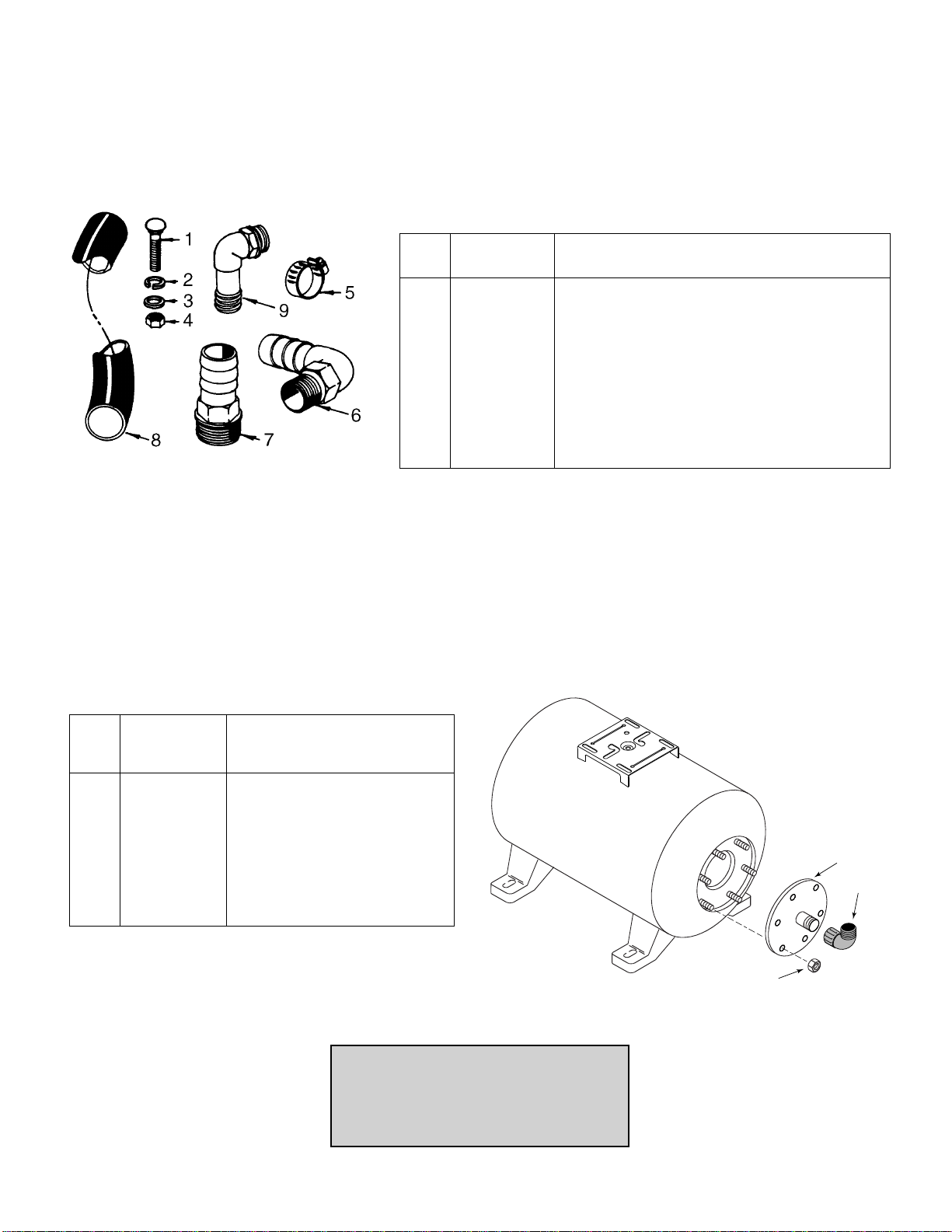
6. Lay tank on side and remove six (6) nuts from studs.
Tap cover to break seal and remove cover assembly
from tank. You can now see the vinyl bag. See Figure
11.
7. Before removing vinyl bag from groove seat in tank, BE
SURE all water is drained from bag. This can be ac-
complished by tipping tank upright and allowing re-
maining water to drain.
8. Carefully remove lip portion of bag from groove seat
and push bag into tank.
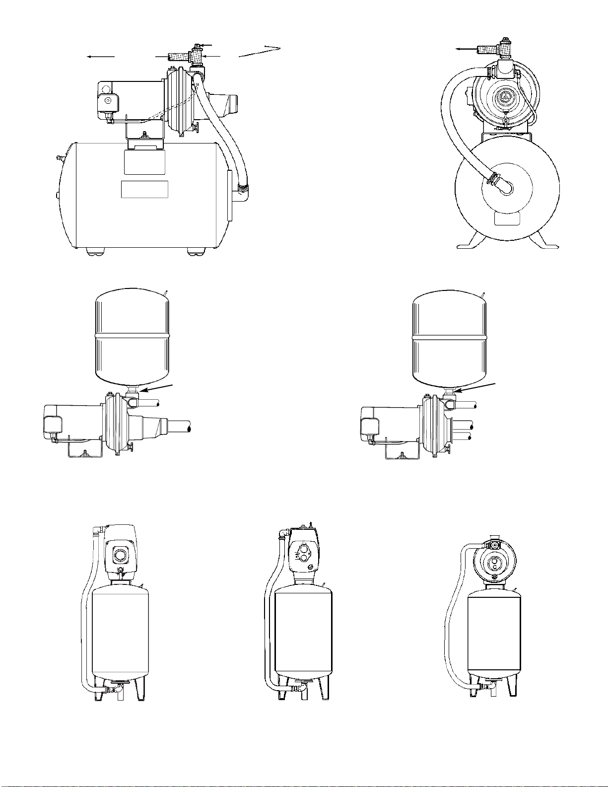
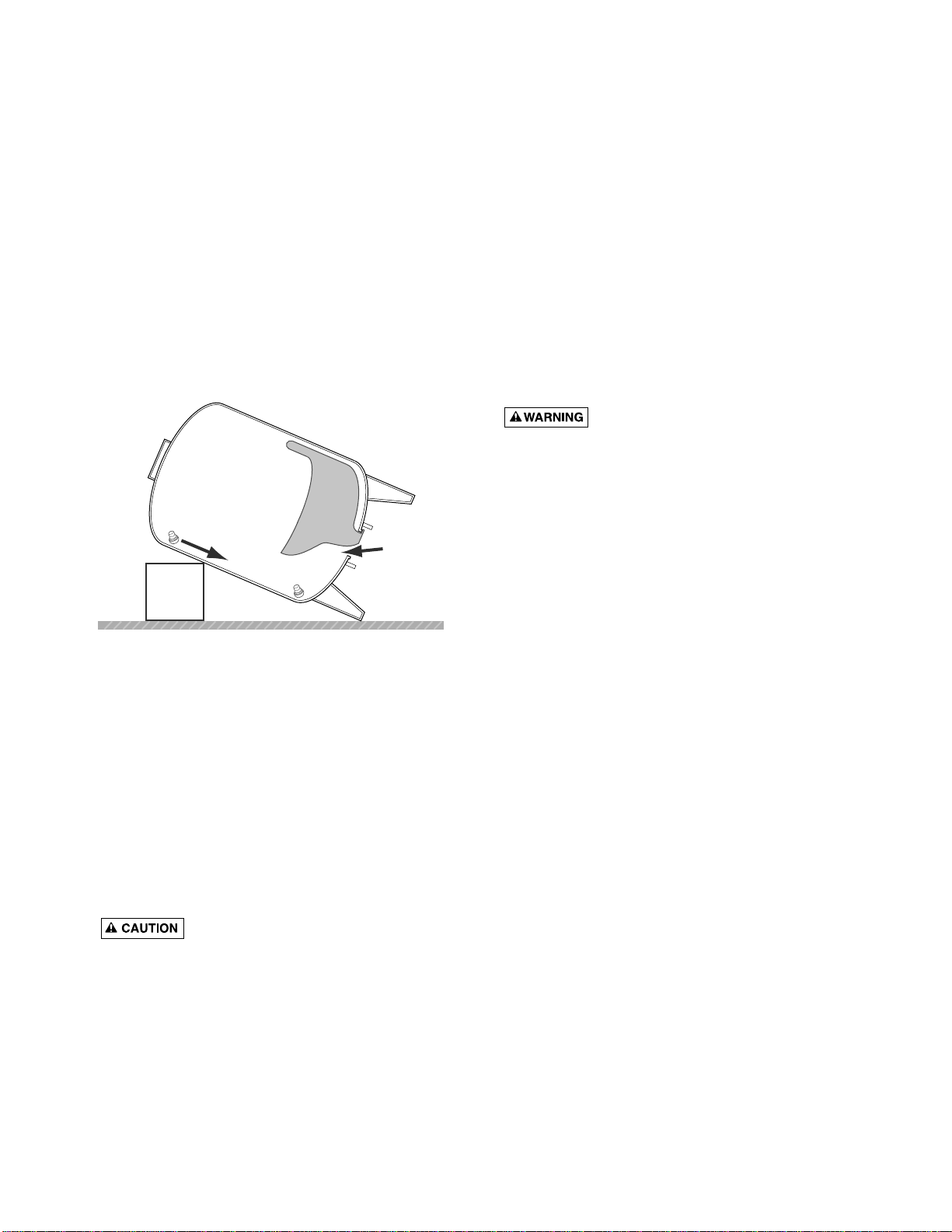
9. Block up tank as shown in Figure 13. This will allow
cutoffportionofstem toslidedowntobottomoftank.
Reach in around bag until you find it and remove it.
10. Wipe a thin film of soapy solution on top half of re-
placement stem and insert in stem hole in top of tank.
It is necessary to use a valve stem pulling tool to pull
stemthruopening.Thistollisthesame asusedbyyour
local filling station and Sears Automotive Center when
servicing tubeless tires.
11. Pullneckofbagoutoftankopeningandseatin groove.
BE SURE ring groove is clean.
12. Clean sealing surface of cover assembly and place on
studs.
13. Hand tighten all nuts on studs.
It is important that nuts be tightened as
follows: First, hand tighten all nuts. Then tighten one
nut to a snug fit. Next, tighten the one opposite to a
snug fit. Proceed, tightening the others in opposite
pairs to a snug fit. Recheck all nuts in same opposite
patterns to be sure they are evenly tightened and you
have a good seal. DO NOT overtighten, as you may
twist the studs off the tank. With a torque wrench,
tighten to 85 inch pounds.
14. Tip tank upright and assemble for operation.
15. Recharge tank with proper amount of air.
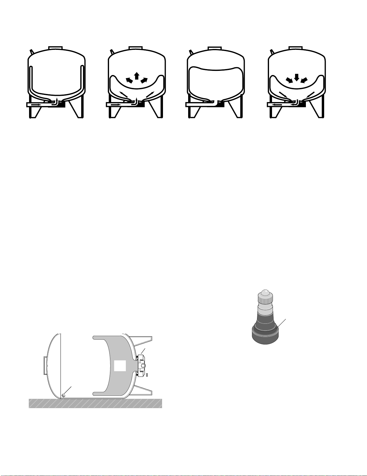
TESTING FOR LEAKAGE OF VINYL BAG
1. Disconnect power to pump.
2. Relieve (drain) ALL water in system by opening faucet
closest to tank.
3. Relieve (expel) ALL air pressure in tank by removing
core from inside of air valve.
4. Disconnect outside piping only to tank.
5. Turn tank upside down.
NOTICE: BE CAREFUL not to damage air valve when
tipping tank. Removal of air valve is not required. If
waterleaks out ofthevalvecore opening,thevinylbag
has a hole in it and must be replaced.
PROCEDURE FOR REPLACING VINYL
BAG
Be sure all air has been expelled from tank
before removing nuts.
FOR 6, 19 AND 36 GALLON TANKS
1. Carefully lay tank on its side.
2. Remove nuts around cover plate.
3. Tap covertobreakthe seal and removecoverassembly
from tank. You can now see the vinyl bag.
4. Bag cannot be removed in one piece. Wherever con-
venient, grip bag with pliers and pull outward. At the
same time cut bag with sharp knife or single-edged
razor blade. Continue pulling and cutting until bag is
completely removed.
5. Clean and dry inside of tank.
NOTICE: Before replacement bag can be inserted in tank,
it must be tightly rolled up as follows:
1. Place bag on clean surface with opening up.
2. Flatten bag and force air out.
3. Tightly roll bag towards center opening.
4. Beforecenteropening iscoveredup,forceair outofre-
maining portion of bag.
5. Finish rolling bag.
6. Asan aidforinsertingbagintank,sprinkleoutsidewith
talcum powder.
7. With tank upside down, push tightly rolled bag into
tank.
8. Put your arm in bag and push sidewalls outward. It is
NOT important that all wrinkles be removed.
9. Clean flange ring and groove of tank.
10. Pull lip of bag through tank opening and place in ring
groove.
11. MAKE SURE it seals properly in groove.
12. Clean sealing surface of cover assembly and place on
studs.
8
SERVICE HINTS
FIGURE 13
1450 0195
Cut off portion of stem
slides to the bottom of tank.
Reach in here
to retrieve stem.
13. Hand tighten all nuts on studs.
It is important that nuts be tightened as
follows: First, hand tighten all nuts. Then tighten one
nut to a snug fit. Next, tighten the one opposite to a
snug fit. Proceed, tightening the others in opposite
pairs to a snug fit. Recheck all nuts in same opposite
patterns to be sure they are evenly tightened and you
have a good seal. DO NOT overtighten, as you may
twist the studs off the tank. With a torque wrench,
tighten to 85 inch pounds.
14. Tip tank upright and reassemble for operation.
15. Recharge tank with proper amount of air.
FOR 50 AND 85 GALLON TANKS
Be sure all air has been expelled from tank
before removing nuts.
1. Carefully lay tank on its side.
2. Remove nuts around cover plate.
3. Tap covertobreakthe seal and removecoverassembly
from tank. You can now see the vinyl bag.
4. Bag cannot be removed in one piece. Wherever con-
venient, grip bag with pliers and pull outward. At the
same time cut bag with sharp knife or single-edged
razor blade. Continue pulling and cutting until bag is
completely removed.
5. Clean and dry inside of tank.
6. Place bag on its side on dry clean surface.
7. Flatten bag and force air out.
8. Starting on one side, tightly roll bag to other side.
NOTICE: Before opening is rolled closed, force re-
maining air out.
9. Finish rolling bag.
10. As a aid for inserting bag in tank, sprinkle outside with
talcum powder.
11. With tank on its side, push tightly rolled bag into tank
opening.
NOTICE: Pushbag intank only the length ofthe rolled
bag.
12. Insertarminbag andpushsidewallsoutward.Itis NOT
important that all wrinkles be removed.
13. Clean flange ring and groove to tank.
NOTICE: Two people are required for the following
steps:
14. Holding the bag, stand tank open end up.
NOTICE: DO NOT damage air valve. It may be of help
to lean tank in corner.
15. Pull lip ring of bag through tank opening and place in
ring groove.
16. MAKE SURE it seats properly in groove.
17. Clean sealing surface of cover assembly and place on
studs.
18. Hand tighten all nuts on studs.
It is important that nuts be tightened as
follows: First, hand tighten all nuts. Then tighten one
nut to a snug fit. Next, tighten the one opposite to a
snug fit. Proceed, tightening the others in opposite
pairs to a snug fit. Recheck all nuts in same opposite
patterns to be sure they are evenly tightened and you
have a good seal. DO NOT overtighten, as you may
twist the studs off the tank. With a torque wrench,
tighten to 85 inch pounds.
19. Tip tank upright and reassemble for operation.
20. Recharge tank with proper amount of air.
9
SERVICE HINTS
10
To order parts, call:
Sears Product Service
1-800-366-7278
PUMP TO TANK FITTINGS PACKAGE NO. 2788
SEARS CAPTIVE AIR®TANK
(19 GALLON) MODEL 390.291352
REPAIR PARTS
Pump to tank fittings Package No. 2788 is not furnished.
You may purchase it at your local Sears Store. Required to install all SEARS Captive Air®Tanks with shal-
low/deep well jet pump.
1
2
3
KEY PART PART
NO. NO. DESCRIPTION
1 U30-701ZP Bolt - 3/8” - 16 x 1-3/4” Lg. (2 Req.)
2 U43-12ZP Lock Washer - 3/8” (2 Req.)
3 U43-62ZP Flat Washer - 3/8” (2 Req.)
4 U36-38ZP Nut - Hex 3/8” - 16 (2 Req.)
5 U19-55SS Clamp - Hose (2 Req.)
6 U78-770P Elbow - 3/4” Pipe Thread by 1” Insert
7 U78-777P Adapter - 1” Pipe Thread by 1” Insert (2 Req.)
8 U74-37J Hose
9 U78-769P Elbow - 1” (2 Req.)
REPAIR PARTS
MODEL
KEY 390.291352 PART
NO. PART NO. DESCRIPTION
• U20-13 Bag - Vinyl
• U212-160† Air Valve w/Cap
1 U131-167 Inlet Flange Assembly
• U31-303P Tank Flange Cover
2 U78-796P Elbow 1” FPT x 1” Insert
3 U36-190ZP† Nut 5/16 - 18 Hex (6 Req.)
• F642-9301 Owner’s Manual
• Not Illustrated.
† Standard hardware item, may be purchased locally.
11
To order parts, call:
Sears Product Service
1-800-366-7278
SEARS CAPTIVE AIR®TANK
390.291552 390.291652 390.291690 390.291751
Key 19 Gallon 36 Gallon 50 Gallon 85 Gallon Part
No. Tank Tank Tank Tank Description
1 U20-8 U20-9 U20-14 U20-14 Bag Vinyl
2 U131-167 U131-167 U131-169 U131-169 Flange Cover
3 U36-190ZP† U36-190ZP† U36-190ZP† U36-190ZP† Nut - 5/16 - 18 Hex. (6 Req.)
4 U78-806P U78-806P U78-934P U78-934P Elbow
5 U212-160† U212-160† U212-160† U212-160† Air Valve w/cap
• F642-9301 F642-9301 F642-9301 F642-9301 Owner’s Manual
•Not Illustrated. †Standard hardware item, may be purchased locally.
5
1
2
3
4
272 0893
MODEL 390.291552 (19 GALLON)
MODEL 390.291652 (36 GALLON)
MODEL 390.291690 (50 GALLON)
MODEL 390.291751 (85 GALLON)
NOTICE: 50 and 85 gallon tanks
are not equipped with mounting
bracket.Installpumpbesidetank
as shown.
For the repair or replacement parts you need
Call 7 am - 7 pm, 7 days a week
1-800-366-PART
(1-800-366-7278)
For in-home major brand repair service
Call 24 hours a day, 7 days a week
1-800-4-REPAIR
(1-800-473-7247)
For the location of a
Sears Repair Service Center in your area
Call 24 hours a day, 7 days a week
1-800-488-1222
For information on purchasing a Sears
Maintenance Agreement or to inquire
about an existing Agreement
call 9 am - 5 pm, Monday-Saturday
1-800-827-6655
MAINTENANCE
AGREEMENT
America's Repair Specialists
REPAIR SERVICES
America's Repair Specialists
REPAIR SERVICES
America's Repair Specialists
REPAIR SERVICES
OWNER’S
MANUAL
Model No.
390.291352
390.291552
390.291652
390.291690
390.291751
The model number of
your Captive Air®Tank
will be found on a label
attached to the tank.
When requesting service
or ordering parts, always
give the following
information:
• Product Type
• Model Number
• Part Number
• Part Description
Sears, Roebuck and Co., Hoffman Estates, IL 60179 U.S.A.
CAPTIVE AIR®TANK

This manual suits for next models

4

Other Sears Tank Equipment manuals

Sears CRAFTSMAN 390.291198 User manual

Sears

Sears CRAFTSMAN 390.291198 User manual

Sears Kenmore 390.291195 User manual

Sears

Sears Kenmore 390.291195 User manual

Popular Tank Equipment manuals by other brands

Kemper FK-5 installation instructions

Kemper

Kemper FK-5 installation instructions

DeVilbiss QM T-5 Series Service bulletin

DeVilbiss

DeVilbiss QM T-5 Series Service bulletin

TransTank AquaTrans Operator's handbook

TransTank

TransTank AquaTrans Operator's handbook

PA MI63-50 Instruction book

PA

PA MI63-50 Instruction book

WELBA WTS-200 Installation and operating instructions

WELBA

WELBA WTS-200 Installation and operating instructions

Vixen Air VXT7300SS installation guide

Vixen Air

Vixen Air VXT7300SS installation guide

SATA FDG 24 operating instructions

SATA

SATA FDG 24 operating instructions

Pepperl+Fuchs LVL-Z124 manual

Pepperl+Fuchs

Pepperl+Fuchs LVL-Z124 manual

Varec 6700 Installation and operation instructions

Varec

Varec 6700 Installation and operation instructions

Jaspi AKVATERM AKVA PRO 1000 EK Operation and installation

Jaspi

Jaspi AKVATERM AKVA PRO 1000 EK Operation and installation

Gardena 4000/5 eco operating instructions

Gardena

Gardena 4000/5 eco operating instructions

manuals.online logo
manuals.online logoBrands
  • About & Mission
  • Contact us
  • Privacy Policy
  • Terms and Conditions

Copyright 2025 Manuals.Online. All Rights Reserved.