SeeMeCNC DropLit User manual

DropLit Assembly Guide
Welcome to the Assembly Guide for the DropLit 3D printer.
Version 0.50, September 2 th, 2014
Copyright 2014 by Gene Buckle
Licensed as Creative Commons Attribution-ShareAlike 3.0
Questions or corrections should be emailed to geneb@deltasoft.com
Disclaimer text provided by LulzBot
1

DropLit Assembly Guide
READ ME FIRST!
READ THIS MANUAL COMPLETELY BEFORE ASSEMBLING AND POWERING UP
YOUR PRINTER!
Hazards and Warnings
The SeeMeCNC DropLit 3D printer has motorized parts. When the printer is in operation always be
aware of possible hazards.
lectric Shock Hazard
Never open the electronics bay of the printer while the printer is powered on. Before removing
the access door, always power down the printer and unplug the AC line cord.
Fire Hazard
Never place flammable materials or liquids on or near the printer when powered on or in
operation.
Pinch Hazard
When the printer is in operation, take care to never put your fingers in the moving parts,
including the belts, pulleys or gears. Also, tie back long hair or clothing that can get caught in
the moving parts of the printer.
Static Charge
Make sure to ground yourself before touching the printer, especially the electronics.
lectrostatic charges can damage electronic components. To ground yourself, touch a
grounded source.
Age Warning
For users under the age of 18, adult supervision is recommended. Beware of choking hazards
around small children.
2

DropLit Assembly Guide
Table of Contents
READ ME FIRST!.....................................................................................................................................2
0 – Introduction and Acknowledgments....................................................................................................4
1 – Required and Optional Tools And Materials........................................................................................5
2 – Visual Bill of Materials........................................................................................................................6
3 – Getting Started: Building the Front Cover.........................................................................................16
4 – Building the DropLit Chassis.............................................................................................................23
Mounting the Arduino Uno.............................................................................................................23
Assembling the Chassis..................................................................................................................25
Installing the T-Slot Extrusion........................................................................................................34
5 – Assembling the Drive System & Carriage.........................................................................................38
Installing the Stepper Motor...........................................................................................................38
Installing the Carriage.....................................................................................................................43
Installing the Z Axis Drive Rod......................................................................................................50
6 – Things Electronic!..............................................................................................................................53
Installing the Limit Switch.............................................................................................................53
Installing the Power Supply & Power Switch................................................................................56
Wiring & Installing the gShield......................................................................................................60
7 – Final Assembly...................................................................................................................................64
Assembly & Installation of the Mirror Support..............................................................................64
Final Assembly...............................................................................................................................67
3

DropLit Assembly Guide
0 – Introduction and Acknowledg ents
I’d like to welcome you to the DropLit assembly guide!
Please read this entire guide before you begin assembly of your new DropLit! It will help you
avoid any unpleasant surprises and will ensure that you’ve got everything you need BEFORE you need
it! Understand that the photographs in this assembly guide do NOT tell the whole story of each step!
Make sure you read and understand the accompanying text for each step!
A quick note on the Arduino Uno and the gShield. These two devices work in combination to
control the DropLit and are very static sensitive, so please don't take them out of the bags they ship in
until you're ready to install them.
Many thanks to Michael Hackney – he trailblazed the first beta DropLit build and my job would
have been a LOT more difficult without his stellar efforts.
4

DropLit Assembly Guide
1 – Required and Optional Tools And Materials
Before you begin assembly of your DropLit, please make sure you’ve got everything on the
following list of tools and additional materials.
•P1 & P2 sized Phillips screwdrivers
•Small flat tip jeweler's screwdriver
•Standard flat head screwdriver
•5/32” Allen Wrench
•5/16” Wrench
•3/8” Wrench
•Wire strippers
•Wire cutters
•Battery powered screwdriver. If you ever needed an excuse to buy one of these, THIS IS IT.
•Soldering Iron
•Thin Super Glue.
•Waxed lacing cord. This is optional, but you can use this in place of wire ties in pretty much
any application. You can find it here: http://www.skygeek.com/wht-string.html. While
expensive, you'll never really need to buy a wire tie again and it'll likely last you the rest of your
life. :)
•Q-Tips
5

DropLit Assembly Guide
2 – Visual Bill of Materials
Your DropLit kit should contain a wrapped pack of Melamine parts, three bags of parts (two
bags of hardware, one bag of electronic parts) a short section of aluminum extrusion and a power
supply.
The Melamine parts are covered with a special cutting mask that prevents the laser cutting
operation from depositing laser cutting byproducts on the Melamine surface. You'll need to remove all
of this material before beginning construction.
This process is called the Five Stages of Masking Tape.
1. Denial - Oh there's no way I need to scrape all this tape off those parts? Do I?
2. Anger - @#$%@#! This sucks! I've NEVER SEEN SO MUCH TAPE IN
ONE PLACE IN MY LIFE!
3. Bargaining - “Well hi there, Significant Other! Would you PLEASE remove
all this tape for me? PLEASE?”
4. Depression - This tape hates me. *sobs quietly*
5. Acceptance - Well I suppose if I'm ever going to get this thing built, I'd better
get on with it and get all this tape removed...*sigh*
Ok, it's not THAT bad, it just seems like it. It beats having sticky residue all over your nice and
clean Melamine parts. :)
6
Fig. 2-1: DropLit package contents.
DropLit Assembly Guide
For those that aren't sure how to identify the various screw types, Bolt Depot has made available
some excellent references. I would recommend Fastener Basics (http://www.boltdepot.com/fastener-
information/Printable-Tools/Fastener-Basics.pdf) and their Fastener Type Chart
(http://www.boltdepot.com/fastener-information/Type-Chart.aspx).
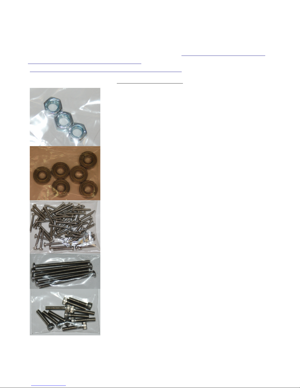
DropLit Hardware Bag #1
(___) (3) M5 Zinc Plated Nut
(___) (6) 1/4” ID x 5/8” OD x .1 6” Ball Bearing (R4ZZ)
(___) (57) #6-32 x 1” Phillips Pan Head Screw 18-8 SS
(___) (6) #6-32 x 2” Phillips Pan Head Screw 18-8 SS
(___) (10) #6-32 x 5/8” Socket Head Cap Screw 18-8 SS
7

DropLit Assembly Guide
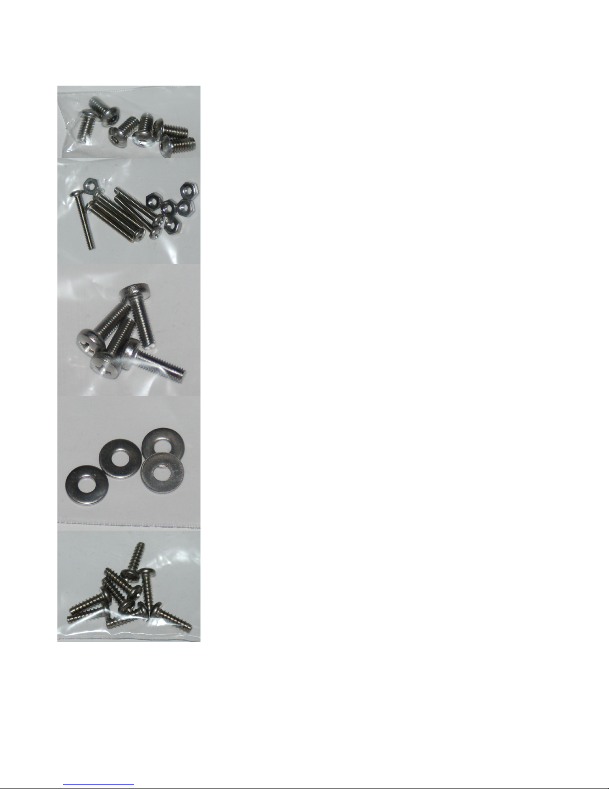
(___) (75) #6-32 Nylon Lock Nut SS
Rubber foot pack containing
(___) (4) Leg for 44010 Foot
(___) (4) Rubber Foot (44010)
(___) (4) #10-32 x 5/8” Pan Head Screw (Nylon)
(___) (4) #10-32 Nylon Finish Nut
(___) (4) Plastic Bearing Roller 1/8” ID x 3/8” OD x 0.156” W
(___) (4) #6-32 x 1/2” Slotted Pan Head Screw (Nylon)
(___) (6) 1/4-20 T-Slot Nut
8
DropLit Assembly Guide
(___) (6) 1/4-20 x 1/2” Button Head Cap Screw (SS)
(___) (6) #2-56 x 5/8” Pan Head Screw
(___) (6) #2-56 Finish Nut
(___) (4) M3-.05 x 10mm Phillips Pan Head Screw (SS)
(___) (4) #4 SAE Flat Washer (SS)
(___) (8) #6 x 1/2” Phillips Pan Head Sheet Metal Screw (SS)
DropLit Assembly Guide
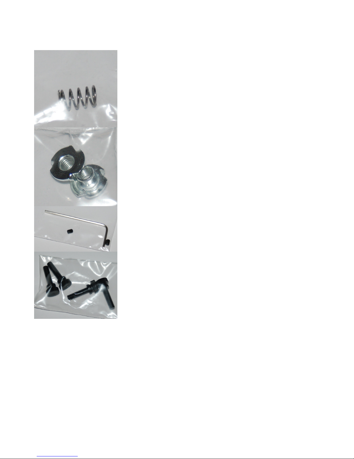
(___) (1) .300” OD x .030 wire x 1/2” SS Compression Spring
(___) (2) #10-32 T-Nut
(___) (2) M3-.5 x 6mm Allen Set Screw
(___) (1) 1.5mm Allen Wrench
(___) (4) #10-32 x 3/4” Knurled Thumb Screw (Black Nylon)
10
Table of contents
Other SeeMeCNC 3D Printer manuals

SeeMeCNC
SeeMeCNC Rostock Max v3 User manual

SeeMeCNC
SeeMeCNC Rostock MAX v2 User manual

SeeMeCNC
SeeMeCNC Rostock MAX v2 User manual

SeeMeCNC
SeeMeCNC orion delta User manual

SeeMeCNC
SeeMeCNC orion delta User manual

SeeMeCNC
SeeMeCNC orion delta User manual

SeeMeCNC
SeeMeCNC Rostock Max v3 User manual

SeeMeCNC
SeeMeCNC rostock max v2.0 User manual

SeeMeCNC
SeeMeCNC Artemis 300 User manual

SeeMeCNC
SeeMeCNC Rostock Max User manual


