SeeMeCNC Delta User manual

SeeMeCNC Delta 3D Printer Manual
First Edition
v1.00 – January 13th, 201
Cura v3.1.0
Copyright 201 By Gene Buckle – [email protected]
Licensed as Creative Commons, Attribution-ShareAlike 3.0
Official support is available through supp[email protected]
As a SeeMeCNC printer owner, you’ll also find a ton of great resources on the
forums at forum . seemecnc . com
1

0 – Introduction – Read Me First!
This document is your instruction manual for your new SeeMeCNC® 3D printer machine.
Before using your new 3D printer thoroughly read and understand this manual for safe and
effective operation of the machine.
2
Warning
Adult supervision required. Children under 18 years of age require supervision.
Risk of Fire. Do not leave machine unattended.
Use genuine parts manufactured or designated y SeeMeCNC.
Keep a copy of this manual near the machine, easily accessi le to all operators.
Use of this machine is at your own risk.
Personal property damage, serious injury or death can result from not following
instructions or warning in the manual or misuse of the machine.
Automatic machine can start unexpectedly. Pay close attention and keep clear
while power is connected to the machine
The machine power supply is connected to AC voltage
and can e hazardous. Disconnect power efore
servicing this machine.
The hot end of the machine can reach very high
temperatures of 700F and can cause serious urns.
The heated print surfaces (heated ed) can also reach
temperatures high enough to cause severe urns. Allow
oth to cool for 20 minutes after turning off power.
Use caution near moving parts of the machine. Keep
ody and loose articles clear.
Poisonous gas, smoke, or fumes could e emitted y some materials you could
use with the machine. In such case, you should install ventilation.
Choking Hazard. This machine contains small parts and
can produce small parts which can e a choking hazard
to children.
Visit http://www.seemecnc.com to contact us if you have any questions.

IMPORTANT
This manual was written with the assumption that you’ve already gone through the Cura
Quick Setup Guide. That guide will show you how to add your printer to Cura and how to import
the pre-built slicing profiles that SeeMeCNC has developed. If you haven’t yet had the
opportunity to go through that guide please do so now.
Tasks involving controlling your printer will be discussed from the point of view of the
Duet 3D printer controller interface. If your printer has a different controller the steps shown in
this guide won’t apply.
3

Table of Contents
0 – Introduction – Read Me First!.................................................................................................2
1 – The Cura Interface.................................................................................................................5
2 – Printing with Cura.................................................................................................................13
3 – Introduction to the Custom Options......................................................................................18
4 – The Cura Material and Profile Managers..............................................................................24
5 – Print Setup – Advanced Options..........................................................................................28
6 – A Strategy for Successful (and Great!) Prints.......................................................................34
4

1 – The Cura Interface
The Cura interface is very straightforward and easy to understand. Let’s take a few
minutes to get familiar with it!
1. Open File. This is the button you’ll click when you want to load an object into Cura.
2. Adjustment Controls. These buttons control the size orientation and position of the model
on the build plate. We’ll cover them in detail later.
3. These are the view orientation controls. They allow you to change the viewing position of the
model on the build plate with the click of a button. To the right of the orientation controls is a
drop-down that will allow you to select the type of view that the model will be presented in. The
choices are “Solid view” “X-Ray view” and “Layer view”. Like the adjustment controls we’ll
cover these views in detail later.
4. This gray area is the non-printable area of the bed.
5. The printable area of the bed.
6. Information on the currently loaded model. It includes the filename of the model as well as
the amount of space it occupies on the printed bed.
7. Print job information. It includes estimates on the amount of time the job will take to print and
how much the printed part will weigh. If there’s enough information in the material description it
may also include the cost of the material needed to print the part.
5

. Save to File – this allows you to save the generated gcode to your local computer or an SD
card if you’ve got one inserted.
9. Printer and material settings panel.
Now that you’ve got an idea of what’s going on with the Cura interface let’s download a
model so we can explore Cura more fully.
Open a browser and go to https://repables.com/r/118/. This is a tiny medallion with the
SeeMeCNC “blinky” eyes logo on it.
Once you’ve got the file downloaded and un-zipped click on the Open icon
to load the model into Cura. You’ll notice that it doesn’t appear that Cura loaded
anything at all but it really did! Click on the “top down view” icon highlighted below.
You’ll notice that there’s a tiny yellow dot in the center of the build plate.
That’s actually the medallion! Because of how Cura interprets the size of the
model this makes for an excellent demonstration model. We’re going to need to resize the
model in order to make it large enough to make a good first print example.
Adjustment Tools
In order to make the model easy to click on we’ll have to zoom in a bit on the build plate.
You can zoom in either by using the scroll wheel on your mouse or you can hold down the
space bar while you move your mouse vertically. Once you can easily see the medallion model
click on it. If the Scale tool doesn’t open automatically click on it.
As you can see Cura thinks the medallion model as being a minuscule 2.8mm wide and
only 0.5mm tall! Since we’re not printing ant medallions we’ve got to scale this thing up!
Click in the box next to the red “X” and type in “25.4”. This will scale the whole model up
so that it’s around 1 inch in diameter and can be more easily printed. If you want to make it
bigger than that go for it! Make sure you’ve got Uniform Scaling checked. This ensures that
the other parameters are scaled to the same percentage as the axis you’re changing – thus
“uniform” scaling.
6
Scaling tool selected.

Here’s what the scaled up medallion looks like in Cura:
There’s three other adjustment tools in Cura that will allow you to move a model around
the build plate rotate the model or mirror the model.
Moving the model is easy just click on the model to select it and then click & drag to
move it where you like. You can also click on the red green or blue axis arrows to move the
model only in one axis.
7
Medallion scaled up!
Move Model

The rotation tool will allow you to change the orientation of the model on the build plate.
This comes in very handy if the model you load isn’t oriented in a “printable” position.
When you select the rotation tool and then your model you’ll see three “axis rings”
appear around your part. These rings can be “grabbed” (click & hold) by your mouse cursor in
order to rotate the model how you need it. As you rotate the model you’ll notice a little tool-tip
that appears and will show the angle in degrees that your rotation is currently at.
If you’ve got Snap Rotation checked the
rotation will “snap” every 5 degrees. If you
uncheck it movement is at 1 degree increments.
The rotation tool includes two special
buttons. Reset and Lay Flat. The Reset button
will return your model’s orientation to whatever it
was
8
Rotation tool
Axis of rotation rings.
Showing 15 degrees of rotation in the X
axis.
Reset & La Flat.

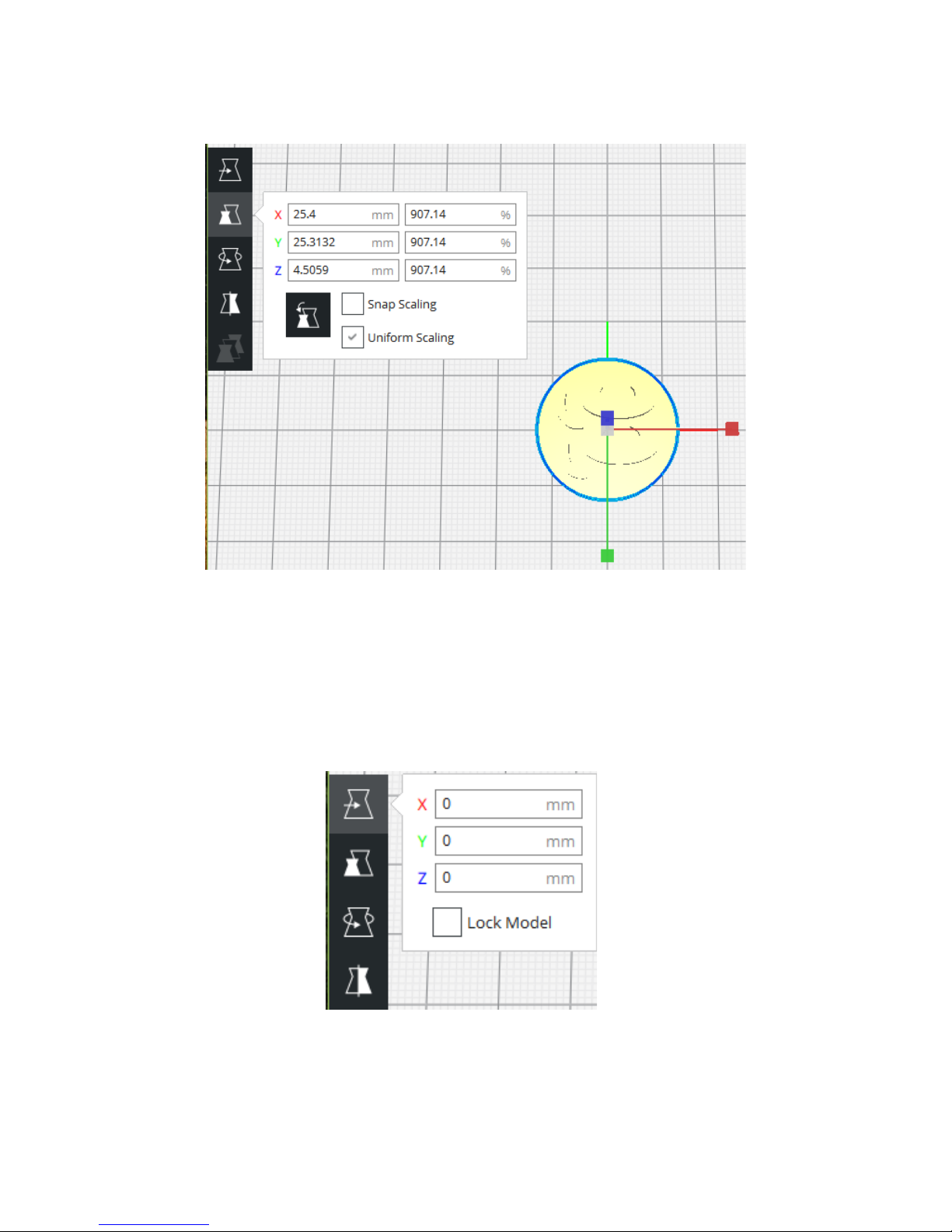
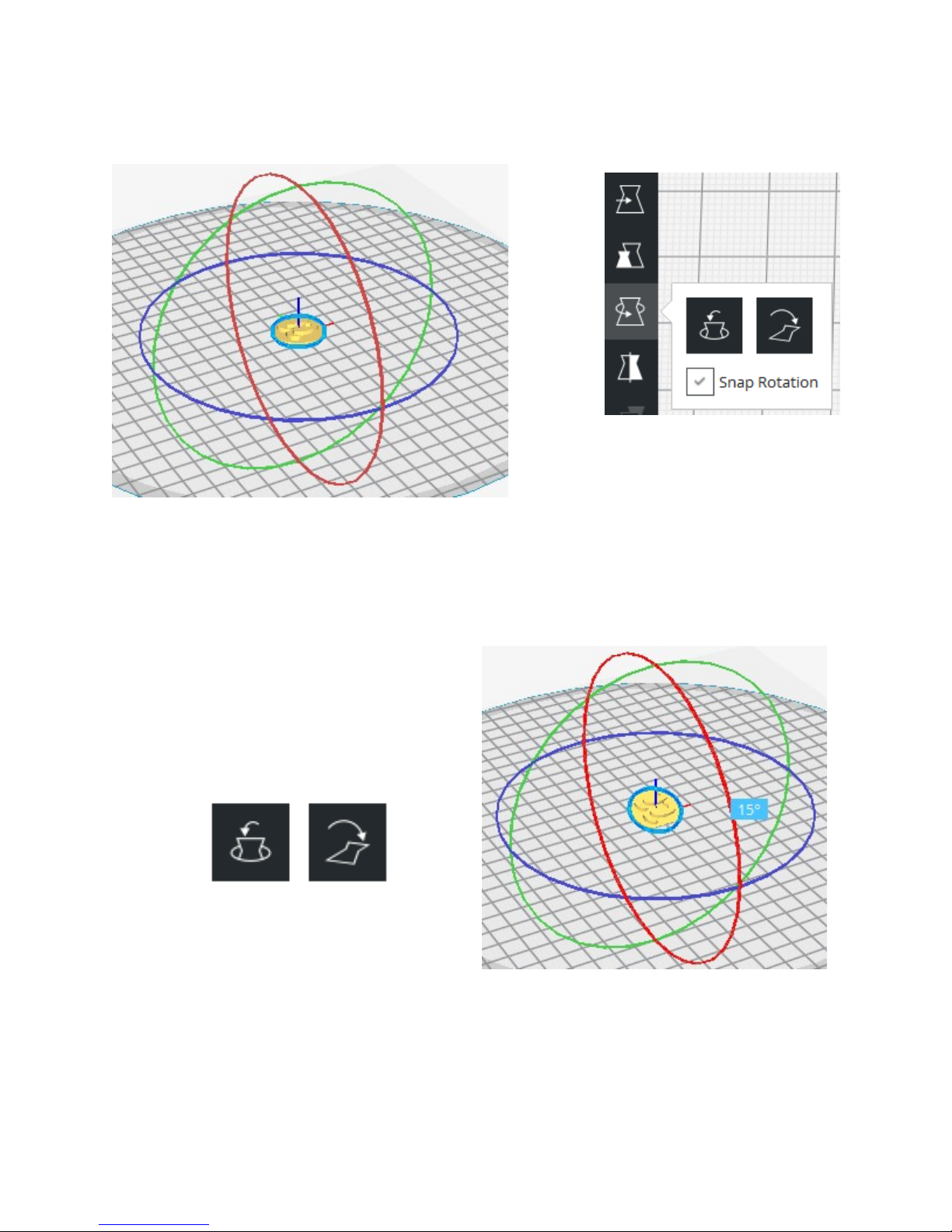
The last adjustment tool we’ll take a look at is Mirror. When you select your model and
click the Mirror tool mirror axis control points will appear around the selected model similar to
those shown on the right.
These control points allow you mirror your model
along the X (red) Y (green) or Z (blue) axes.
View Orientation & Type Controls
In the upper right area of the model view window you’ll see five block shaped icons like
those below.
These icons are basically “view presets” and will adjust the view of the
model based on which is clicked. From left to right they are: Isometric
Front Top Left and Right. Click on each one to see how they affect
the display of your currently loaded model.
In addition to the view presets you can use your mouse to move your viewpoint. Hold
down your right mouse button and move the mouse around. You’ll notice that the “horizontal”
motion of the mouse controls the rotation of the view and the “vertical” motion of the mouse
controls the tilt of the view. Your mouse wheel controls the zoom. If you hold down your shift
key then right click & move you’ll see that you can move the build volume around without tilting
or rotating it. This will allow you to visually center your model in the screen when you zoom in.
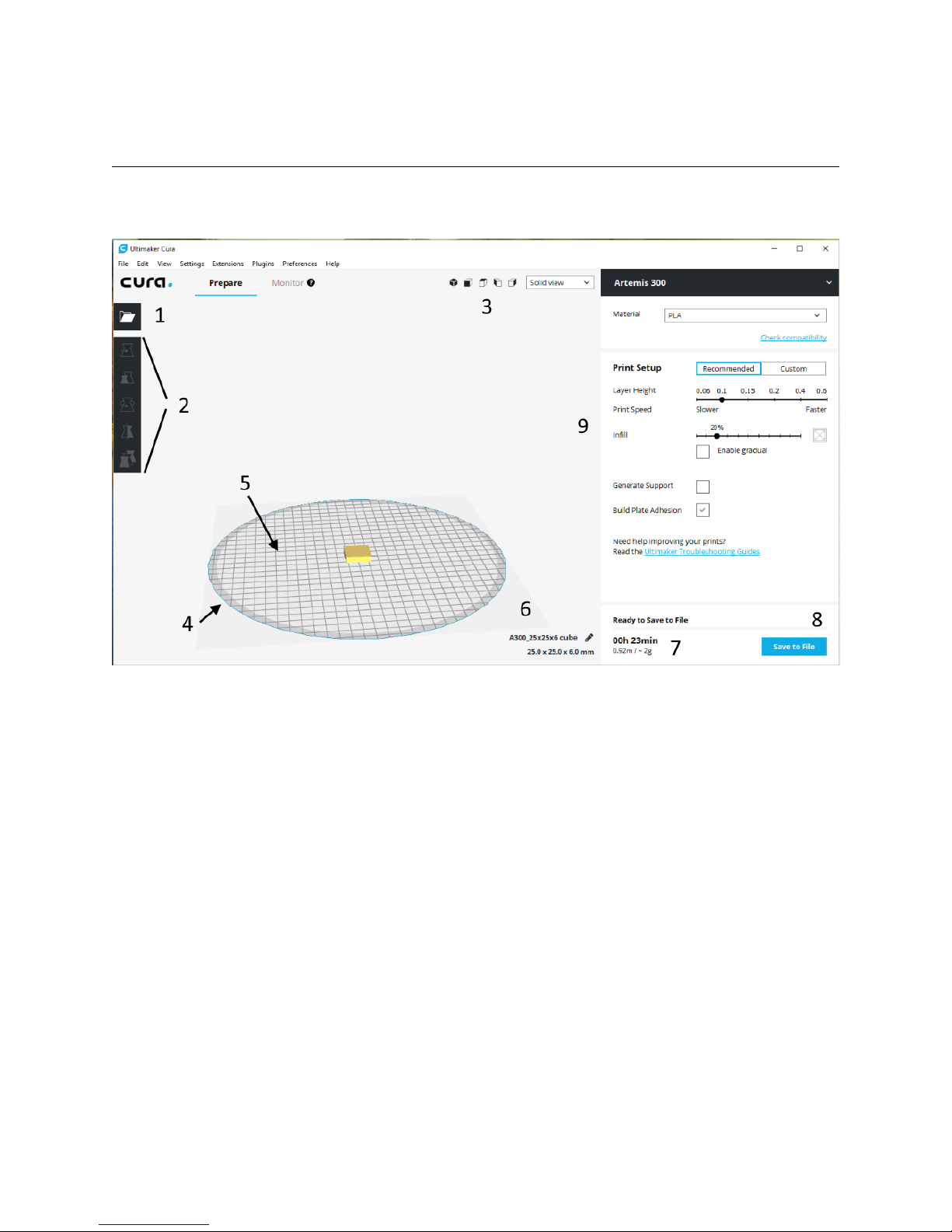
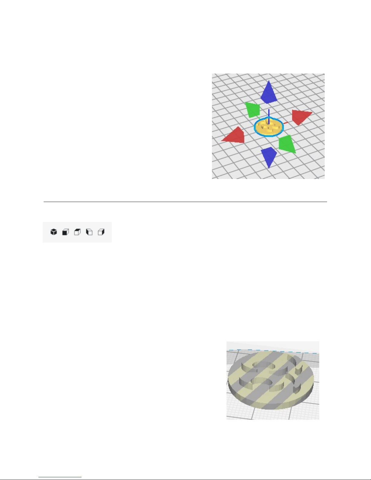
The View Type control allows you to specify how you want to see your model drawn in
the work space. Your choices are Solid view X-Ray view and Layer view. The default is
Solid view. Solid view will show a shaded representation of
the currently loaded or selected model. If your model is
positioned outside the printable area for your printer the
model will be drawn with stripes going through it as shown in
the lower right.
The X-Ray view can be used to check to see if there’s
any errors in the internal geometry of the model. Any errors
that Cura detects will be shown in red.
9
Mirror control points.
Invalid model location.

The Layer view gives you the ability to examine each layer of your model as it would be
printed. This allows you the opportunity to see how changes you make to the print settings
panel will effect how the model prints. Below is an example of the layer view showing layers 1
through 32.
The example above is typical of the standard Cura Layer view. It includes a color key
that shows you each element that makes up a layer. The slider on the right is set up to show
you layers 1 through 32. If you only wanted to view a single layer you could click and drag the
black marker up so that it’s right below the blue layer marker. Note that clicking on a marker will
make it “active’ and change its color to blue.
10
La er displa
Showing a single la er.

The Printer and Material Settings Panel
The Printer and Material Settings Panel is where you’ll choose what printer you’re going
to print with what material you’re going too use and what settings will be used for that print.
As you can see on the right I’ve got
an Artemis 300 printer selected. This
model was added when following the Cura
quick setup guide. The material settings
included in Cura offer a great baseline for
generic materials as well as a number of
vendor specific materials. Note that the
material settings only provide a starting
point for a number of settings and those
settings can (and usually are) over-ridden
when you select a printing profile.
The “Recommended” setting cuts
down the myriad of print configuration
selections to just the few you see on the
right. If you want to adjust other settings or
choose one of the SeeMeCNC profiles you
imported you’ll need to click on the
“Custom” button.
The Layer Height slider controls
how thick each print layer will be
expressed in mm. Since the layer height
directly effects print speed the Cura
authors have grouped Print Speed with
the Layer Height slider. Conversely print
speed effects layer height.
The Infill slider is going to dictate how “solid” your part is. The density of the infill is
approximately shown by the indicator at the right end of the slider. As you change the infill
percentage you’ll see that indicator change. Keep in mind that it’s not a precise indicator of the
infill – it just gives you a “categorical” idea of the infill. (empty light heavy or full)
Enable Gradual will gradually increase the infill percentage as the print nears the top of
the model you’re printing. This can help with supporting the top layers of a print.
Generate Support can be checked if you are printing a model with severe overhangs.
This is a setting I’ll cover in more detail when we go over the various settings available when
Custom is active.
11
Print and Material Settings

Build Plate Adhesion will tell Cura to print a brim or a raft to help the part stick to the
print bed. A brim is basically an extended first layer. It will print a series of concentric
perimeters around your model starting at the edge of the model and working out. This provides
more surface area for the model to adhere to the bed with. A raft is a thin platform that’s printed
before your model begins to print. You’ll end up with your model sitting atop an easily
removable raft of plastic. Rafts can be very helpful with materials like ABS that can be tricky to
get to stick to the bed.
These (and other) settings work together to “slice” your model up into a series of layers
that are as thick as your selected layer height. The result of this is a set of instructions that your
printer will follow for each printed layer in the model. After the slicing process is complete Cura
is ready to save out a “gcode” file which is a list of instructions your printer will read in order to
print your part.
Going into the details of G-code is beyond the scope of this guide but if you'd like to
learn more you can check out the following resources: http://en.wikipidia.org/wiki/G-code and
http://reprap.org/wiki/G-code.
Now that you’ve got an understanding of how the main interface works let’s move on
to…
12

2 – Printing with Cura
For this section make sure you’ve got the SeeMeCNC medallion model loaded and
scaled up so that the X axis is 25mm or more
One thing you’ll want to have handy is 91% Isopropyl Alcohol wipes – these are really
handy to get fingerprints off your bed glass with. No so much after you’ve put glue down but
certainly before hand.
If you're printing on a regular glass surface it's
recommended that you apply a thin layer of Elmer's
Disappearing Purple glue to the glass. You'll want to apply two
perpendicular layers of glue on to the heated bed. Follow the
simple pattern shown on the right. The green lines represent
the first layer and the red lines represent the second. The idea
is to lay down a thin even layer with no spaces between each
“lane” of glue. Let the base layer completely dry before applying
the second layer. Let THAT layer dry before starting a print.
If you’re used to using other slicers you’ll notice that
there’s no “slice” button. With Cura if there’s a model loaded it’s almost always already sliced.
Each time you load or adjust a model (position scale etc.) or change a printing parameter Cura
will automatically re-slice the model. This ensures that as soon as you’re ready to print you
don’t need to manually start a slicing process.
So let’s go ahead and print the SeeMeCNC Blinky Eye medallion using one of the
SeeMeCNC pre-defined configurations. In order to select a new profile you’ll click on the
Custom button and then chose the profile you want from the Profile drop-down. In my case I’ll
chose the SE300 PLA Default profile because I’m using an Artemis 300 equipped with an
SE300 hot end. You’ll want to choose the profile that most closely matches the hot end you’ve
got installed on your printer.
13
Glue application example.
New profile selected.

Once you’ve chosen the new profile Cura will slice your model based on these new
settings. When it’s done you’ll see “Ready to Save to File” appear right above the estimated
print time. Your print time may not match the example below that’s okay!
Click on the Save to File button in order to save the gcode that Cura generated when it
sliced the model. You’ll then have a file you can upload to your printer!
Open a web browser and open up the printer control page for your printer. Click the G-
Code Files link and then click the Upload G-Code File(s)” button in order to upload the file you
just saved to your printer. The button is going to be in the right side of your browser.
When your file is uploaded you’ll be presented with a dialog that looks similar to the one
shown below. Click on the Close button to continue.
14
Read to save!
G-Code Files link..
Upload File button.

To print your newly uploaded file just locate the filename in the list and click on it.
When you click on the link you’ll be presented with a confirmation dialog as shown
below. Click on the Yes button to start the print!
With the start of the print job the printer is going to heat up the heated bed first and then
the hot end. As you can see below it’s currently heating the bed.
The Active column shows
the target temperature while the
Current column shows the actual
temperature as measured by the
controller. When the target
temperature is reached by the bed
the printer will begin to heat the hot
end. Once that temperature is
reached the print job will begin!
The following pages show the results of this print job. I’ve increased the size of the part
to 50mm in order to make it more easily seen.
15
Filename link
Start Print confirmation dialog.
Bed heat active.

As you watch the print start you’re going to see something similar to the image below.
#1 above is the “skirt” that the default profile uses to prime the hot end with plastic. If
you’d configured Cura to print a brim this skirt would touch the outer perimeter of the part and
expand outward concentrically for the distance specified by the brim settings.
#2 above are the perimeters that were printed for the actual part. The photo has caught
the process just as the first infill layer has begun to print. Below you can see what this first layer
looks like.
16
Skirt & Perimeter
First la er!

When the bottom layers are done printing the infill layer will begin. In this case
occupying 15% of the interior area inside the model.
When the print finishes you should have a SeeMeCNC Blinky Eye medallion that looks
similar to the one shown below.
17
Finished!

3 – Introduction to the Custom Options
Cura is an easily accessible yet very complex slicing program. It’s got a wide range of
options that can give you complete control over nearly every aspect of the slicing process.
Fortunately for us the Cura developers have created a “default” set of custom options that
allows new users some control without burying them in dozens of options they may not need to
change. These default options can be reached by clicking the Custom print setup button.
Cura divides the options into the following 9 categories:
•Quality
•Shell
•Infill
•Material
•Speed
•Cooling
•Support
•Build Plate Adhesion
•Special Modes
Cura will present the most commonly needed options within each category at first – what
you see is not all that’s there! Let’s cover the basics of each one and then we can take some
time to investigate the more advanced parameters later. You’ll notice that some of the
categories have this symbol next to their control points: This icon indicates that there may
be hidden parameters that use values that differ from the Cura defaults. This is normal and is
the result of the SeeMeCNC supplied profiles. The profiles that SeeMeCNC supplies change
those default values in order to provide better results on their printers.
When you hover your mouse over a category heading you’ll notice that a “gear” icon
appears. This icon will open up the visibility settings for the selected category. You won’t need
that right now but later on we’ll use it to expand the available parameters you can use in Cura.
Quality covers Layer Height and Line Width. As you may have surmised Layer
Height dictates the layer thickness of each layer in the print. The thicker the layer height the
faster your print job will complete but the results can be a “rough draft” - or of a poorer surface
18
Print Options in Cura

finish than you get at thinner layers. Line Width dictates how wide the line of plastic being
extruded should be. In our case it 0.5mm which matches the diameter of the nozzle. If you
have a larger or smaller nozzle you should set Line Width to the diameter of that nozzle.
Shell contains parameters related to the exterior shell of a printed part. Wall Thickness
dictates how thick the vertical walls in the part should be. Here it’s listed in millimeters but you
can also specify it in “loops” or the number of times the hot end passes around to create the
wall. In this case it’s set to 0.8mm. Since the nozzle diameter (Line Width) is 0.5mm that
works out to 3 loops(ish). Top/Bottom Thickness dictates how thick the horizontal surfaces of
your model should be. Here it’s also 0.8mm but since the layer thickness is 0.2mm it’ll need 5
layers to create that thickness. This brings up an important point – you need to make sure that
your top layer thickness is adequate for the layer height you’re working with. Take for example
the item shown below.
This example was printed with a 0.1mm layer height
but only 3 top layers (0.3mm). Because the layer height is
so thin it takes more solid layers in order to properly fill the
spaces between the infill structure. This same part printed
with a 0.2mm layer height (0.6mm top thickness) results in
all areas being properly filled in. However the infill pattern
can be seen as a slight shadow in the top layer as shown on
the right. Adding two or more additional top layers would
have eliminated the issues presented. Bottom layers that
are fully supported by the build plat won’t exhibit similar
issues at thinner layer heights.
19
Infill bleed-through.

Infill contains parameters that control the non-visible interior structure of a printed part
as well as how strong it is – more infill makes for a stronger part. Infill Density is a percentage
that dictates how much infill will be used. Typically you’ll see anywhere from 15% to 25% used
but some parts need more some need less! It all spends on what the model is for. If you’re
printing little “toy” things like the SeeMeCNC Blinky 15% is just fine – but if you’re printing
something like a bracket or other part that’s got to be mechanically strong 80% or 100% infill
isn’t unheard of. Gradual Infill Steps can be used to reduce the infill density of a part the
further away the infill is from the outside surface of the model. This can be used to decrease
printing time as well as increase the infill density without as much of an increase in the plastic
used to print the part.
The Material category contains parameters that are mostly specific to the material that
you’re using to print with. Both Printing Temperature and Build Plate Temperature are pretty
self-explanatory. When in doubt with either parameter follow your filament vendor’s guidelines
on printing & bed adhesion temperatures. Diameter is used to tell Cura’s slicing engine how
thick the filament is. Getting this value as close to reality as possible is importance since it
dictates how material flow is going to be calculated. In order to get a good value for filament
diameter I recommend spooling off a meter or so of filament and then sample the diameter
using a pair of digital calipers. Put the average of those values into Diameter.
Flow is used to manage the flow rate of the extrusion. This is used to adjust for two
things – under extrusion and over extrusion. Under extrusion occurs when the amount of
filament being extruded is less than required to meed the needs of the print. This can result in a
poor first layer perimeter loops that aren’t connected or gaps between the perimeter and the
infill. Over extrusion happens when more plastic than required is extruded. This can result in
messy or “mooshy” looking parts. With an accurate filament diameter you shouldn't need to
adjust Flow much if at all.
Enable Retraction is a setting that controls whether or not the extruder will pull back or
“retract” the filament in the hot end. Retraction typically occurs when the printer is executing a
20
Table of contents
Other SeeMeCNC 3D Printer manuals

SeeMeCNC
SeeMeCNC rostock max v2.0 User manual

SeeMeCNC
SeeMeCNC Rostock MAX v2 User manual

SeeMeCNC
SeeMeCNC Rostock Max v3 User manual

SeeMeCNC
SeeMeCNC Rostock MAX v2 User manual

SeeMeCNC
SeeMeCNC ERIS DELTA User manual

SeeMeCNC
SeeMeCNC Rostock Max v3 User manual

SeeMeCNC
SeeMeCNC Rostock MAX v2 User manual

SeeMeCNC
SeeMeCNC Artemis User manual

SeeMeCNC
SeeMeCNC orion delta User manual

SeeMeCNC
SeeMeCNC orion delta User manual