SeeMeCNC Artemis 300 User manual
SeeMeCNC Guides
Assembling Artemis 300
This guide is your reference for the assembly of Artemis, the ultimate delta 3D printer.
Written By: SeeMeCNC
Assembling Artemis 300
© 2018 seemecnc.dozuki.com/ Page 1 of 40

INTRODUCTION
Before you begin
Please read this and all steps thoroughly before proceeding with your build. SeeMeCNC has gone
through extensive research, testing, and manufacturing of the highest quality workmanship in this
field. Close tolerances and fitment are necessary to ensure the accuracy customers expect. Be extra
careful when handling edges such as on the tower assemblies. Mishandling or misalignment can
cause damage to wires that may be installed or routed improperly. Use caution when handling
precision machined parts.
Assembling Artemis 300
© 2018 seemecnc.dozuki.com/ Page 2 of 40

Step 1 — Read Me First
First, click here to read safety information . This safety information may be updated at anytime so
occasionally check for updates.
NOTE: This guide is intended to be followed online in order to fully utilize the links and
documentation found within.
Assembling Artemis 300
© 2018 seemecnc.dozuki.com/ Page 3 of 40
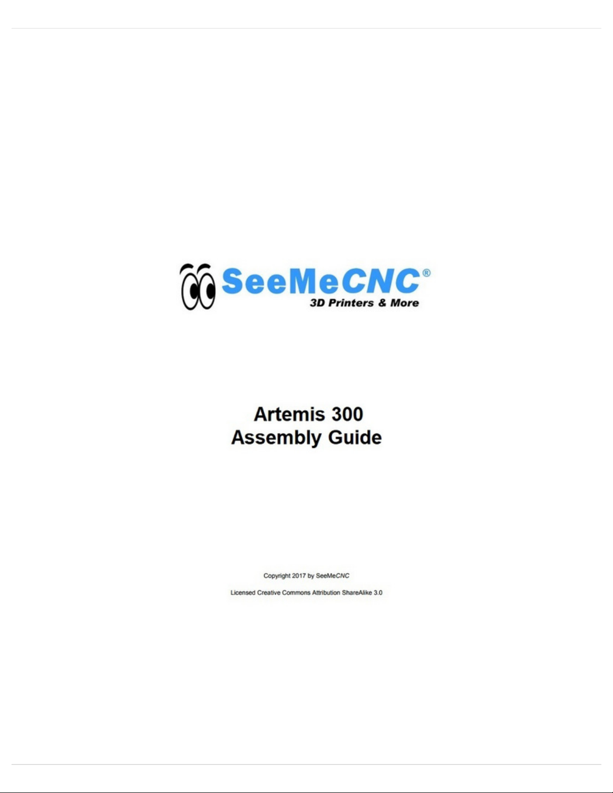
Step 2 — Unpacking
Inside the large box that the Artemis 300 comes in, are the rails, and two medium sized boxes.
Carefully remove the rails and set them aside.
Remove the two medium sized boxes and CAREFULLY cut the packing tape.
The pictures in this step show the base assembly. There is yet another box within this box. This
smaller box has all the accessories and parts for assembly.
You can carefully remove the shrink wrap from the base assembly. NOTE: There is a small
package of press in rivets shrink wrapped to the base assembly. DO NOT LOSE THESE!
Assembling Artemis 300
© 2018 seemecnc.dozuki.com/ Page 4 of 40
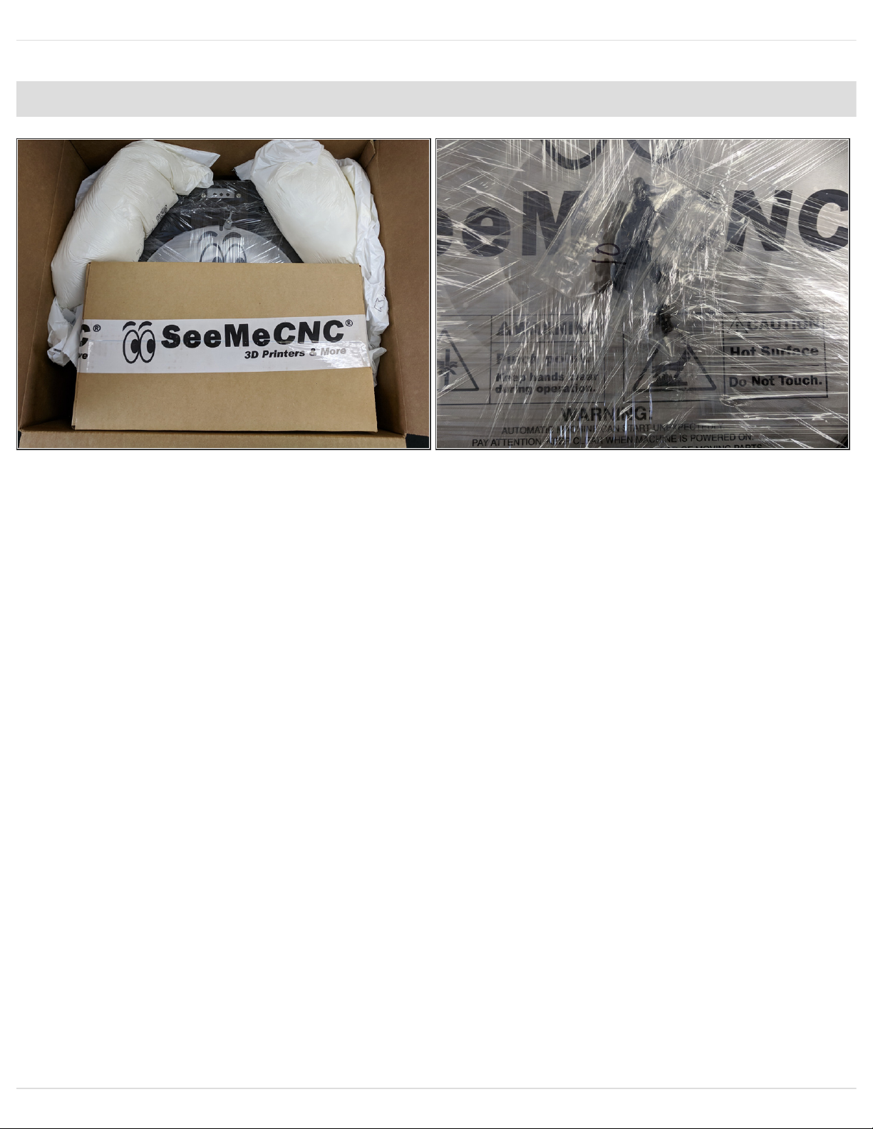
Step 3 — Accessory / Assembly Contents
The smaller box in the base
assembly pack is the accessory /
assembly contents.
Step 4 — Unpacking
The other medium box is the upper assembly.
You can carefully remove the shrink wrap from the upper assembly. NOTE: There is a small
package of press in rivets shrink wrapped to the top assembly. DO NOT LOSE THESE!
One final item in this box is the DUET box. This box contains connectors and crimps. Do not
discard this box!
Assembling Artemis 300
© 2018 seemecnc.dozuki.com/ Page 5 of 40
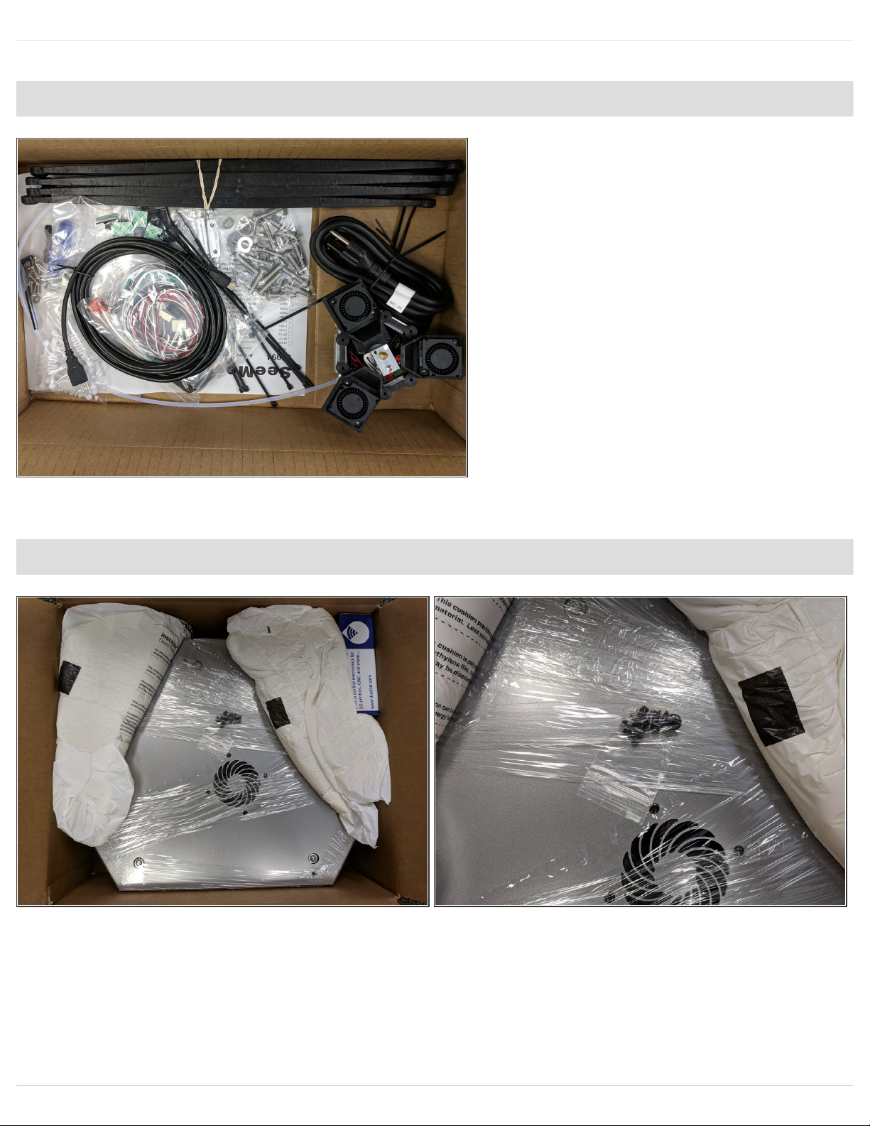
Step 5 — Artemis Contents Unpacked
These are the parts that make up the Artemis 300.
Step 6 — Z Tower
There are 3 towers for the Artemis. 1
of the towers has the extruder and
hot end whip pre-installed. For this
step you can choose either of the
remaining 2 towers to be the Z
tower.
Locate the Z Tower Wire pack.
Remove the wires from the pack and
straighten them out. Be careful not
to lose any of the connectors from
the pack.
The connectors shown will be in the
top of the machine (the side with the
stepper motors).
Please make sure you have the
wires in the orientation shown.
Assembling Artemis 300
© 2018 seemecnc.dozuki.com/ Page 6 of 40
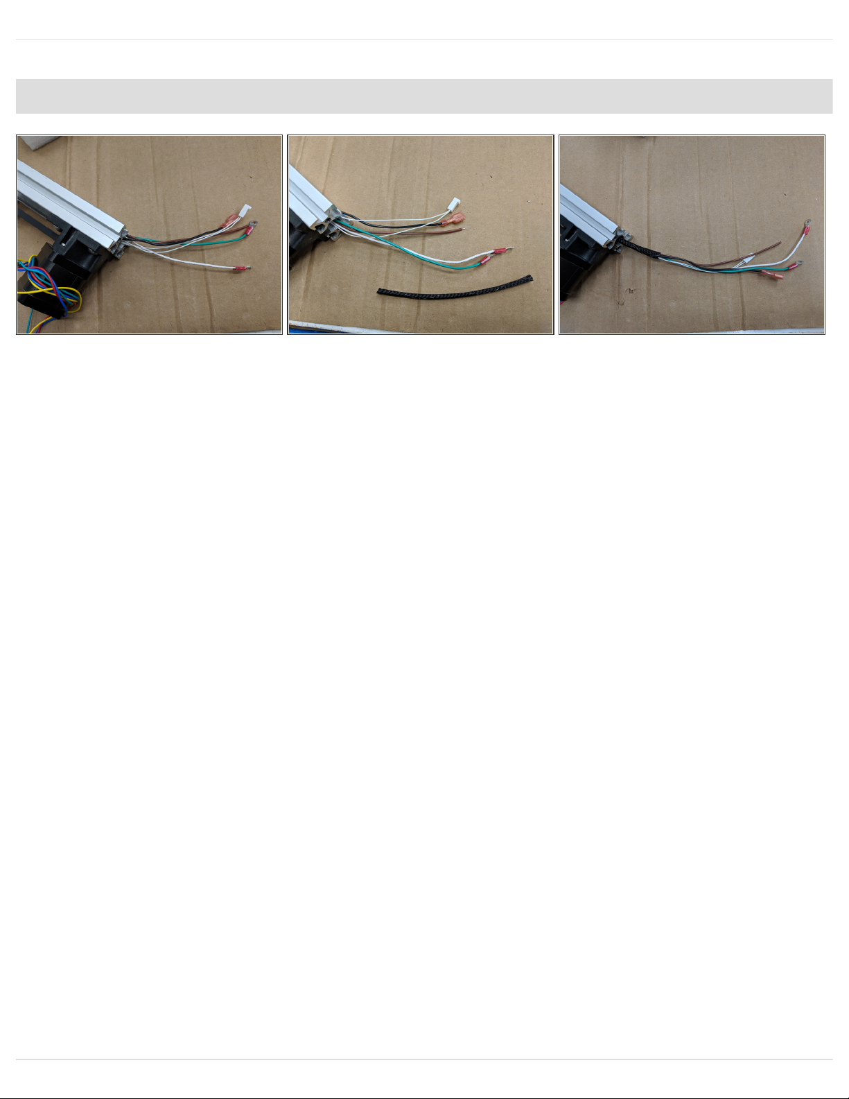
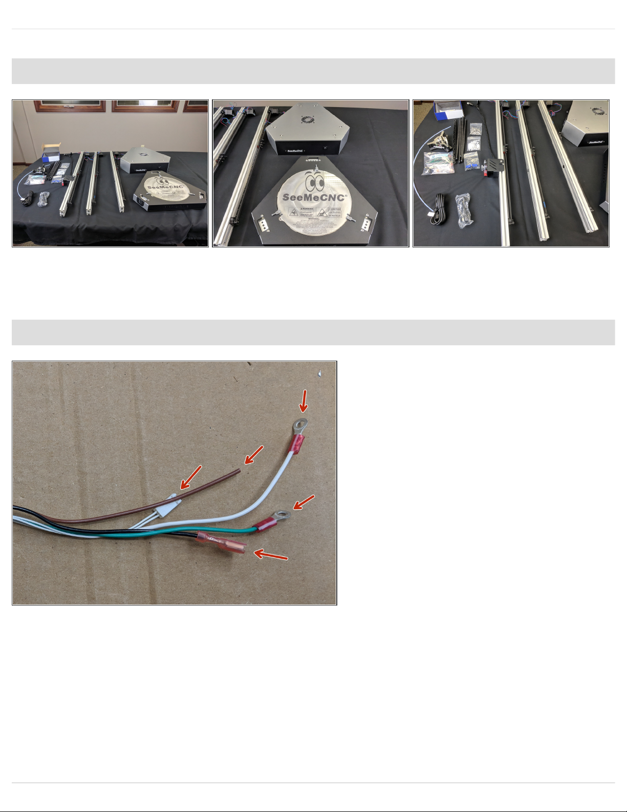
Step 7 — Feeding the Wires in the Z Tower
The first set of wires to feed in the Z Tower are the 18awg wires. These are the thicker wires from
the Z Tower Wire Pack. Please ensure to have them oriented the correct way.
You will feed from the bottom of the tower (opposite the stepper motor). Feed the following:
18awg white and green wire with ring terminal, 18awg black wire with straight spade terminal,
18awg wire with NO terminal.
These wires can be fed by pushing small bits at a time. If you feel resistance, back the wires out
about 25mm and then try pushing forward again.
Ensure you get the same number of wires exiting the end the end of the tower that you started
feeding.
Now run the remaining wires. This is easiest using a piece of filament to pull wire.
Run the included mesh loom over the wires and secure with a zip tie. This is to secure the wires for
later steps.
Assembling Artemis 300
© 2018 seemecnc.dozuki.com/ Page 7 of 40
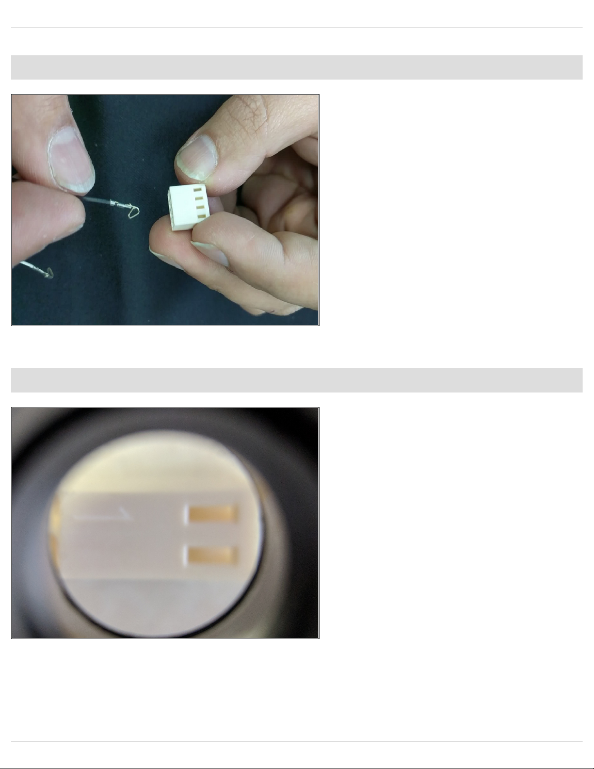
Step 8 — KK Connectors
THIS IS AN INFORMATIONAL
STEP FOR FUTURE
PROCEDURES. NO ACTION IS
NEEDED FOR THIS STEP.
Please watch the video.
Make sure that the contact locks into
the connector shell. The contact has
a small metal tab. The tab will pop
up into the slot on the face of the
connector shell, locking the contact
in place.
Step 9 — KK Connectors PIN ID
THIS IS AN INFORMATIONAL
STEP FOR FUTURE
PROCEDURES. NO ACTION IS
NEEDED FOR THIS STEP.
The KK connectors have a #1
molded into them for pin
identification. This is very difficult to
see if you are not looking for it.
Assembling Artemis 300
© 2018 seemecnc.dozuki.com/ Page 8 of 40
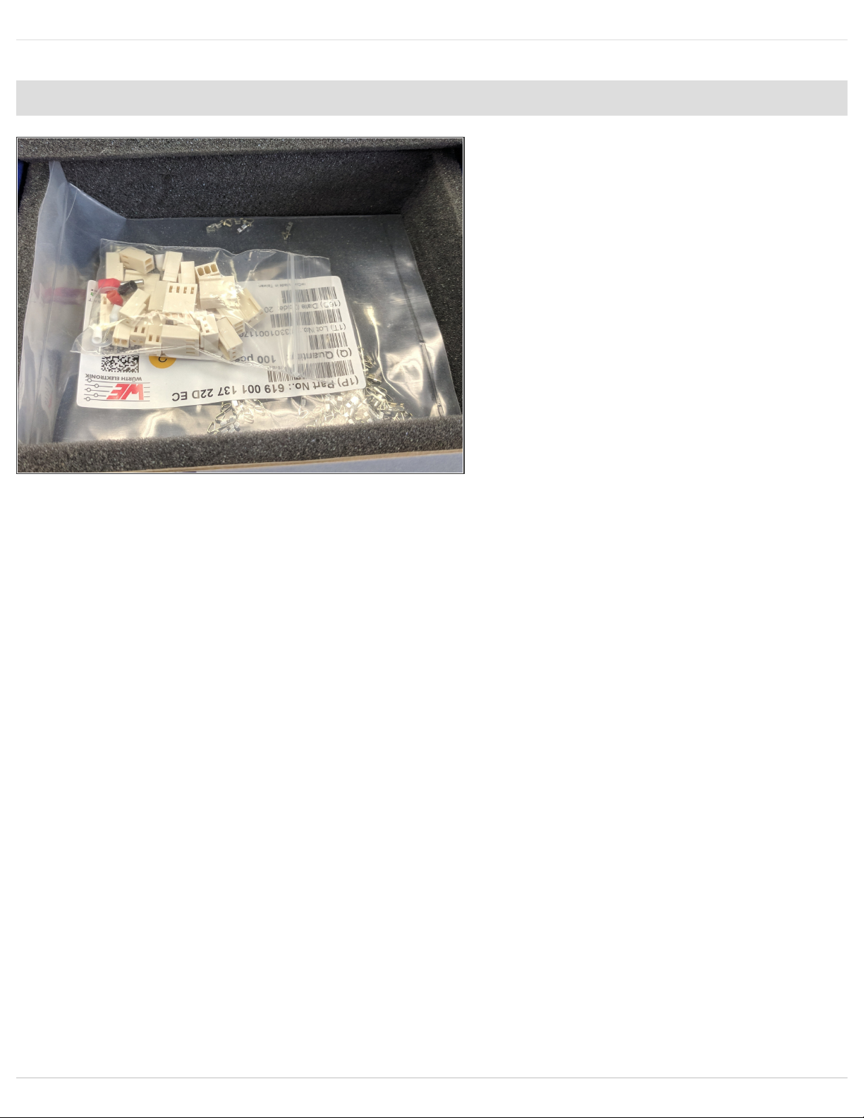
Step 10 — Installing Connectors on Wires
There are two different connectors.
The off-white connectors in the
DUET controller box are slightly
different than the KK Molex (bright
white) connectors SeeMeCNC
installs on the wires. If you need to
replace any terminals using the
DUET supplied connectors, replace
the enter end of the motor or switch.
The crimp terminals are NOT
interchangeable.
IF THESE KK CONNECTORS ARE
NOT WITH THE Z TOWER WIRE
PACK, THEY WILL BE LOCATED
IN THE DUET BOX SUPPLIED
WITH YOUR PRINTER KIT.
Assembling Artemis 300
© 2018 seemecnc.dozuki.com/ Page 9 of 40

Step 11 — Installing Connectors on Stepper Motors
Current machines will have the motor connectors already installed. Newest machines will have
Red, Green, Yellow, and Blue wires instead of what is shown. If this is the case, ignore this step.
Machines AFTER 3/20/2018: Motors can have a black connector and different color wiring, They
are connected with the smooth side of the plug towards the edge of the Duet.
The wires of the motion stepper motors will install into Molex KK 4 pin connectors. These wires will
install into the connectors similarly to how previous wires were installed into the KK connectors.
PIN 1 is indicated with a "1" on the connector. It is difficult to see if you are not looking at
it closely, but it is there.
Blue wire: Pin 1
Red wire: Pin 2
Green wire: Pin 3
Black wire: Pin 4
Assembling Artemis 300
© 2018 seemecnc.dozuki.com/ Page 10 of 40
Table of contents
Other SeeMeCNC 3D Printer manuals

SeeMeCNC
SeeMeCNC orion delta User manual

SeeMeCNC
SeeMeCNC Rostock Max User manual

SeeMeCNC
SeeMeCNC Rostock MAX v2 User manual

SeeMeCNC
SeeMeCNC Rostock MAX v2 User manual

SeeMeCNC
SeeMeCNC ERIS DELTA User manual

SeeMeCNC
SeeMeCNC Artemis User manual

SeeMeCNC
SeeMeCNC Delta User manual

SeeMeCNC
SeeMeCNC Rostock Max v3 User manual

SeeMeCNC
SeeMeCNC Rostock Max v3 User manual

SeeMeCNC
SeeMeCNC Rostock MAX v2 User manual


